I try and publish as much as I can about the work I do – it gets the science out there so it can be built on by others which is hugely important for pushing research forward. Sometimes I may not have enough experience or data in a specific field myself to be able to pull together an entire publication, however I do get asked to help with work in a wide range of research fields especially with regards to imaging.
One area which has strong links with skin and imaging is that of forensics, and UV photography has applications in that field. Due to my work on the measurement of lens transmission in the UV, Dr Kevin Farrugia, at De Montfort University, approached me in 2020 with some questions about UV imaging, which led to some interesting and thought provoking discussions about what was actually important when doing UV imaging.
Always nice to get a mention in the acknowledgements on a paper (you’d be shocked to find out how often this doesn’t happen after these types of discussions), so thanks Kevin. Part of having expertise in an area is the responsibility to teach others and pass on that knowledge, especially to Universities, and it is something I will continue to do in the future.
Some purchasing experiences can be a bit of nightmare. Unfriendly or unhelpful staff, packages that go ‘missing’ during shipment, and courier companies that feel as though leaving your parcel on someone else’s doorstep and providing you with some tantalizing clues as to where it is, is as much fun as going on an organized treasure hunt.
Other companies though, just get it right. Enter Thorlabs. Thorlabs produce and sell a huge range of optical components, and I often use their parts and adapters when building lenses such as a UV lens I made based on their 79mm UV Aspheric lens.
Lens build based on the Thorlabs 79mm UV Aspheric lensThorlabs 79mm UV aspheric lens in place
This has proved to be used for UV imaging and can potentially even be useful well down into the short wavelength UVC region.
UV image of a Dandelion taken using the Thorlabs UV aspheric lens
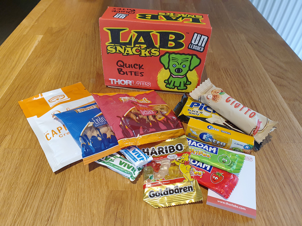
But this where they get a big ‘tick’ from me – customer service. When you ring them up and ask for advice, they genuinely sound as though they want to help. Thank you, thank you, thank you. Add that to the range of kit they sell and the good prices and you have a winning combination. And then we come to the icing on the cake. In with the deliveries you often get Lab Snacks – nibbles and treats to help make the day go more smoothly (by the way Thorlabs, my wife says thank you so much for these).
Thorlabs Lab Snacks with the delivery
In a world of mediocre customer service, it is great when you get something like this. Thank you Thorlabs, I’m a very satisfied customer and shall continue to buy many more optical components from you in the future.
As part of life’s journey sometimes it is useful to look back to see where you’ve come from, so today, please excuse my self indulgence as that is just what I’m going to do with regards to my experiences with ultraviolet (UV) photography. I’ll put a few links to pieces I’ve written along the way, to provide more background where needed. I’ll also mention a few of the UV equipment related suppliers and contacts I’ve made along the way, although I’d like to make it clear that I am in no way sponsored or funded by them.
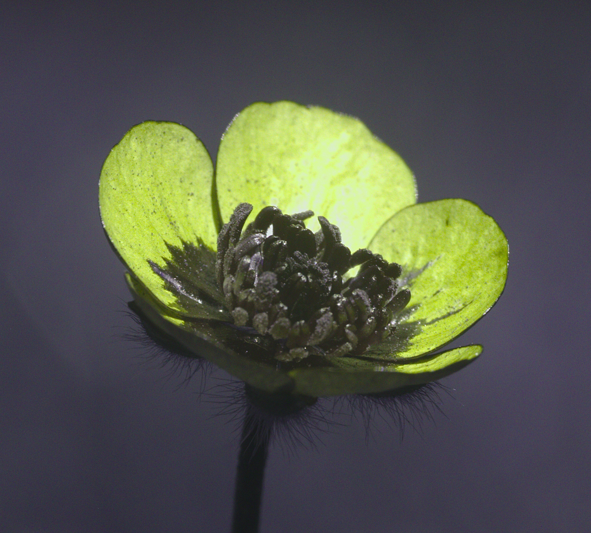
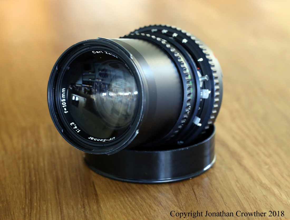
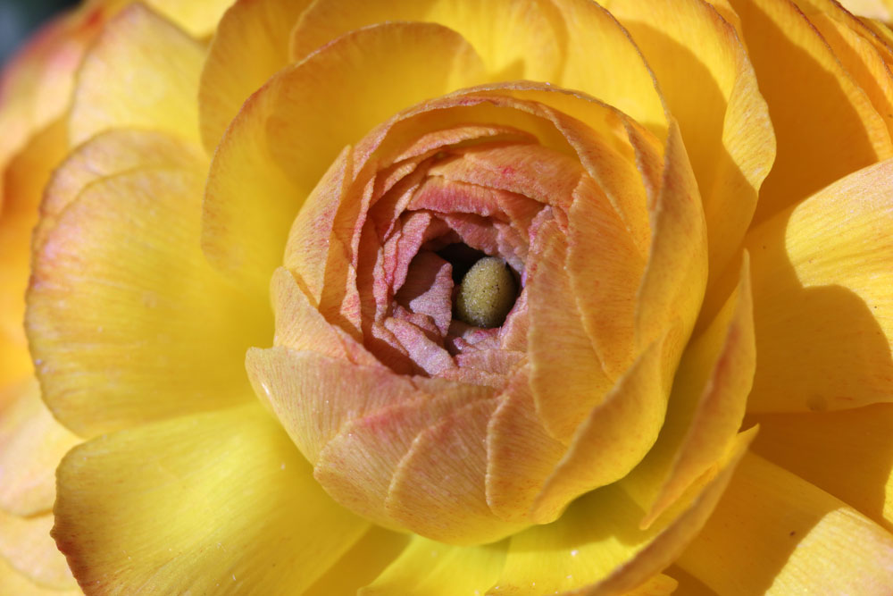
UV photo of a Buttercup taken using a Zeiss UV Sonnar 105mm lens and UV modified Canon EOS 7D camera (modified by Advanced Camera Services Ltd, UK)
Photography has been a part of my life for a long time – even when a boy I would often have a camera in my hand, and I suppose I have one of my brothers to thank for that. He was a film cameraman so was (and still is) a great inspiration to me. My other brother (also an inspiration) while not a photographer was an artist so pictures and picture taking was always around while I was growing up. In 2000 I bought my first proper film camera under supervision of a good friend from University and of course being a scientist looked for things to do with it beyond taking ‘snaps’. This led me to infra-red (IR) photography and the even more mysterious UV photography. UV imaging was one of those mythical areas which used mysterious lenses made of exotic materials such as quartz and calcium fluoride, and needed strange filters which blocked all the visible light, and it was all very intriguing. I even tried doing some with a normal camera lens and some UV sensitive film, and got some ‘less than optimal’ results. So as a technique I filed it away as one of those ‘to be done later’ approaches.
Fast forward a few years and I was working for P&G in their Skin Care group, and again UV imaging appeared as an area of interest from my mentor. Like me he found it a fascinating area and even had some of these mythical UV lenses from his research. However it was still well beyond my means at the time to go into this in any serious way, and I settled for IR photography as a way of getting my geeky fix for non-visible photography.
We now jump a few years forward again to the winter of 2017 and someone I was working with asked me if I could come up with a way of visualising sunscreens and how they spread to help with development of new topical sun protection products. Given how sunscreens absorb UV light, it immediately got me wondering whether UV photography could be used for this. But there was a problem – when you hit a film of sunscreen with a bright light, you get a lot of reflection from its surface which hides information on the film morphology. Easy I thought, let’s just cross polarize the light source and camera like I do for visual light photography. Oh, the naivety of youth. As with many things UV related this proved to be a little less straightforward than I originally thought, but it started me down the route of seriously looking at UV photography. This was where I jumped down the rabbit hole…..
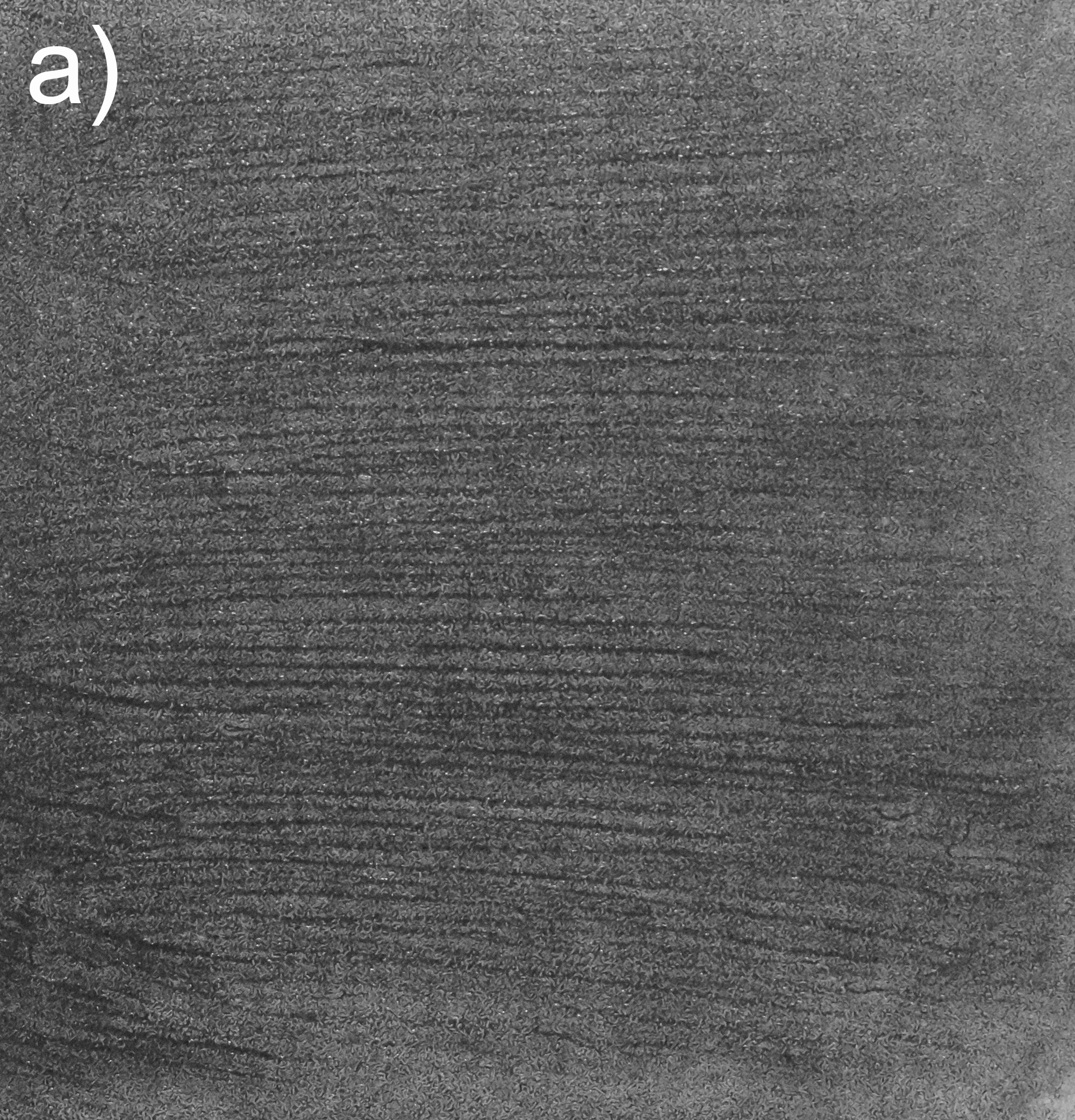
After working with a UK supplier (Advanced Camera Services Ltd) to get a UV converted camera, a lens and UV flash, I then designed a cross polarisation setup for it, the result of which was a system which could do cross polarised images of sunscreen films showing the film morphology. This was written up and published in the International Journal of Cosmetic Science, as being able to combine UV absorption of the film with information about the film morphology looked to be giving a more accurate correlation with in-vivo measured SPF values that did not considering the morphology.
Cross polarised image of a) a poorly spreading sunscreen product, and b) a sunscreen product which spread well. The poorly spreading product shows streaks corresponding to variations in the final film thickness
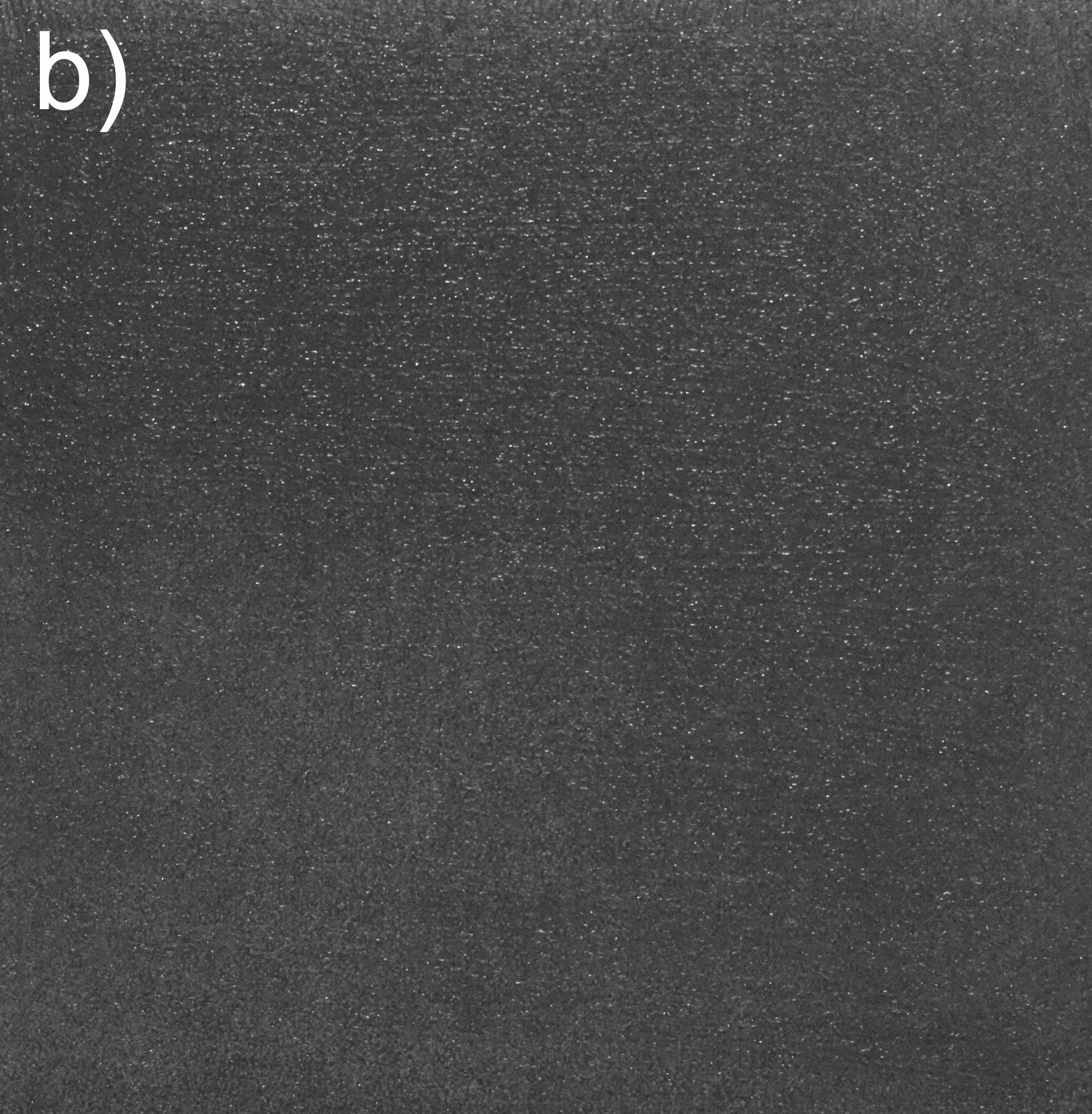
It was about this time that I also came across the Ultraviolet Photography forum. This collection of individuals from around the world had a tremendous background knowledge of all things UV photography related, and time spent on the forum was time well spent. I also found Dr Klaus Schmitt who is a UV imaging expert and dealer in unusual lenses. This led me to my first personal UV purchase – an Asahi Ultra Achromatic Takumar 85mm f4.5.
I suppose I’ve become a bit of a collector, but I see it more as the role of a curator. Being made in small numbers most of these are of historical interest, so I look after them and will eventually pass them on to the next generation of photographers. All of these lenses have good (and some bad qualities) when it comes to use in UV but some of them have enough reach to get down well into the UV region below 300nm. The plan is to eventually write up research done on or with all of these lenses at some point. Somehow I get the feeling this will end up being a retirement project…. I also make my own lenses from the range of parts that Thorlabs sells (big boys Lego).
Of course lenses are only part of the story and you need a camera to capture the image. For my initial sunscreen work I bought a UV converted camera from Advanced Camera Services Ltd in the UK, which I still use for day to day UV imaging. Having a built in UV filter over the sensor is great for an SLR camera as you can still use the eyepiece (although focus point will likely be different in the UV depending on the lens). One of the big issues with modern camera sensors with regards to UV imaging is the presence of the Bayer filter – the transparent coloured layer which creates the red, green and blue image on most sensors. While this is great for the visible region, the dyes used absorb loads of UV, especially at the shorter wavelengths, so has a big impact on camera sensitivity. Fairly early on I came across a company in the US – MaxMax (Llewellyn Data Processing LLC) – who were offering monochrome conversions of cameras, where they were removing this Bayer filter layer in a very controlled way, so I got one of my cameras converted. In fact I was so impressed with his work, that I’ve ended up getting various cameras worked on by him, including two Canon EOS 5DS R’s (one to monochrome and one just for multispectral imaging with the Bayer filter still intact). It was these Canon cameras which were the basis for my publication in the Royal Photographic Society Imaging Science Journal in which I used a device I’d built for measuring camera sensor sensitivity to look at how thee conversions impacted UV imaging ability. I actually have another paper looking in more depth at monochrome camera conversions and spectral sensitivity in the UV, visible and IR which will hopefully be published later this year.
Next we come to filters. Blimey, filters for UV imaging. This can be a bit of tricky area as of course a filter for UV imaging needs to be able to effectively block anything which isn’t UV. For a typical camera sensor this mean blocking from 400nm up to around 1200nm and because camera sensors tend to be more sensitive to visible and IR than to UV, the blocking of these wavelengths needs to be good. Very good. A lot of people use the Baader U filter from Baader Planetarium for their work. This is a filter designed for telescopes, so typically needs a bit of modification for using on a camera lens, and is dichroic which can lead to some odd colour fringing on wide angle lenses. I’ve also found the filters made by UVIRoptics to be very good, and he offers non-dichroic ones which don’t have the colour fringing issue with wide angle lenses. Also Invisible Vision here in the UK offer a good 308nm UVB filter with a mount suitable for normal camera lenses. I must admit, I’m a bit of a filter junkie and have far too many of them, but the set of 10nm band pass filters which go from 310nm to 390nm from Edmund Optics and Thorlabs have been very very useful, although they are only 1″ diameter, they are fine with the 105mm UV Rayfact macro lens (and other small element lenses).
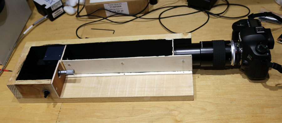
Actually, while working in the UV I’ve found that a lot of stuff needs to be built as it cannot be bought (or if it can be bought, you need very, very deep pockets). This has led me to building my own setups for measuring camera sensor sensitivity and lens transmission, both of which have led to publications in peer reviewed journals. The paper containing the lens transmission work was awarded the Paper of the Year for 2020 in the International Journal of Cosmetic Science which was a great honour to receive.
Building my camera sensor sensitivity measurement setupIJCS 2020 Publication prize winner announcement for my paper “UV reflectance photography of the skin: what are you imaging?”.
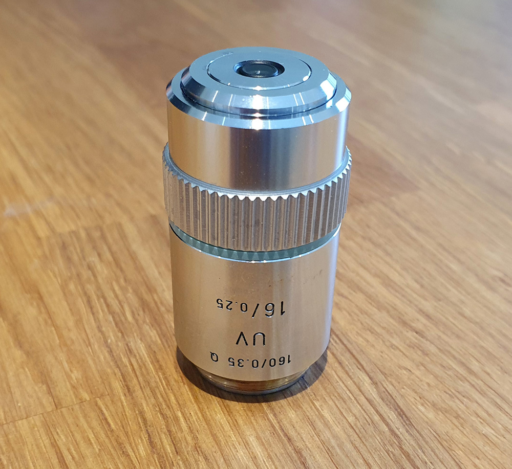
The last year has of course been hugely difficult for many people. When the first lock down came around I found myself in need of a new project to keep busy. As I had relatively little experience with microscopy, and given its very visual nature, I thought it would be a good skill to learn to compliment my other imaging work. I decided to buy an older microscope in need of fixing up, so settled on an Olympus BHB from the 1980’s. This poor thing looked like it has been stored in a field for a while, but could be taken apart and cleaned with relatively simple tools. Like many projects it became somewhat obsessional for me, and I soon got to wondering whether it could be transformed into a UV transmission microscope. This would be no simple task as there is a lot of glass in a microscope. So I set about learning about UV microscopy and kept an eye out for second hand equipment such as objectives and condensers. I had a couple of lucky purchases relatively early on and managed to find a Leitz 16x UV objective with good UV transmission down to and below 300nm, and an vintage Zeiss quartz condenser (although I did also make my own condenser at one point using a UV fused silica half ball lens).
I also came across the Quekett Microscopical Club which was founded in 1865 and even has its own peer reviewed journal. What better place to learn about old microscopy equipment I thought and applied to join. As with the photography I’ve found myself no collecting anything related to UV that I can find and use so have a wide range of UV lenses, both refractive (such as the Zeiss Ultrafluars), and reflecting (mirror lenses). All of these have been bought second hand as new they would have had eye-wateringly high prices.
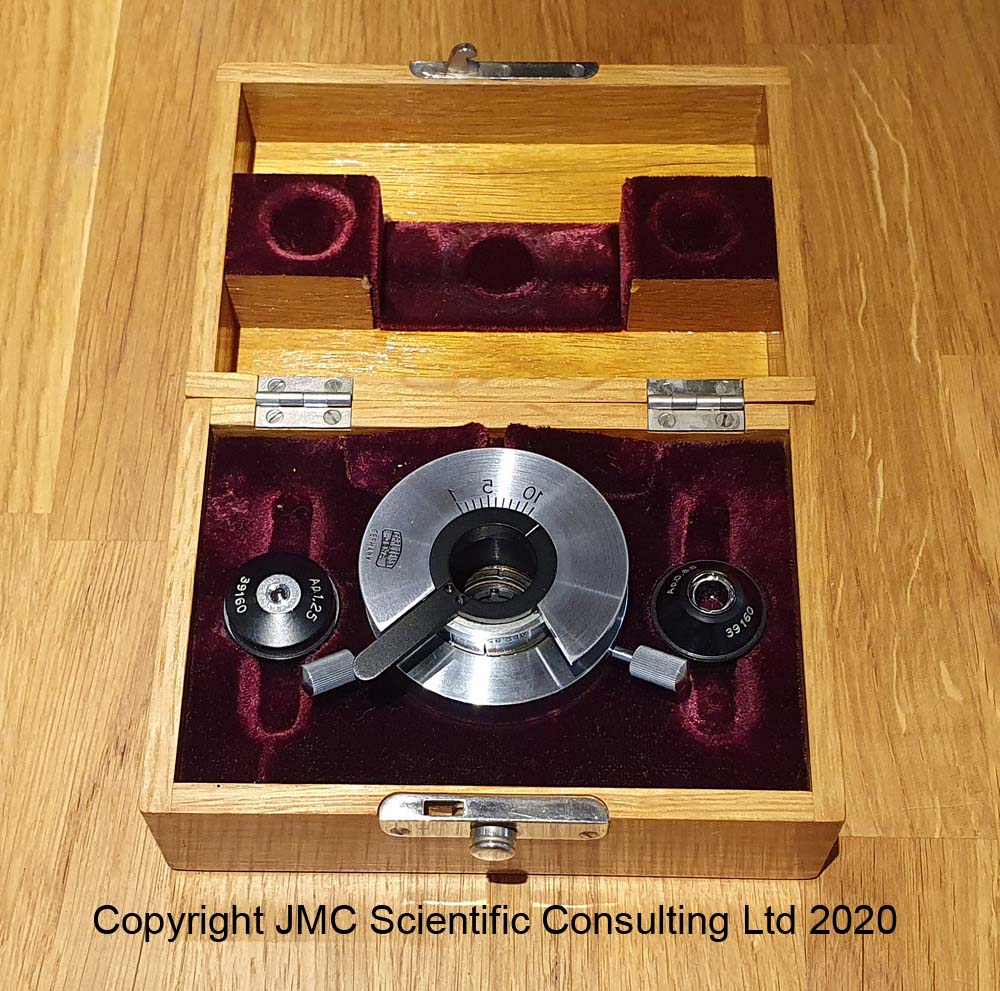
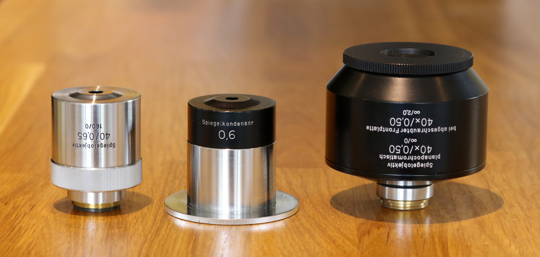
Zeiss reflecting microscope objectives and condenser
The UV microscope is now complete, although as a tinkerer it will be improved upon, and I am starting to do research into sunscreens using it.
Scientifically, my UV journey has been challenging, fascinating, frustrating at times, but ultimately very rewarding and is an area I shall be continuing to work with in the future. In addition to the obvious areas of interest such as sunscreens and skin imaging, my plan is to explore different areas such as forensics, geology and even anthropology to see what looking at things in a different way can bring to research in those fields. Microscopy has proved to be a fascinating research area for me and I’ve already written a couple of UV related articles on it with more to come in the future.
Thank you for reading and if you’d like to know more about my work you can reach me here. I’ve included a small publication list at the end of the article which includes some of the key articles I’ve written on this area along with the talks I’ve given to date.
UV related publications and talks
“Yooperlite – Imaging the fire within using UV”, JM Crowther, Quekett Bulletin, 2021, 80, 53-56.
“Chapter 28 – Dermatological imaging – A survey of techniques“, A Davies, JM Crowther, in Photography in Clinical Medicine, Ed. P Pasquali, 2020. ISBN 978-3-030-24543-6. https://doi.org/10.1007/978-3-030-24544-3_28
“Chapter 29 – Beyond the visible: UV, IR and fluorescence imaging of the skin“, JM Crowther, A Davies, in Photography in Clinical Medicine, Ed. P Pasquali, 2020. ISBN 978-3-030-24543-6. https://doi.org/10.1007/978-3-030-24544-3_29
“UV reflectance photography – what are you imaging?“, JM Crowther, International Journal of Cosmetic Science, 2020, 42(2), 136-145. https://doi.org/10.1111/ics.12591
“Visualising Sunscreens Using UV Photography”, presented at the Sun Protection Conference, London, UK, 2019.
“Imaging of the skin – UV, visible, IR”, presented at the Royal Photographic Society Imaging Science Group meeting, London, 2019.
“The big reveal: UV imaging uncovers sun protection, skin dryness and microbiome“, JM Crowther, Cosmetics and Toiletries, Sept 2019, p.32-45.
“Understanding colour reproduction in multispectral imaging: measuring camera sensor response in the ultraviolet, visible and infrared“, JM Crowther, The Imaging Science Journal, 2019, 67(5), 268-276. https://doi.org/10.1080/13682199.2019.1638664
“Calibrating UVA reflectance photographs – standardisation using a low-cost method“, JM Crowther, Journal of Visual Communication in Medicine, 2018, 41(3), 109-117. doi: 10.1080/17453054.2018.1476819.
“UV Photographic Imaging – Sunscreens and Skin“, The Cosmetic Chemist, 2018, 15th October.
“Understanding sunscreen SPF performance using cross polarised UVA reflectance photography”, JM Crowther, International Journal of Cosmetic Science, 2018, 40(2), 127-133.
Have you ever wondered what the inside of a microscope objective lens looks like? Why am I even asking that, of course you have, haven’t we all. All the tiny components, the little lenses. Very cool. Sometimes we get to see schematics of what they look like in cross section in manufacturers brochures or in other publications, but usually that is as close as we get to actually seeing what is going on in there.
I recently saw an objective for sale which had been sectioned from end to end by Spectrographic Ltd in the UK, so put in a bid and was lucky enough to buy it. The objective was an Olympus HI M100 1.30 which was unfortunately broken (no working lenses were sacrificed in the making of this section). Looking from the side it looks ok, a bit beaten up perhaps, but ok;
However turn it around and it looks very different.
Keep in mind that this objective lens is only about 25mm long. By sectioning it the amazing engineering that it takes to make one of these is revealed. The lens elements themselves are remarkable, as can be seen when we zoom in on them.
Going from left to right it looks like there are two singlets, and then two cemented doublets. Keep in mind that these are only a few mm across.
The images were captured using a Hoya Super EL 60mm enlarger lens as a macro lens as discussed here.
I’m very impressed by the quality of the section from Spectrographic Ltd, especially considering it is such a small item. This is something that is handy to have when explaining about microscopy – being able to show someone the inside of an objective is a step up from just looking at a sketch on a screen. Now then, where is that broken Beck reflecting objective I got a while back…..
Thanks for looking and if you’d like to know more about this or my other work you can reach me here. And please remember that the images in my site are copyrighted to JMC Scientific Consulting Ltd. If you’d like to share them, please ask first.
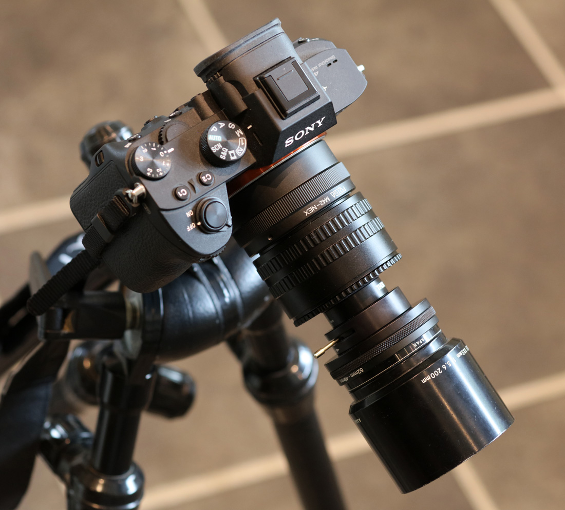
Sometimes in the world of photography we fall into the trap of ‘must buy that expensive lens everyone has been talking about’. However it is possible to use rather humble lenses to take good photos and they can often produce very high quality images for what is a very modest outlay.
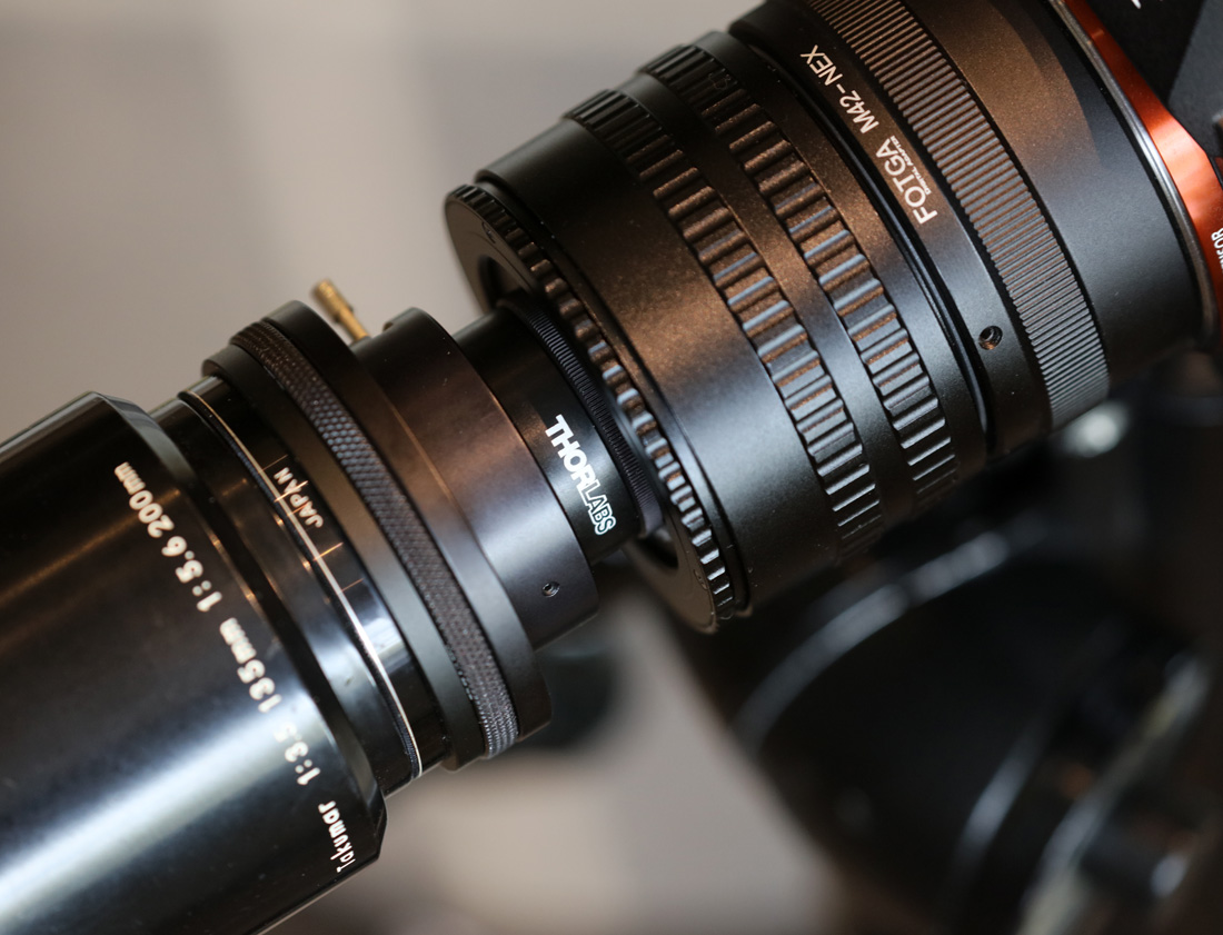
Enter the Hoya Super EL 60mm f4 enlarger lens. This one cost me the princely sum of £30 on ebay. Here’s the lens;
Hoya Super EL 60mm f4 enlarger lens
As mentioned above this was a lens for an enlarger. It has a rather unusual 8 element 4 group lens construction and was designed to cover 6x6cm. The thread is M39 (common for enlargers) and is easy enough to adapt to M42 which is mountable to most cameras with an adapter. I used a helicoid on mine to, to allow me to vary the focus more easily.
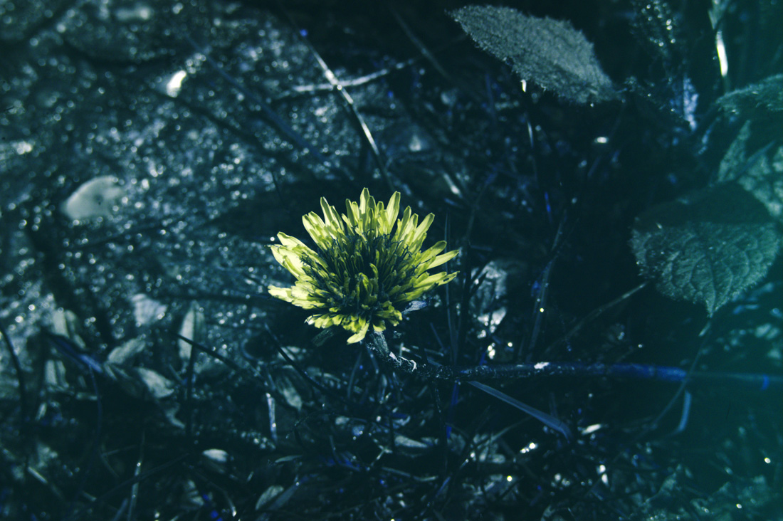
What are the images from it like? Here’s a few from the garden, taken at either f8 or f11 on my Canon Eos 5DS R and hand held. I’ve reduced the resolution for easier sharing here.
Overall I like the images it produces, and the colours are nice. But how about resolution? The image below was pretty much the full frame of the original shot.
And now a crop from the middle of the flower image, kept at the original pixel resolution (i.e. not reduced for sharing).
I think there is plenty of sharpness there.
Enlarger lenses like this tend to make very good macro lenses and can often be had for very little money. Normally they are M39 threaded as well, so once you have the right adapters for your camera it is easy enough to swap between them if you want to try different ones.
We often want the latest and greatest in terms of equipment, but always keep in mind that new equipment isn’t everything. Also, check out the abundant web resources such as the MFlenses forum, and Photomacrography.net for inspiration and get snapping.
Thanks for looking and if you’d like to know more about this or my other work you can reach me here. And please remember that the images in my site are copyrighted to JMC Scientific Consulting Ltd. If you’d like to share them, please ask first.
Measurement of lens transmission in the UV has interested me since I started working with UV photography, and a I’ve ended up building my own system for determining it (see here). However with this setup I was limited to UV and only just getting into the visible, as it could measure from 280nm to 420nm. With recently being in a position to evaluate an Ocean Insight STS-NIR microspectrometer (initial work discussed here) it got me wondering whether I could now measure transmission from 280nm all the way up to 1100nm, as this covers most of the range of camera sensor sensitivity.
To measure lens transmission over such a wide wavelength range meant juggling light source and spectrometer. I ended up using the following combinations;
280nm to 420nm – Hamamatsu LC8 200W xenon light source, Ocean Insight FX spectrometer.
420nm to 650nm – Moritex MHAA-100W halogen light, Ocean Insight FX spectrometer.
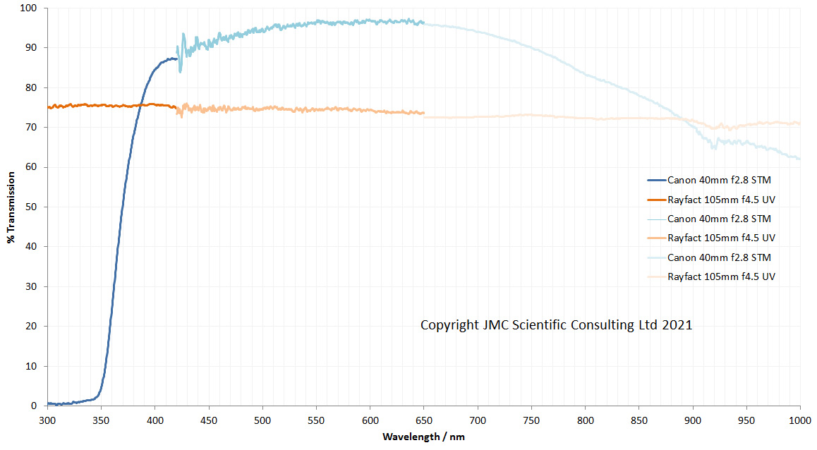
In theory these combinations should have allowed me to see all the way from 280nm to 1100nm. For an initial test I looked at 2 very different camera lenses – Canon 40mm f2.8 STM pancake lens, and a Rayfact 105mm f4.5 UV lens (the modern version of the UV Nikkor 105mm). Here’s how the two lenses looked.
The graph above contains 6 lines – 3 each for the 2 lenses, with each line covering a different spectral range. You’ll notice that the wavelength range only goes to 1000nm, not to 1100nm where the STS-NIR can measure to. This is for a couple of reasons – my Moritex light source light intensity is dropping quickly above 1000nm, and the STS-NIR sensitivity also drops as you get closer to 1100nm. Add these factors together, and then throw in the integrating sphere needed for doing lens transmission measurements and it means that the data gets very noisy above about 1000nm. So I decided that it was only worth plotting it to 1000nm. While I had measurements from 280nm, I started it at 300nm on the graph to make it look prettier – starting at 280nm would make the x-axis scale look odd.
What does this tell us about the 2 lenses? The 2 lenses behave very differently to each other. The Rayfact 105mm f4.5 UV lens has a relatively flat transmission spectrum from 300nm all the way to 1000nm, varying between about 75% at 300nm to about 70% at 1000nm. This is actually pretty close to the data Rayfact share for the lens, which starts at about 78% at 300nm and drops to about 70% at 900nm. The Canon 40mm f2.8 STM pancake lens is very different. It very effectively blocks the light below 350nm, but in the visible region has very good transmission – up above 90% for most of the visible spectrum. Its transmission then drops quickly in the IR as the wavelength increases. This is not surprising, as understandably the Canon lens is optimized for imaging in the visible spectrum. The visible spectrum data is a bit noisier than I expected, especially towards 420nm. Longer acquisition times would help there.
What have I learned here? With the light sources and spectrometers I have I can measure lens transmission from deep in the UV all the way up to the IR. Sensitivity at the top end is lacking a bit which limits me to about 1000nm, although I have a couple of ideas about how to address that in the future. Lens alignment is critical for the measurements here. My setup is horizontal and to get the most accurate results I need to make a stand for each lens to be tested to hold it in exactly the right position for all the measurements. With a vertical setup this would be easier, but at the moment I have no way of safely positioning my lights in a vertical orientation, so horizontal it is for now.
Thanks for reading and if you’d like to know more about this or any other aspect of my work, I can be reached here.
As small business owner working in the research and development area, it is vital for me to keep expanding my capabilities and refining the portfolio of what I can offer to clients. Although I already have a wide range of UV, visible light and IR imaging equipment, along with UV and visible spectroscopy capability (Ocean Insight FX spectrometer), which I use for looking at lens and filter transmission, IR transmission spectroscopy is an area which I am currently lacking. Given the financial upheavals of the last 12 months, the decision to invest in a new piece of kit is not made lightly and new kit must fill a gap in my measurement ability.
My spectroscopy interest is driven mainly by my photography. Camera sensors are mainly sensitive between about 300nm and 1200nm, so this is my area of interest. My Ocean Insight FX spectrometer covers my needs from 250nm to 800nm, and I’ve been very happy with that over the years. Going above 800nm is something I’ve been thinking about for a while, as understanding the behavior of filters for UV photography in the IR is very important – even small leaks in the IR region can be a huge problem for UV imaging. In an ideal world I’d like a spectrometer that would be good for up to and just above 1200nm, however that is a bit of an issue as standard solid state spectrometers tend to only be good up to about 1100nm. Above that you tend to get into more exotic sensors such as InGaAs (indium gallium arsenide) and the costs go up very quickly. As a compromise then, I decided to look at the IR ones with conventional sensors and able to measure up to 1100nm. Between 1100nm and 1200nm the camera sensitivity is dropping rapidly, so this is a compromise I am willing to accept for now.
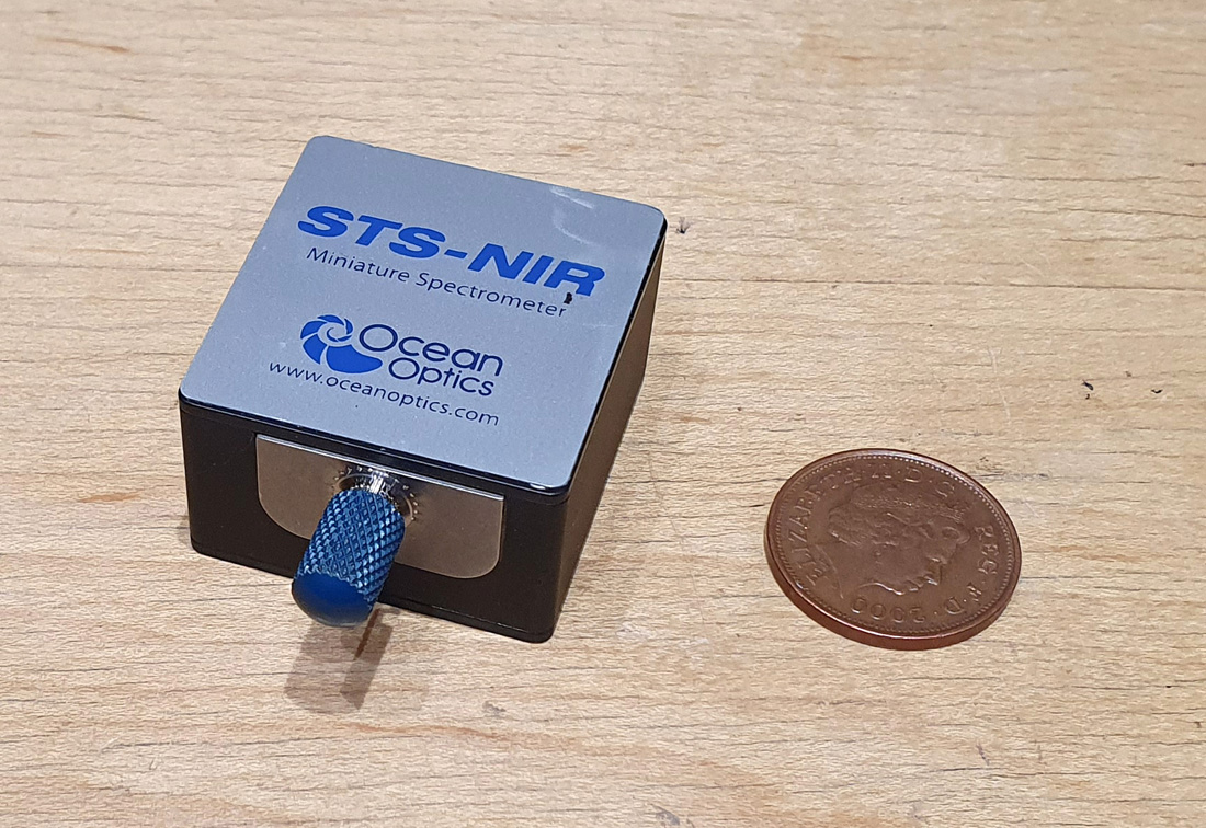
I do a lot of my research from home and my workshop space is limited. As a result of that I tend to look for compact equipment. Combining sensitivity from around 700nm to 1100nm with small size of equipment led me to the Ocean Insight STS-NIR spectrometer and I’ve been fortunate enough to get one of these to evaluate. Initially I was a little skeptical as to whether such a small spectrometer would give good results. And when I say small, I mean small. Here it is in the flesh, next to a 2p coin.
Ocean Insight STS-NIR microspectrometer next to a UK 2p coin
This spectrometer is tiny – 40x42x24mm – with a fiber optic connector at the front, and a USB socket at the rear. Could this really give good data from 650nm to 1100nm?
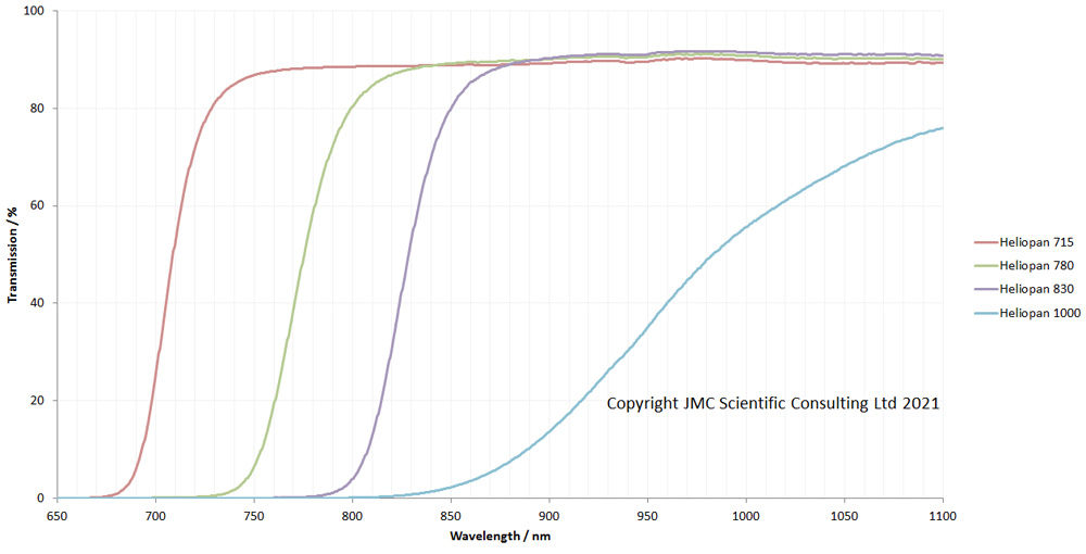
As a first test I decided to look at a range of IR photographic filters – Heliopan 715, 780, 830 and 1000 – which I use for IR imaging. Light source wise I used my Ocean Insight DH-2000-BAL and set everything up for transmission measurement. Here’s how the filters look.
Heliopan 715, 780, 830 and 1000 IR filter transmission
Well, that was pretty impressive for an initial test. The filter transmission curves were as expected and very clean. Up in the 1000 to 1100nm region, the data get a little more noisy, but the sensor is losing a bit of sensitivity up there and the light source is dropping in intensity as well.
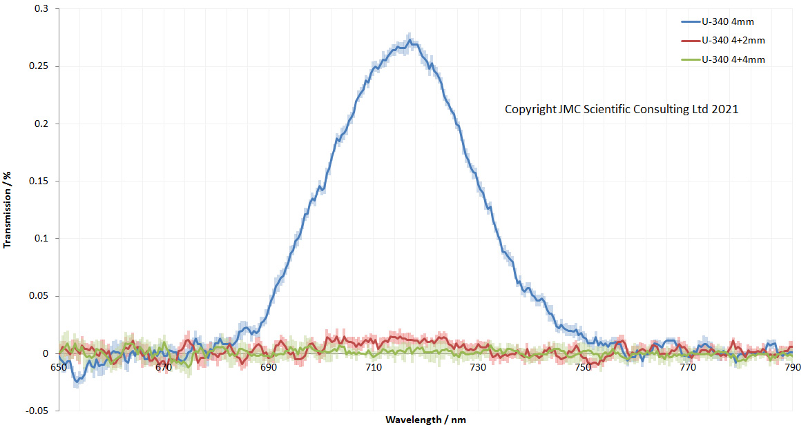
As a next test I took some of my Hoya U-340 filters (from UVIRoptics), and started stacking them up on top of each other. Hoya U-340 is a bandpass filter which has good UV transmission, but does have an IR leak at around 725nm. Using a combination of 2mm and 4mm thick ones I measured the transmission of 4mm, 6mm (4mm+2mm), and 8mm (4mm+4mm) between 650 and 1100nm.
Hoya U-340 transmission at different thicknesses
Each of the lines above was the average of 10 individual runs, and the standard deviations of the scans are shown as paler coloured error bars on either side of the lines. As expected the 4mm Hoya U-340 showed an IR leak of about 0.25% at around 725nm. This leak was nice and clean with the STS-NIR. Above about 1020nm the data for all three filters gets a bit noisy – as mentioned above the sensitivity of the sensor is low up there at the extreme top end, and the light source intensity drops too, so I’m not surprised to see that.
How about if we zoom in to the the 725nm and look in a bit more detail?
Hoya U-340 filters of different thicknesses – transmission in the 725nm region
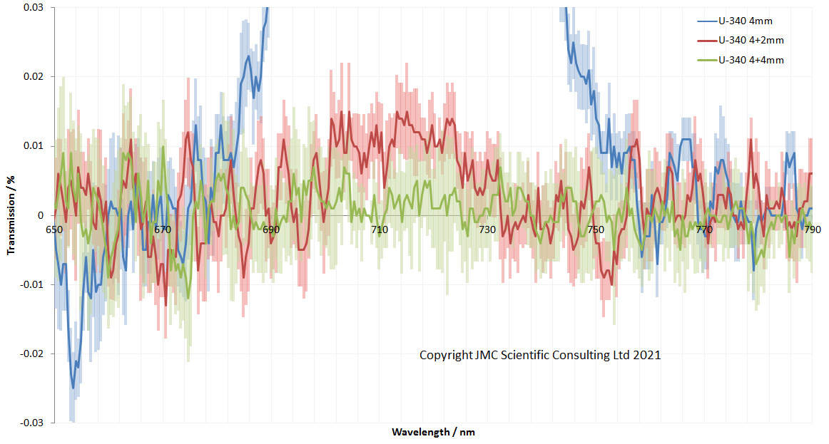
The standard deviation error bars can be seen more cleanly like this and it shows very good reproducibility. The leak in the 6mm stack looks to still be visible and different to the 8mm stack. This can be seen more clearly by zooming in yet again.
Hoya U-340 filters of different thicknesses – transmission in the 725nm region, zoomed in
At this scale, the leak in the 6mm stack at 725nm can still be seen, as about 0.01% (this equates to Optical Density OD4 blocking of the IR). By the time you get to 8mm thick, the leak can no longer be seen due to the extra thickness of the filter stack. So, again, very impressive result from the little STS-NIR microspectrometer.
What have a learned so far? I’ve been very surprised and impressed by the Ocean Insight STS-NIR. For such a small spectrometer it gives very good results. It’s proved that it is capable for assessing filters, and I hope to try it for looking at lens transmission too, although this will be a bigger challenge for it (and my light sources). In theory with the lights I have I should be able to measure lens transmission between 280nm and 1100nm using the FX and STS-NIR spectrometers, which will cover most of the area that normal camera sensors are sensitive too.
Thanks for reading and I hope you enjoyed my latest foray in the measurement world. If you’d like to know more about this or any other aspect of my work, you can reach me here.
The award has been sponsored by the Society of Cosmetic Scientists and the paper was aimed at demystifying the aspects of the UV imaging process to enable researchers to understand what it is they are actually seeing. It brings together various aspects of my research, and many of the methods I’ve developed and built myself to characterise cameras and lenses in the UV region.
I’ve always been a firm believer in the peer review process for the critiquing and publication of research, and will continue to actively publish my work in this area in the future.
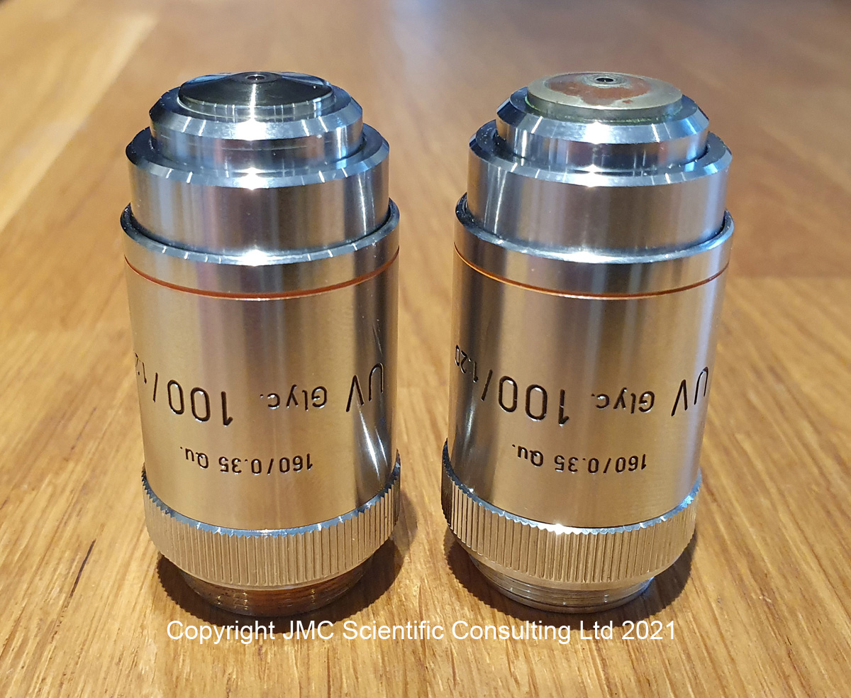
Building my UV microscope has meant a steep learning curve when it comes to the useful items manufacturers have produced in the past. A really steep learning curve. The biggest issue was that the items of interest, such as objective lenses which were made with quartz or calcium fluoride elements, were often made in extremely small quantities. As such there is very little information on them, and tracking down source documents is either very difficult, or in some cases impossible. This brings me to the subject of todays post – the Leitz UV 100x NA1.20 objective. This is a high magnification objective which I was fortunate enough to obtain a copy of a few months ago, and have written about here. I keep an eye out for these and a few weeks ago found another one for sale for a reasonable amount of money, and decided to buy it as a back up copy. When it arrived, I noticed that while it looked similar to the one I already had, it was not identical. So let’s take a look at them and see what is going on with them. Here are the two objectives, my original one on the left, and the new one on the right.
Two Leitz UV 100x objectives. Front view.
From the front, these two objective look the same as the labels are identical. The difference becomes obvious when they are turned around though.
Two Leitz UV 100x objectives. Rear view.
The one I got originally had “Leitz Wetzlar” and “Germany” written on the back, and that was also present on the new one. However the new one also has a 9 digit code number engraved in red on it. It also had a number “2” scratched into it. The engraving looks to be professionally done. Trying to track down the significance to this engraved number has been difficult. I’m not even 100% sure on what it is yet, but it seems to be an identification number from Leitz for a pre-production or prototype version of the objective. Interestingly I have another objective lens (a 50x phase contrast NA1.00) with a similar type of code on it, here, and I’ll come back to this one later.
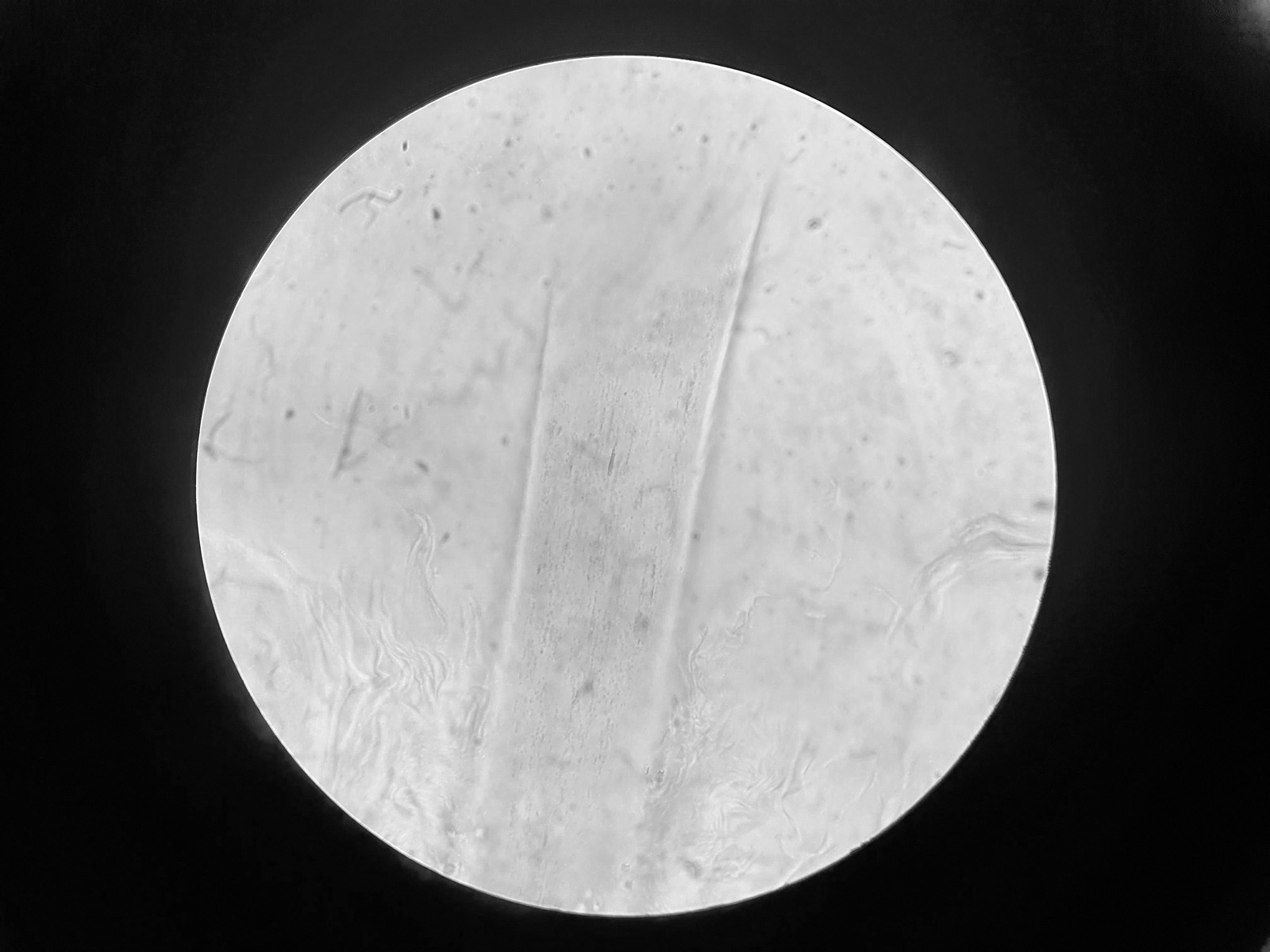
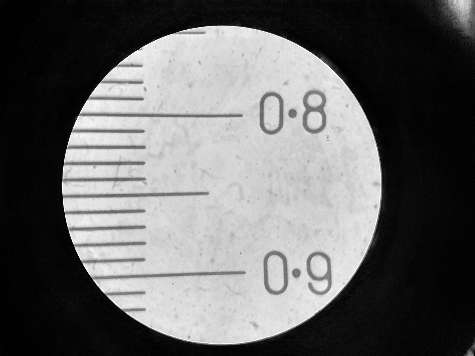
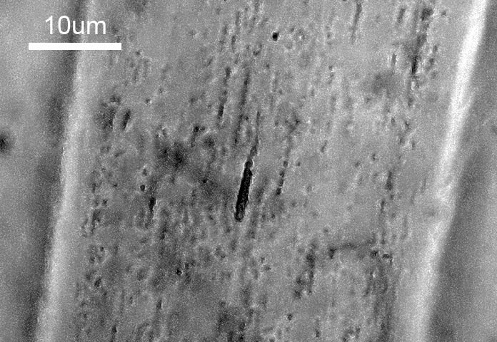
How to the two compare? Some quick brightfield images of a hair on a slide of human skin, and a measuring graticule are given below (taken as a single shot through the eyepiece using a phone). Firstly, for the new one.
Hair on a human skin slide. New 100x Leitz UV lens with red writing.Graticule. New 100x Leitz UV lens with red writing.
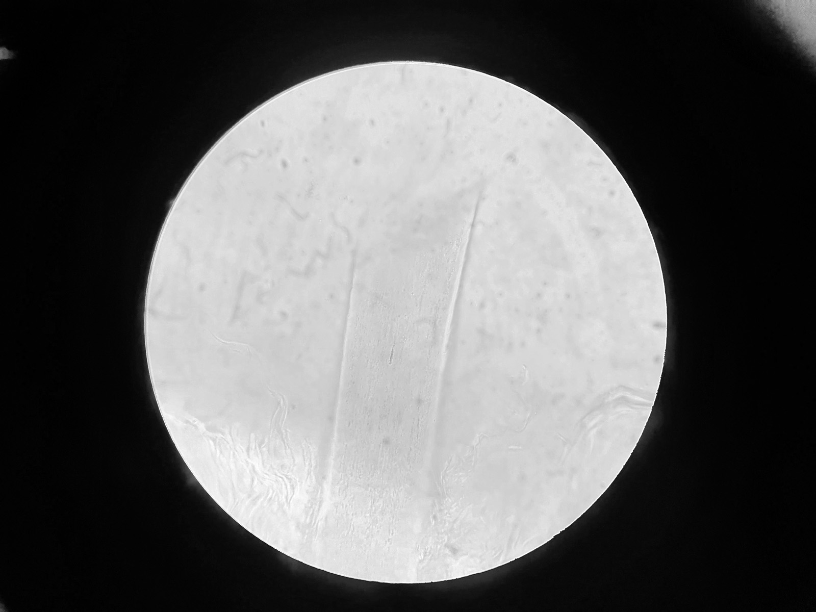
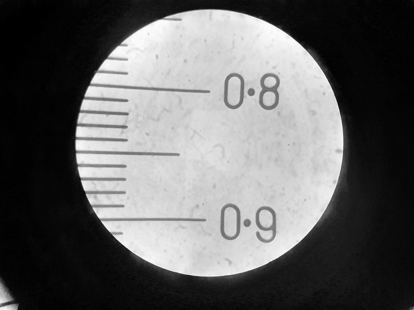
And then the other version of the lens (without the red writing on it).
Hair on a human skin slide. 100x Leitz UV lens.Graticule. 100x Leitz UV lens.
Keeping in mind that these were taken through the eyepiece with my mobile phone, there doesn’t look to be much of a difference between the two objectives. In the middle of the images of the cortex of the hair shaft, there is line of melanin granules. Cropping the original images and boosting the contrast a bit gives the following, again first for the new lens with the red writing.
Melanin in the hair cortex. New 100x Leitz UV lens with red writing.
And now for the other one without the red writing.
Melanin in the hair cortex. 100x Leitz UV lens.
On the face of it, the two objectives look to be behaving similarly. The main reason for my interest in these is because they were designed for use with UV and to be transparent down to and below 300nm. If I compare the transmission through the two lenses, this is where something odd happens.
Transmission through the two 100x Leitz UV objectives.
The original one I had transmitted down to and below 300nm as expected (note these are not absolute transmission values as the lens diameter is small and cuts off some of the beam, reducing the totoal transmission). However the one with the red writing behaves very differently to the original one. Below 400nm the transmission starts to drop until around 320nm. The slight rise again at 300nm for the one with the red numbers is likely an artifact of the measurement and not a real effect.
This is very odd and it doesn’t look as though the one with the red writing has the same transmission in the UV as the other one. Could it be that there are glass lens elements in it, instead of the UV transparent materials which it is supposed to have? Without taking them apart (which I will not be doing) it’s going to be a tough one to answer definitively.
This bring me back to something I mentioned earlier in the post. I have another Leitz lens with red writing on it – the Leitz 50x Pv lens – which I originally discussed here. When I originally tested that lens and measured the transmission I was surprised to find that it blocked the short wavelength UV even though it had ‘Quartzgl’ on the objective barrel, which I assumed meant it was made of quartz. I could not understand why this would be at the time. Could it be that these lenses with the red writing do not have the same optical elements as the final production versions? Perhaps if these are prototypes, they were mainly aimed at prototyping the overall construction rather than the specific optics which were to be used in the final production model, although the 100x ones certainly performs similarly in the visible region. That is purely speculation on my behalf, and unless I can track down an original Leitz employee who worked on them, I’ll probably never find out for certain. Although if I could find another one of the 50x Pv objectives, that would be good to test. So, anyone out there with one, feel free to get in touch.
Where does this leave us? Older equipment can be amazing for those of us involved in research and development, enabling us to buy things which would have been extremely expensive when new, for a fraction of their original price. However we should always remember that rare items such as the ones used for UV imaging were often only made in small numbers, and their suitability for the intended application needs to be verified before they can be used. Test, test and test again. If you’ve made it this far, thanks for reading, and if you’d like to know more about this or any other aspect of my work, you can reach me here.
A few weeks ago I posted some initial work which used a converted high street camera to be ale to make images at 254nm, which is down into the UVC region (see here). Frankly I was stunned to see the camera capture anything at such a short wavelength. The camera used for this was a monochrome converted Nikon d850 from MaxMax, which had had the Bayer filter and microlenses removed. Of the cameras I have, I thought this would give the best shot at seeing that far down, and indeed it did. Some of the folks on the Ultraviolet Photography forum have been looking at image UVC for a while, but until recently I had discounted it as I thought my cameras lacked the required sensitivity to be able to capture anything. After seeing an image with the monochrome Nikon d850, it got me wondering again though about looking at 254nm with a camera with the Bayer filter still in place.
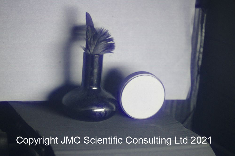
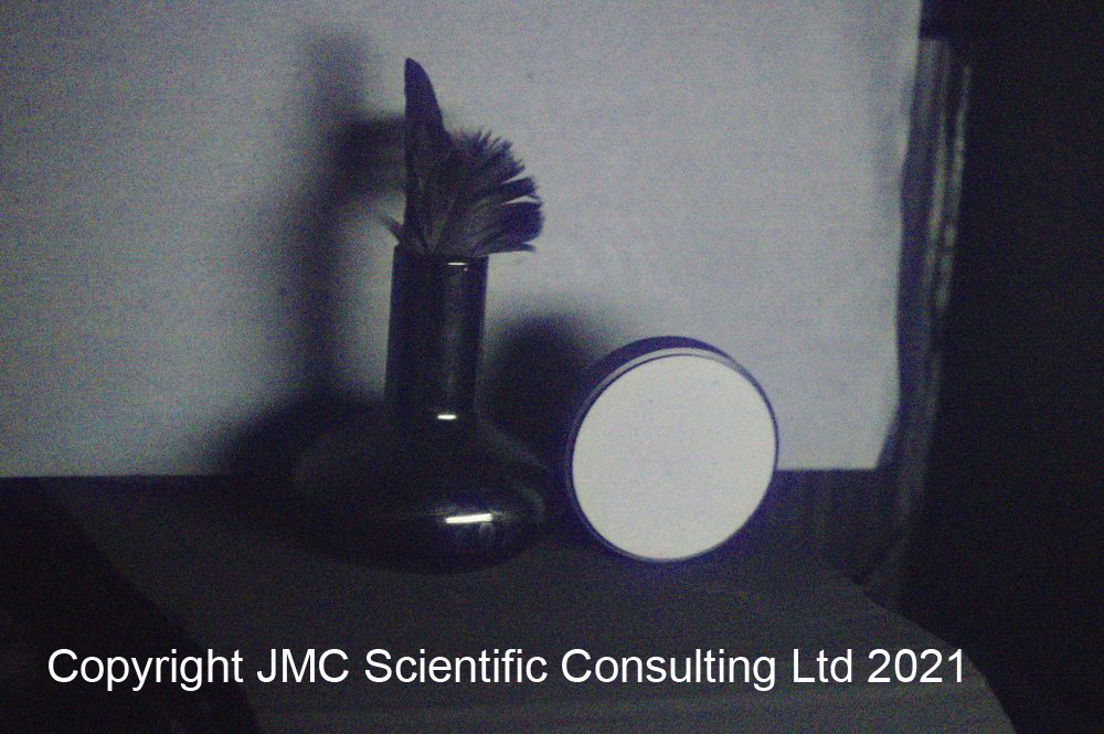
For colour imaging at 254nm, I turned to a Sony A7III which was converted to multispectral imaging again by MaxMax. When this was done I’d requested the sensor coverglass be replaced with a quartz window, instead of being left in place which is normally what happens with these types of conversions. Using the came setup as discussed here, an image of the feather in a vase was captured along with the diffuse reflection standard. After white balancing this was how it looked.
254nm image captured using a converted Sony A7III camera.
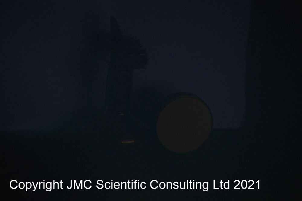
As before I captured an image with a Schott WG305 filter as well to see how much of the image was coming from longer wavelengths, and here’s how that looked.
254nm image captured using a converted Sony A7III camera and WG305 filter in place.
As with the monochrome camera, a faint image was seen with the WG305 in place, indicating what I was capturing at 254nm was not a pure 254nm image, but that there was some contributions from longer wavelengths. However the majority of the image was indeed coming from reflected 254nm light.
I was really surprised with the performance of the Sony A7III and the fact that I could get an image at 254nm with it, with the Bayer filter still in place. Given how much UV was absorbed at 308nm by the Bayer filter, I’d fully expected this to be the case at at 254nm, however it does not seem to be the case, and initial assessment of the images suggests that the Bayer filter is absorbing less of the light at 254nm than it does at 308nm, although this remains to be proven. Hint, hint, if anyone can deposit Bayer filter dyes on to a quartz plate at thicknesses which are representative of their usage on camera sensors let me know…..
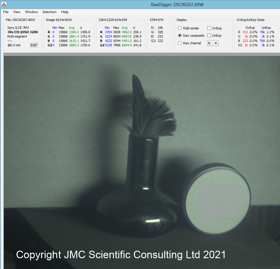
It is possible to get some idea of how the different colours in the Bayer filter are transmitting the light from RAW files. Looking at a 308nm image in RawDigger as a Raw composite file you get a distinctly green colour cast to an image taken with a multispectral converted camera, as shown below.
308nm image from a multispectral converted Canon EOS 5DSR.
The image above was taken with converted Canon EOS 5DSR camera using an Invisible Vision 308nm filter. The Raw composite file has a distinct green colour cast at this wavelength, showing the green parts of the Bayer filter have a better transmission here than the red and blue parts. Oh and do not go shining 308nm light on your skin, without doing an extensive safety assessment. You have been warned…..
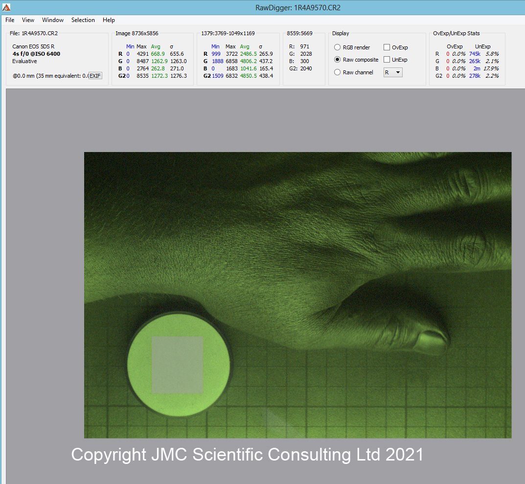
The Raw file from the Sony A7III at 254nm looked like this.
254nm image from the multispectral Sony A7III camera.
At 254nm the green channels response from the diffuse reflectance standard are still slightly higher than red and blue ones, but there is much less difference between them all at this wavelength when compared to 308nm. As a result the Raw composite image has much less of a colour cast to it. This would suggest that the red, green and blue dyes have much more similar transmission to each other at this wavelength than at 308nm, although that remains to be proven.
One final thing before I end todays post. The Sony A7III has a quite amazing high ISO performance, so after I’d taken the images above I cranked up the ISO to 102,400, and took an image at 254nm with a 1 second exposure time!!!
254nm image with the converted Sony A7III at ISO102,400 and a 1s exposure.
While obviously noisy, the image at ISO102,400 is quite frankly astonishing, especially when you consider that this was a 1 second exposure at 254nm.
Yet again I have been amazed and surprised by how far into the UV region it is possible to look with what are at their heart commercial high street cameras. Even with the Bayer filter and microlenses in place, it was possible to capture images at 254nm using a converted Sony A7III camera. Thanks for reading, and if you want to know more about this or any other aspect of my work you can reach me here.