
For a few months now I have been working on converting an Olympus BHB microscope to create something that I can use for UV microscopy down to below 300nm. This will be of use with my work on skin and sunscreen development as well as other areas. As can be seen here, the existing optics of the BHB very effectively block the UV below about 340nm which means the microscope needs modifying for it to be able to do this. To make it UV capable below 340nm means getting rid of all the glass optics and replacing them with UV transparent items such as UV fused silica, quartz and calcium fluoride. I’ve been providing updates as I’ve been doing the work on different aspects of it, but these are spread across a number of posts. I think it is time now to give a bit of summary about where I have got to, and also discuss the latest part of the work – replacing some of the optics with UV fused silica lenses.
Summary first, and I’ll give links to other pages which go over the topics in more details. In the Olympus BH series brochure (from Alan Wood’s excellent Olympus site) there is a nice cross section of a BHB microscope, and this is shown below.
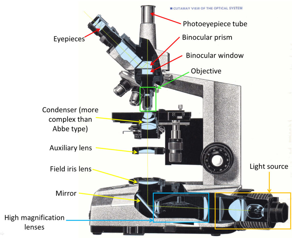
With the cross section above I’ve added some labels to help explain the areas I’ve been working on with the UV conversion. Colours are purely there to help identify each section.
Starting at the light source (lower right). The conventional light source is Tungsten filament bulb which gives no UV. The aim will be to use either xenon or mercury xenon light sources for the UV imaging, as shown here. I may also use LED’s especially for the 365nm imaging, but not sure yet on that.
After the light, there is a set of lenses used for high magnification work. These can be moved in and out the beam as needed, depending on the objectives being used. These are glass, and I wont be replacing them, basically because I don’t need to. Some of the mercury xenon lamps I have are focusable, which means I can focus the light without needing these additional lenses, so I can just leave them out of the beam when they are not needed. This cuts down on cost and complexity for me.
After the high magnification lenses there is a mirror which turns the light through 90 degrees. That mirror is actually a good UV reflector so I am leaving that as it is. Then we come to the field iris lens, the auxiliary lens and the condenser, as discussed here and here. All of those are being replaced with UV Fused silica versions, and this will covered in more detail in the second half of this post. The condenser I am building is a simple one with just 2 lenses (simpler than the one shown in the image above).
Above the condenser, but not shown on the diagram is where the slide sites. Even that and its coverslip need to be made of UV fused silica or quartz, as discussed here.
Above the slide is the objective. I’ve written a few pages on these, as I have a range of different ones which can be used for imaging below 300nm. These include the Leitz 16x UV, Leitz 40x UV and 100x UV, Lomo 10x UV, and some others such as Beck reflecting objectives and a 32x Zeiss Ultrafluar which I have not written about yet on here.
Above the objective sits the binocular/trinocular head. I’m going to be swapping out the window and part of the prism for UV fused silica as mentioned here and parts have been ordered for that from UQG Optics. In the top part of the head is the photo eyepiece. Even this needs to be changed from the normal Olympus ones, and I’ve got a range of Lomo ones which are made from quartz as shown here.
After that comes the filters for selecting the UV wavelengths to be imaged and the camera, but that is a whole different issue and will be discussed another day. Phew, we got there in the end, but I hope that gives you some idea of the complexity of converting a microscope to be able to image UV down below 300nm.
Now the the latest update. As mentioned before, part of the conversion requires replacing the field iris and auxiliary lenses, and also the condenser assembly (which in its simplest form on the BHB has 2 lenses which I refer to as ‘Abbe top’ and ‘ Abbe lower’). UV fused silica parts for these came from a couple of optical suppliers in the UK – Laser2000 and Knight Optical – based on what was available from the ranges they had without things needing to be custom made (to help keep costs down). Let’s start by looking at the transmission spectra of the 4 lenses, as measured using my Ocean FX spectrometer and the lens transmission setup I designed.
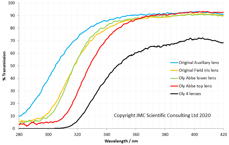
As can be seen above the 4 lenses cut the UV between about 280nm and 310nm, and when looked at together are effectively blocking everything below about 320nm. Obviously no good for UV imaging below 300nm. This transmission is similar to the modeled data shown here, and given that there were a lot of assumptions in that model, it is not surprising that it isn’t a perfect match. So what do the UV fused silica replacement lenses look like?
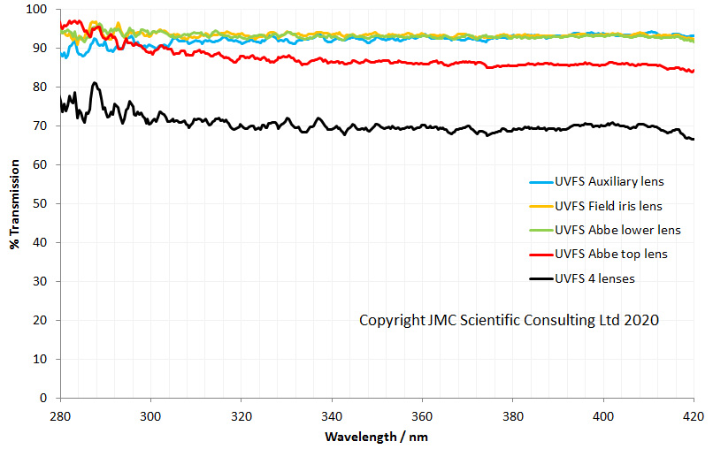
The UV fused silica lenses have essentially flat transmission spectra down to 280nm which is far as I can currently measure the lens transmission. However based on the specs for the fused silica, they would be good for use down to 250nm and even below.
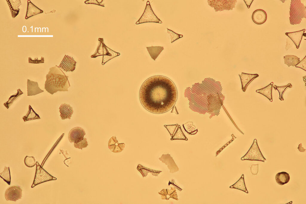
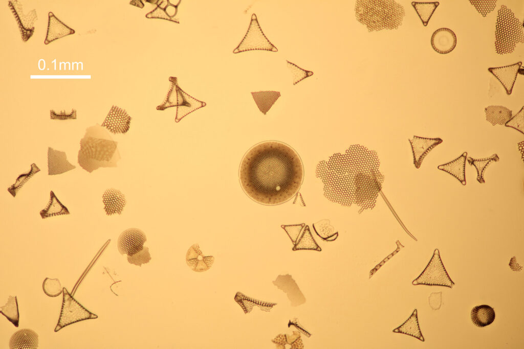
Success. I now have 4 replacement lenses which will transmit the UV below 300nm. But the big question, do they work – can I get an image using them if I mount them in place of the existing Olympus lenses? For this test I just did a brightfield visible light image (this is purely a test of whether they can control light in a manner by which I can generate images of a subject, so at this stage of testing UV is not needed). For this I used a strewn slide of Simbirsk, Russia diatoms from Diatom Shop (very high quality mounted slides) and an Olympus 20x Splan objective. Images were stacked in Zerene (Pmax method). No additional sharpening or image modification has been done to enable comparisons to be made more easily.
Firstly, with all the original lenses still in place (these are low res versions of the original images).
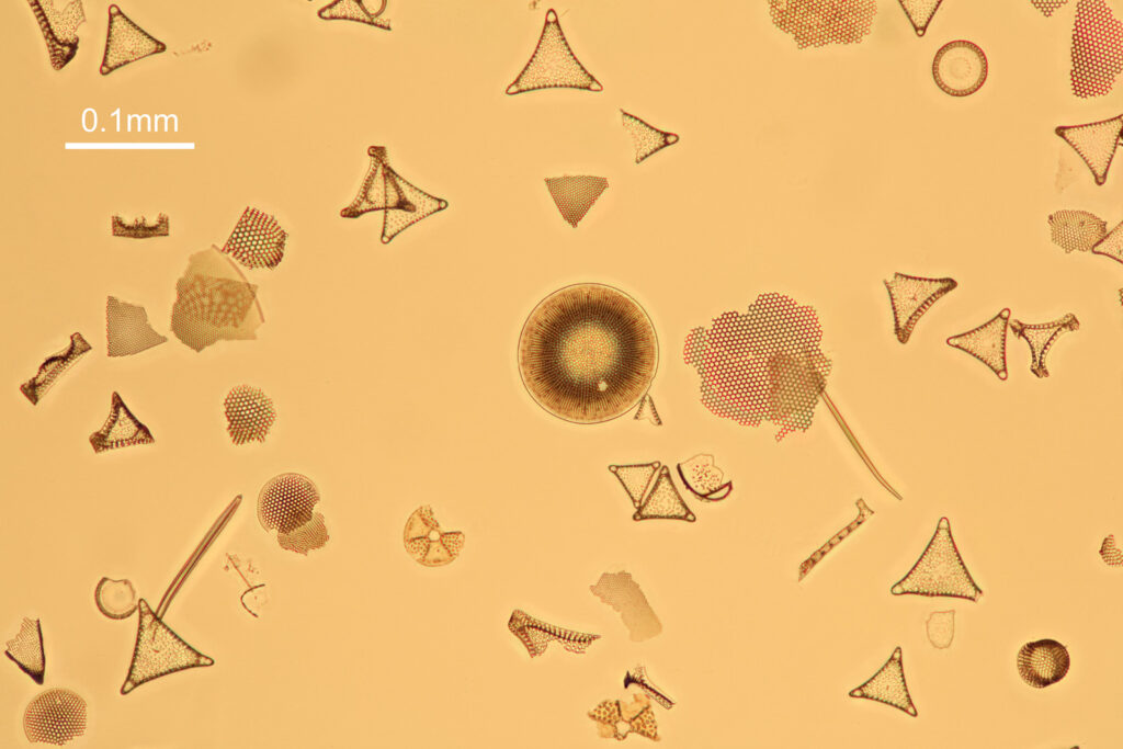
Now, the same slide imaged with all 4 lenses replaced with UV fused silica ones.
And then finally an image taken with the UV fused silica field iris lens, and the other lenses kept as original Olympus ones (as I want to be able to use this microscope for normal visible light work too and didn’t want to compromise its functionality).
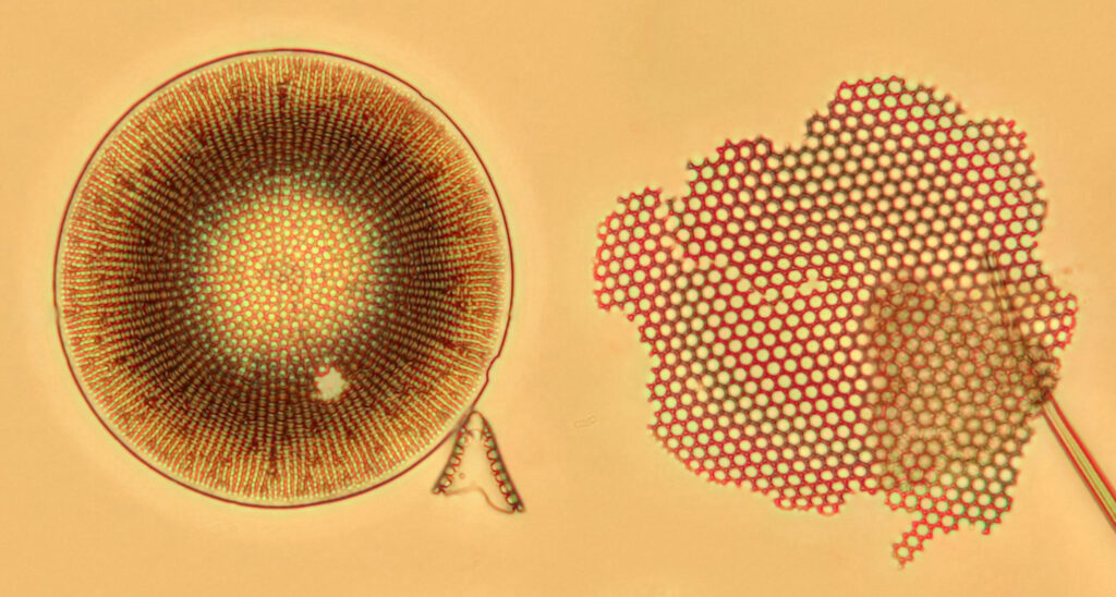
The good news is that the replacement UV fused silica lenses still allow me to capture images. On the low resolution images above it is difficult to draw comparisons between the different setups, although the UV fused silica lens image looks to be a little lower in contrast. However I also created a set of cropped images from each of the original ones, and they are shown below at actual pixel resolution. Firstly, all 4 original Olympus lenses.
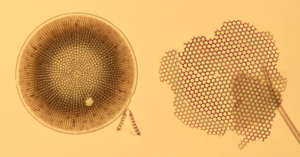
Next, with all 4 UV fused silica lenses.
And finally, with the UV fused silica field iris lens, and the auxiliary lens and condenser as standard Olympus components.
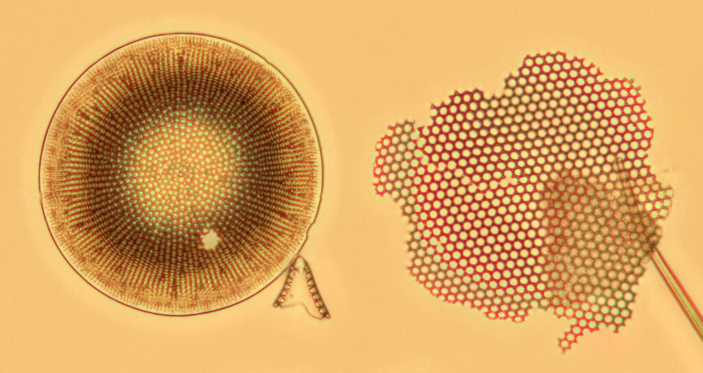
What is going on here? Firstly replacing the field iris lens with a UV fused silica one (but keeping the Auxiliary lens and Condenser standard), I get a very similar image to when the field iris was left standard. Good, I can leave the UV fused silica field iris lens in all the time and still use the microscope for normal visible light work. Hurrah. Next, with all 4 UV fused silica lenses, I get a good image, although perhaps not as high contrast as with the original Olympus components. That’s ok, I can live with that as after all I am modifying a device designed and manufactured by a major microscope builder and I wasn’t expecting final image quality to be just as good. Interestingly, with the original Olympus Abbe condenser, there is evidence of strong chromatic aberration (red and green fringes) on the diatoms, but I do not see that with my UV fused silica lenses, and I’m not sure why at the moment. I somehow doubt I have created an APO lens setup, so more work needed to look into that.
It’s been a bit of a large update today, but I thought it was necessary to try and bring everything together as there is so much work that has gone in to getting this far. The UV fused silica lens replacements have enabled me to create an image, and of course their transmission will allow me to work down below 300nm once the final few components for modifying the binocular/trinocular head arrive towards the end of the year.
I’ve been told I am a bit mad (in a light hearted way I hope – anyway, I prefer the term ‘eccentric’) for trying to modify a microscope to image down below 300nm, and that starting with an Olympus BHB was not the right way to go about it. However by using this microscope it has been possible to modify and dismantle and reassemble it easily, something which wouldn’t have been possible with a more recent ‘plastic’ microscope. It certainly hasn’t been straightforward so far but if I look back over the last 8 or so months, it’s made me learn loads about a whole new area of research. It’s that drive to learn new things that keeps us as scientists going, and while yes I’ll use this for research in future, the learning of new things is in itself a worthy goal.
Thanks for reading, and if you want to know more about this or any other aspect my work, please contact me here.