I’m a big fan of using equipment in ways it wouldn’t have been used to solve a problem, and today’s post is an example of that.
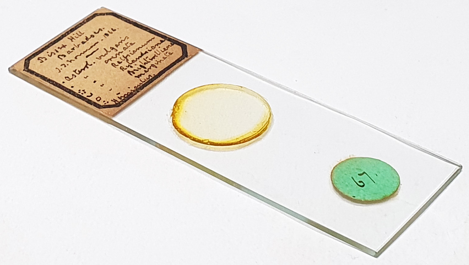
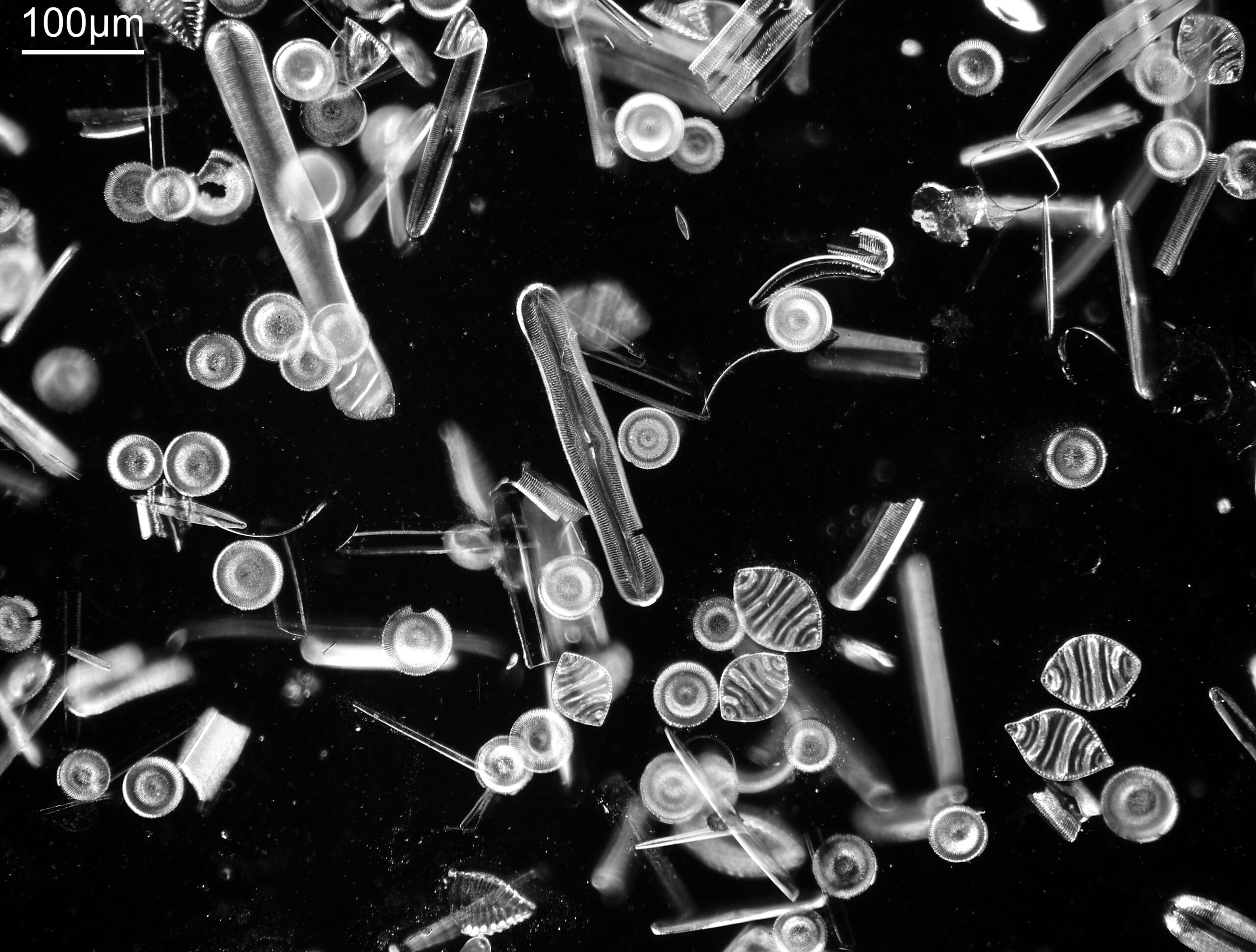
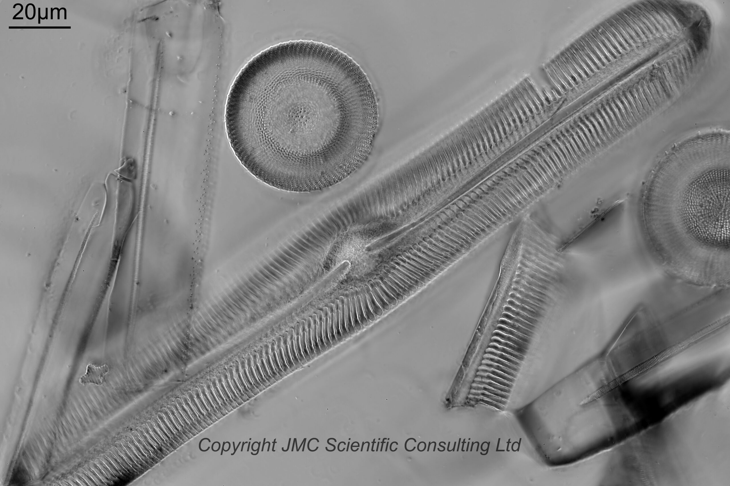
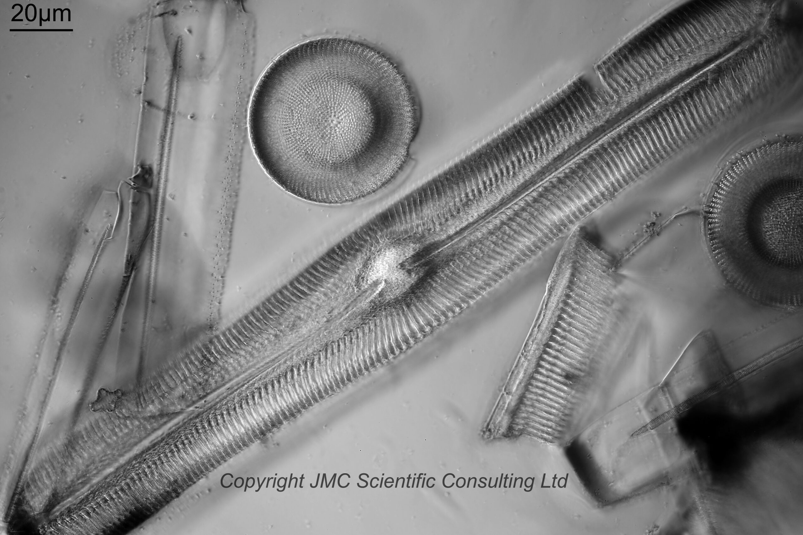
For background, I have a nice microscope diatom strew slide from Bissex Hill, Barbados, which was prepared by JT Norman in 1866. Lovely slide, lost of species, a great to look at. However it has a problem. The coverslip seems to be very thick and/or the diatoms are mounted very deep. As such my usual ‘go to’ high magnification objectives (40x and 63x Leitz Pl Apo oil immersion ones), can’t be used as they do not have enough working distance. A few weeks ago I tried using a 50x Leitz Fluoreszenz NA 1.00 water immersion objective which has a working distance of 0.68mm, and I was just able to get some images. However they weren’t great. My thought was that if the coverslip is the main ‘thickness’ issue, the refractive index of the glass would be very different to that of the water the objective was expecting and I would get aberrations as a result. What I needed was a long working distance, oil immersion objective, with high NA and high magnification. I did try a 63x Zeiss Neofluar NA 1.25 oil immersion objective, which has a working distance of 0.65mm and it was just not quite a long enough working distance to be usable (makes you realise how deep these diatoms are).
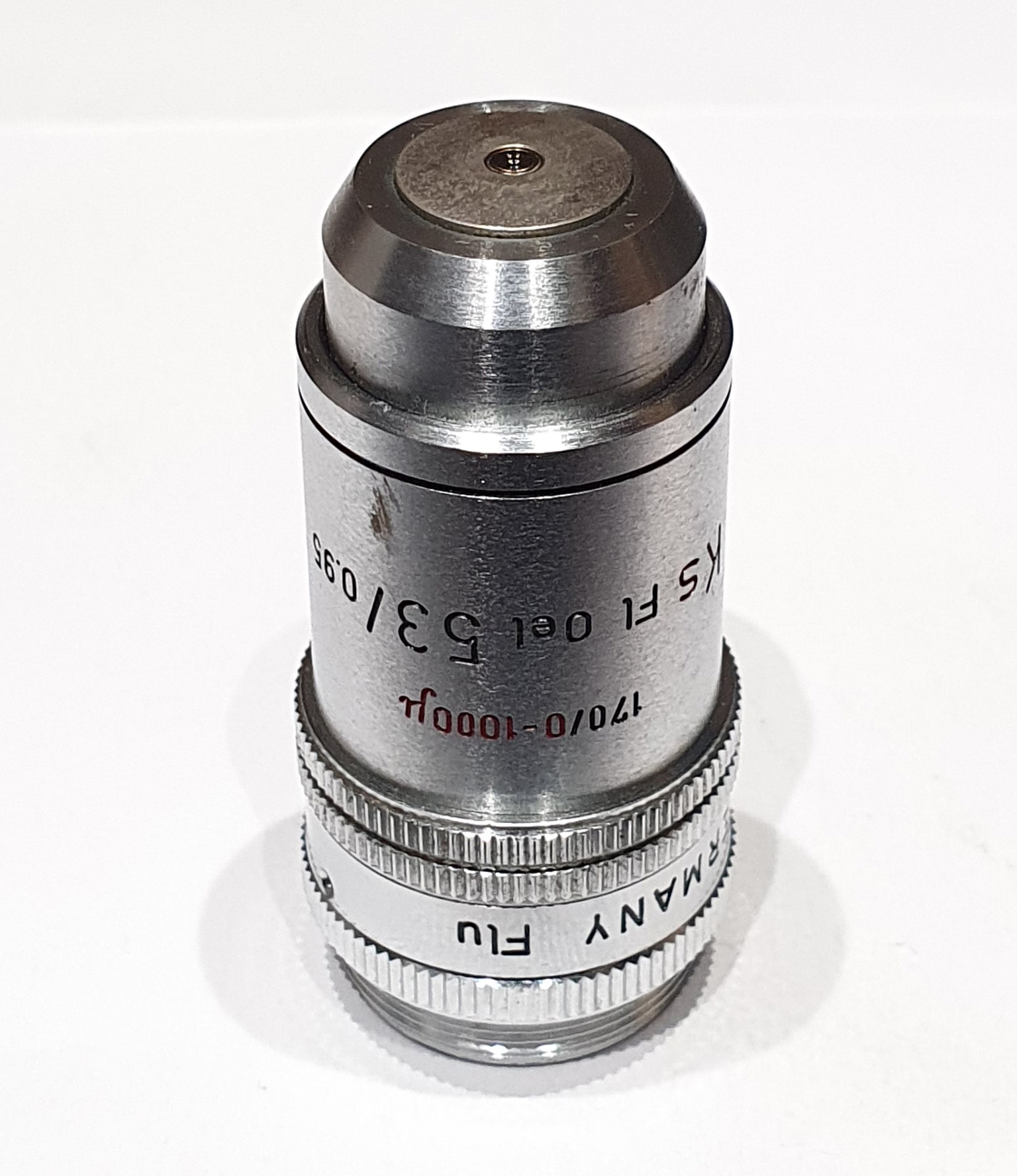
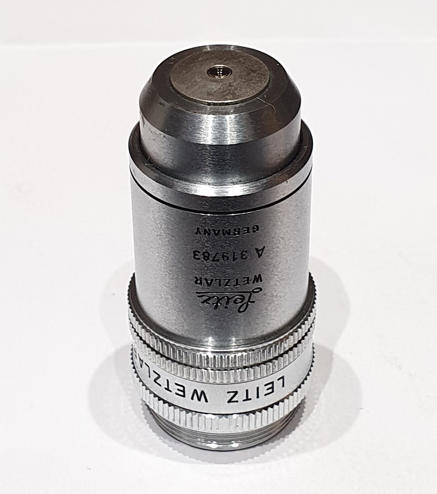
I then had a bit of sit down and think, and remembered I had a 53x Leitz Ks Fl objective, which is NA 0.95 (relatively high) and oil immersion, and was designed to look at photographic emulsions up to about 1mm thick. Oil immersion, high NA, and an enormous working distance. Woo hoo. Only problems – it is 170m tube length and my microscope is 160mm tube length, and it is a short barrel objective, so the wrong parfocal length to my normal ones. The tube length issue is not ideal, but not a deal breaker – I’ve used high magnification 170mm tube length objectives before on my microscope. The wrong parfocal length is also not a huge issue, as a I have a Plezy Flu adapter from Leitz to allow short parfocal length objectives to be used on long parfocal length setups.
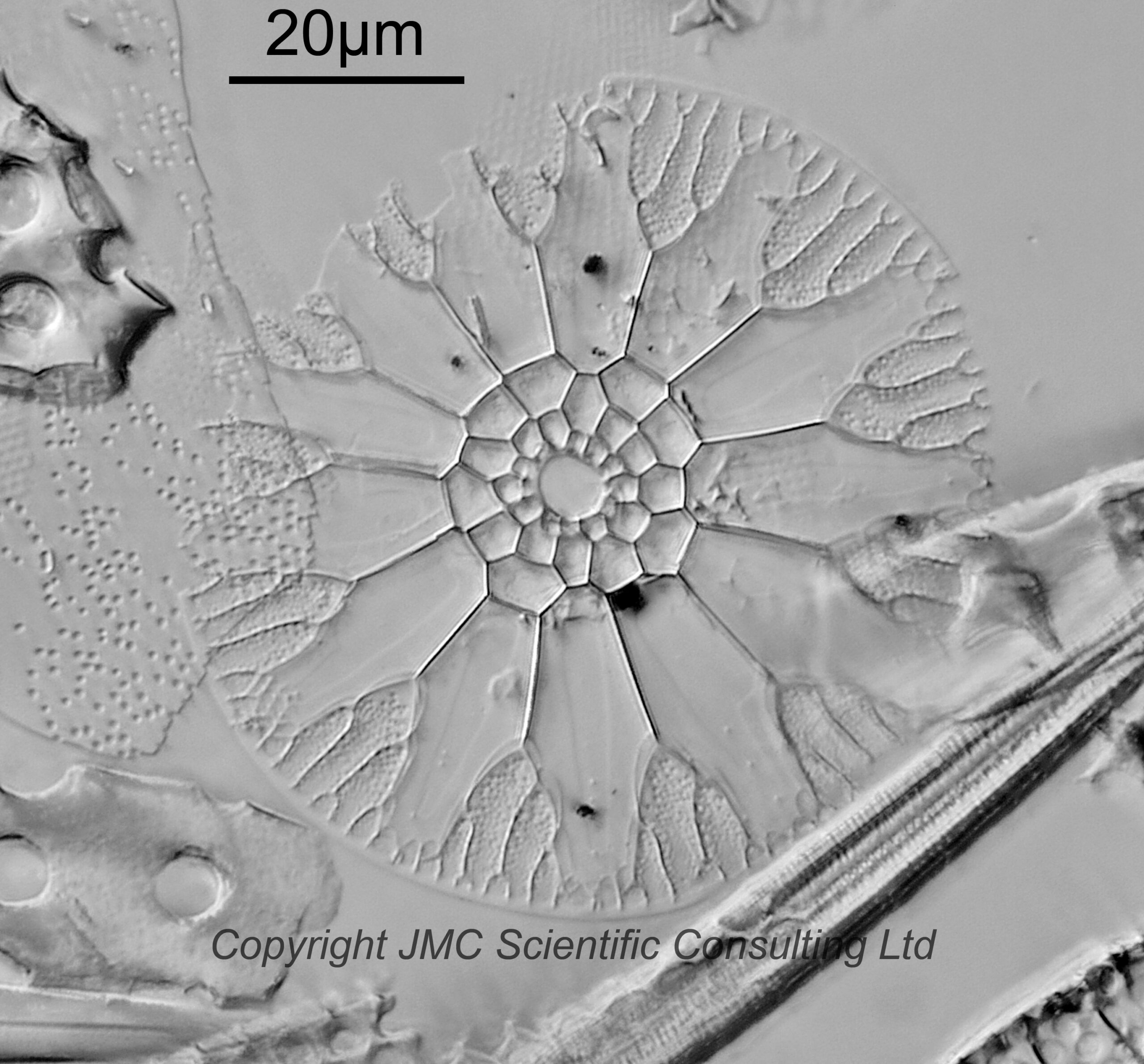
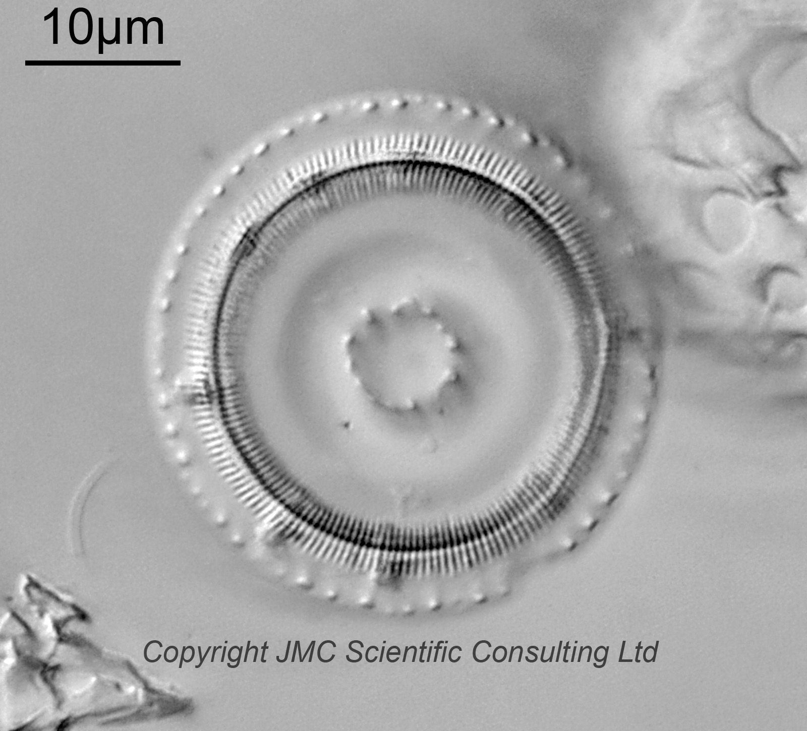
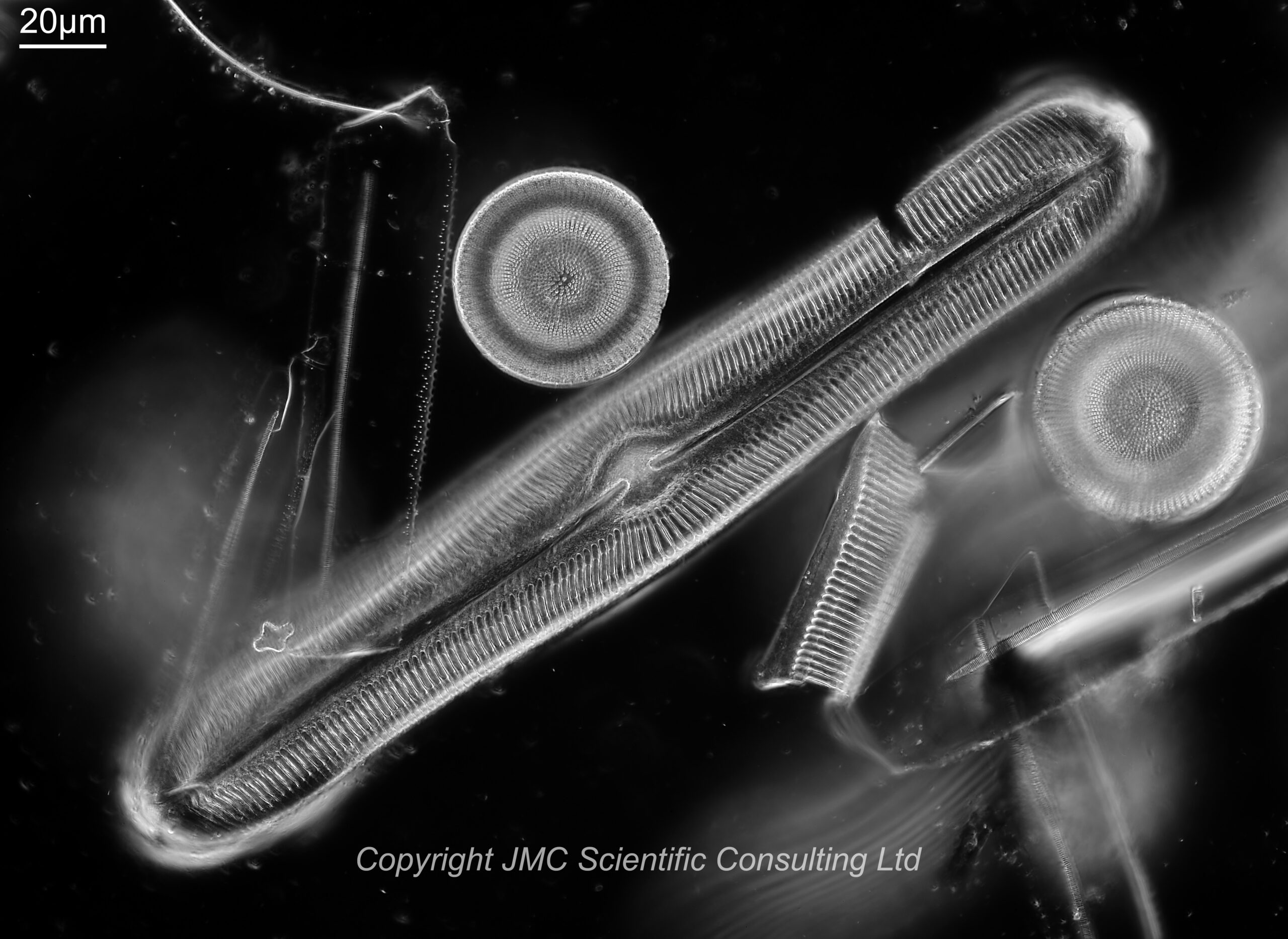
My thoughts with this was the as the objective was designed for use on photographic emulsions (including on glass) between 0.07 and 1.07mm thick, and with oil immersion, if it is a thick coverslip (which is glass with a refractive index similar to immersion oil) then ‘thick layer of oil’ would be not too dissimilar to ‘small amount of oil and thick glass coverslip’. So I set it up and tried it out, and below are a couple of examples of what it imaged.
Asterolampra ralfsiana, Bissex Hill, BarbadosPseudopodosira sp., Bissex Hill, Barbados
Overall I was very happy with the image quality. They were better than the 50x Leitz water immersion Fluoreszenz objective I had tried before. For some more images and (the original water immersion images) see the post on my online diatom museum here.
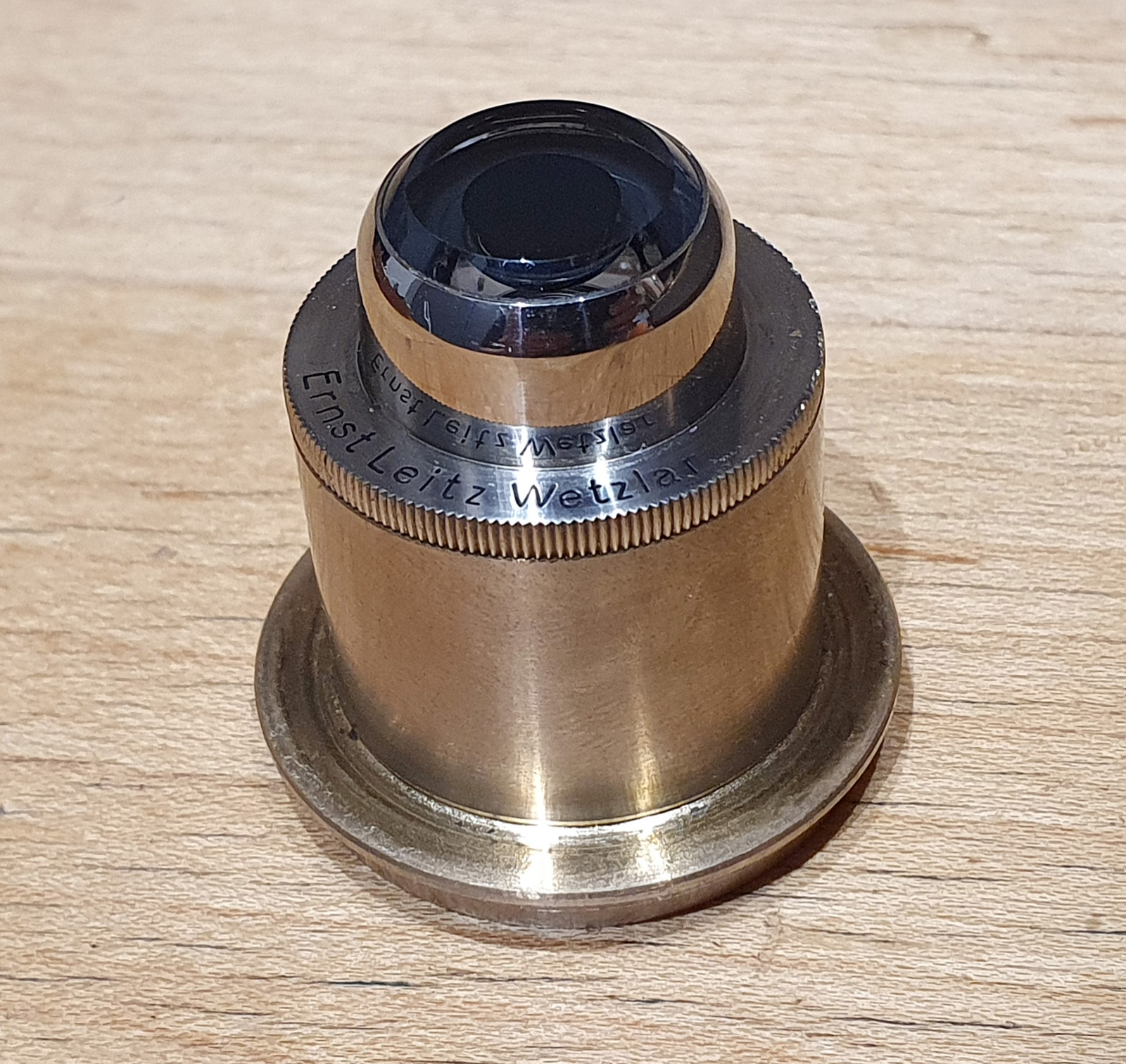
Some images of the objective and adapter.
Leitz 53x Ks Fl NA 0.95 oil immersion objective and Plezy Flu adapterLeitz 53x Ks Fl NA 0.95 oil immersion objective and Plezy Flu adapter
I’ve written a bit about the Leitz Ks objectives here.
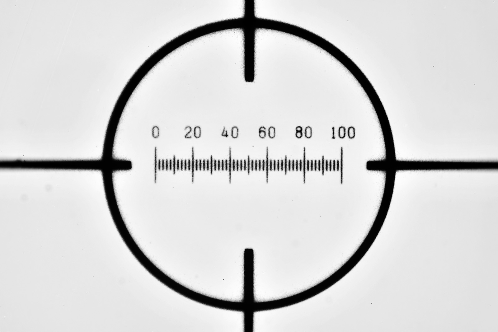
Below is an image of a 100 micron scale bar (from Graticules Ltd) taken with the objective on my setup. It is the full image frame, but reduced in resolution for sharing here.
100 micron scale bar, full frame image (reduced resolution)
Image quality is very good, especially in the middle of the image, although it does drop off at the extreme left and right which is not a huge surprise.
Before I wrap this post up, here is a picture of the slide from Bissex Hill, Barbados.
The slide
Sometimes imaging (like many scientific areas) is a problem solving challenge and it becomes important to think laterally about a an issue. This is something I love doing, and especially if I can use something outside of what it was originally designed for to get a result. As always, thanks for reading, and if you’d like to know more about my work I can be reached here.
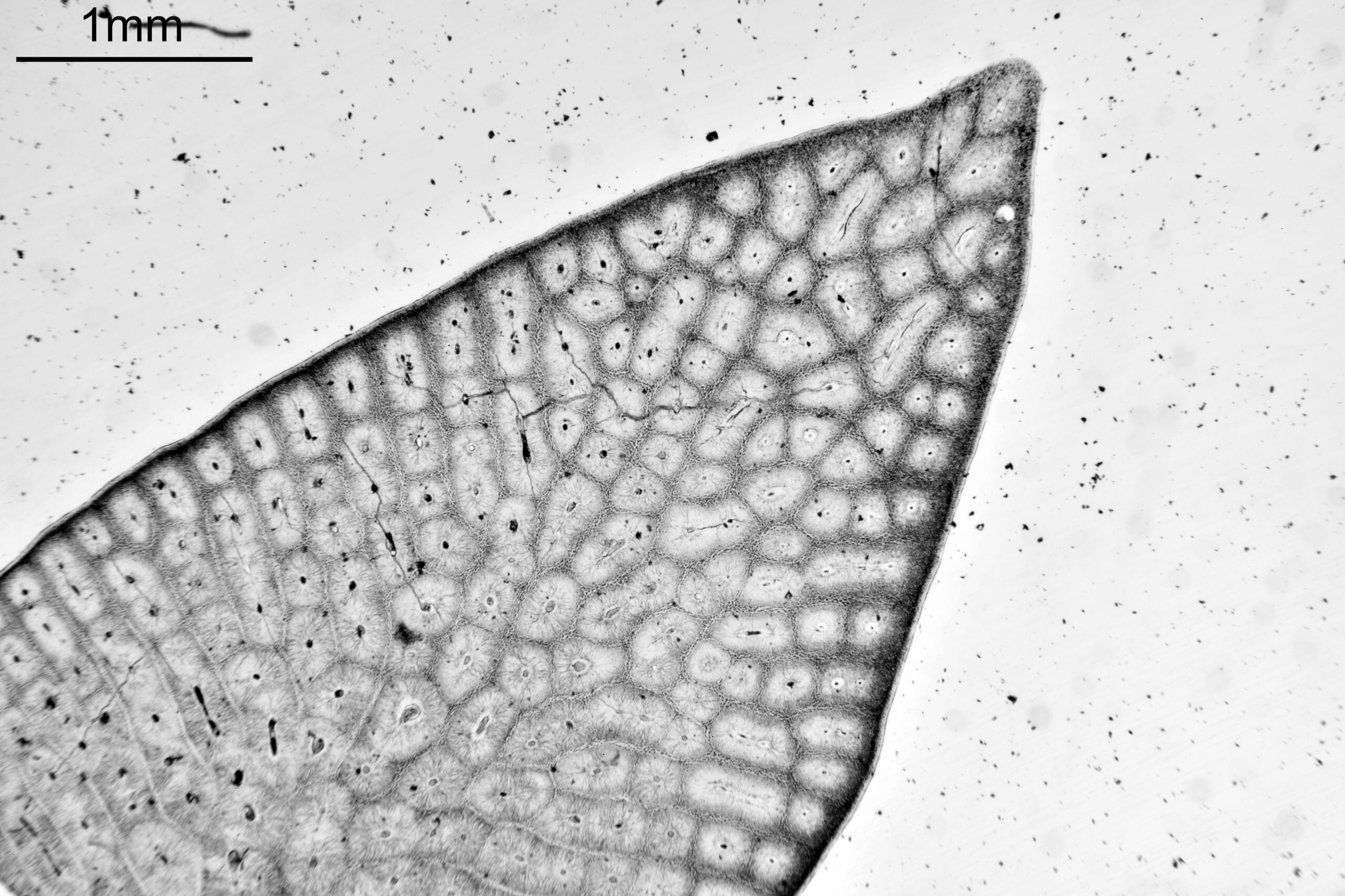
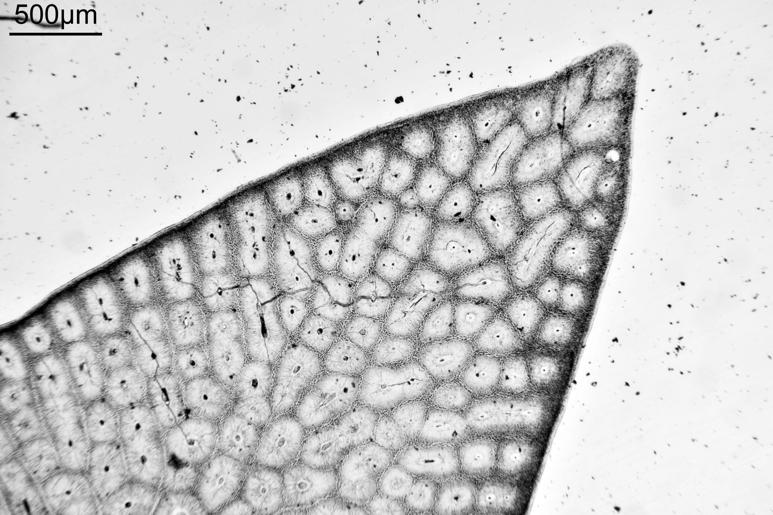
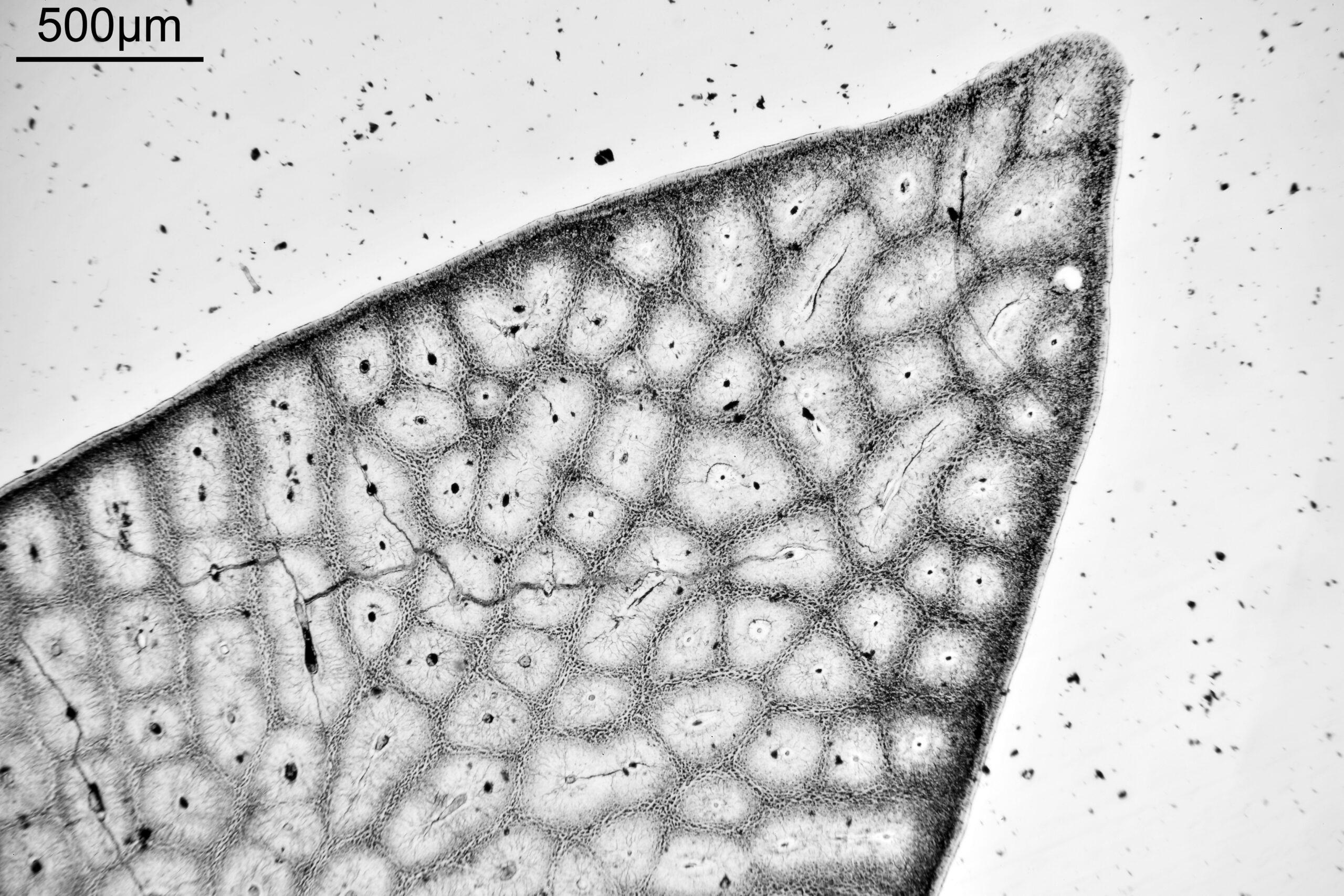
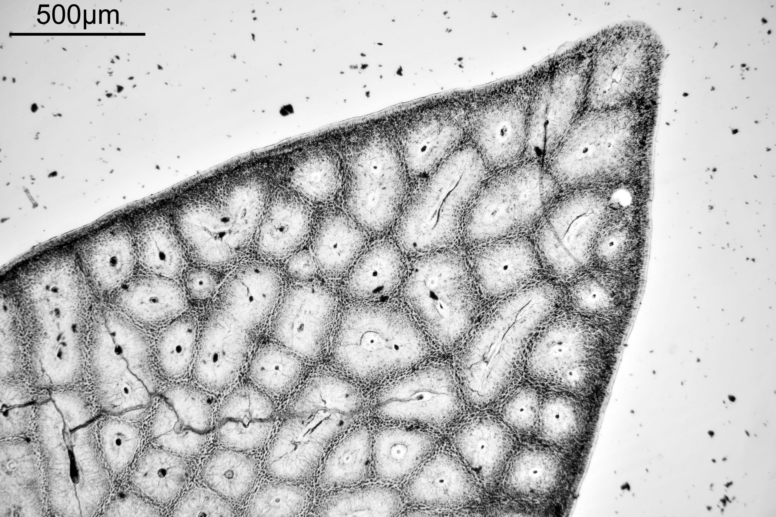
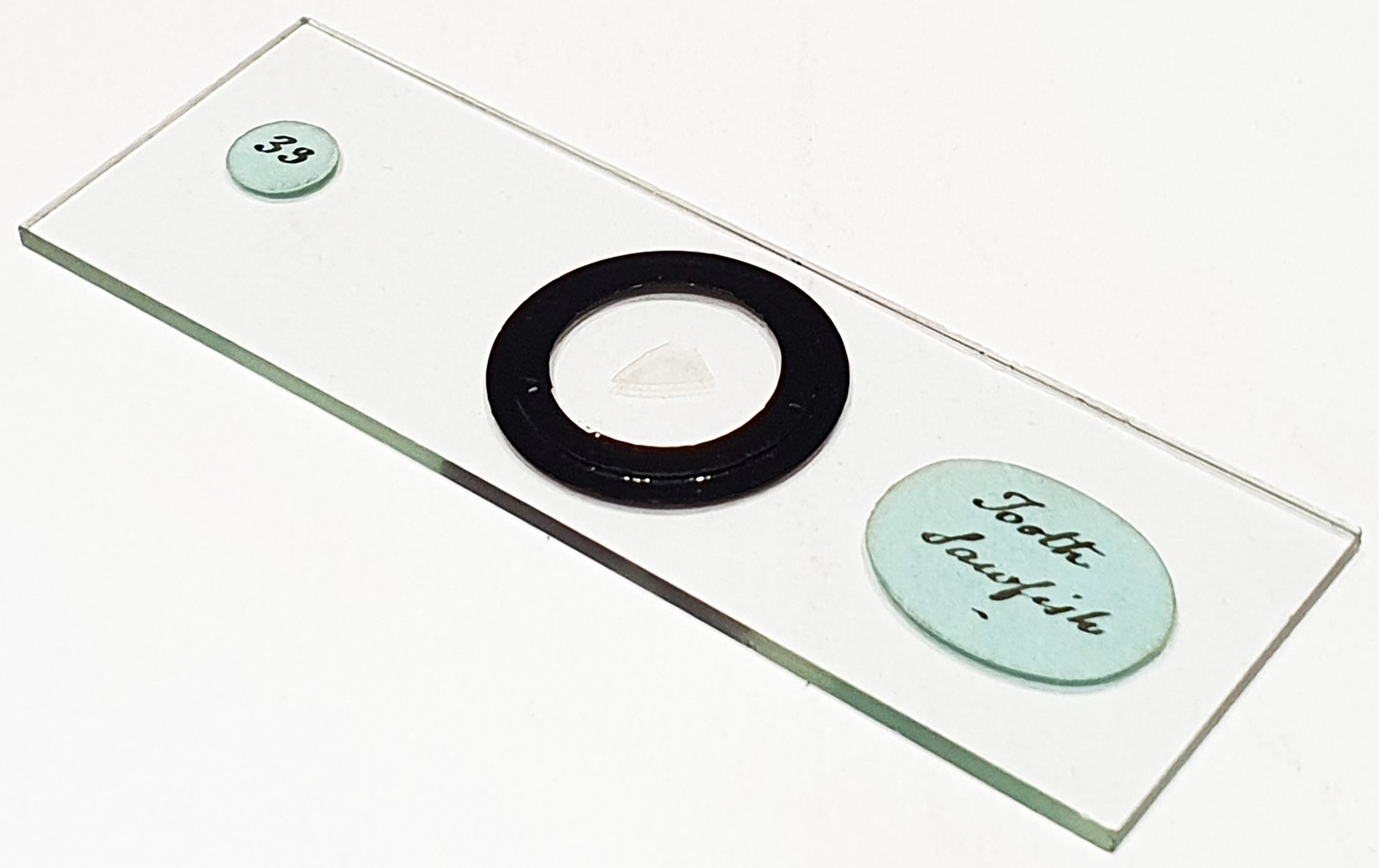
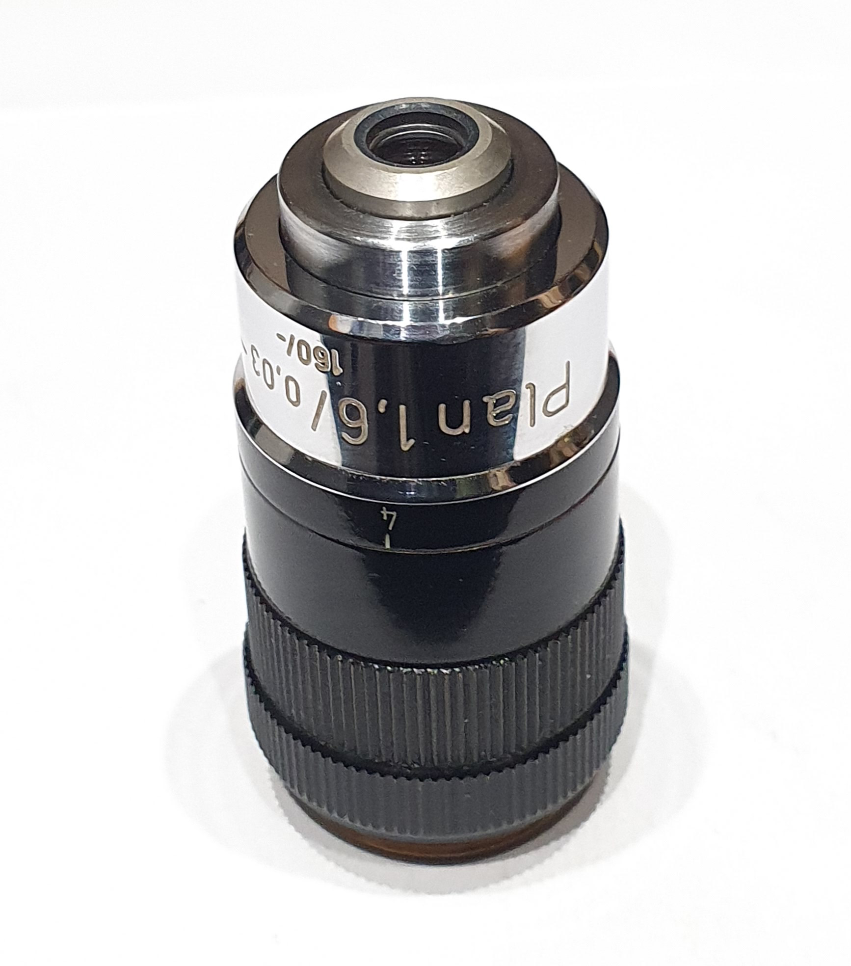
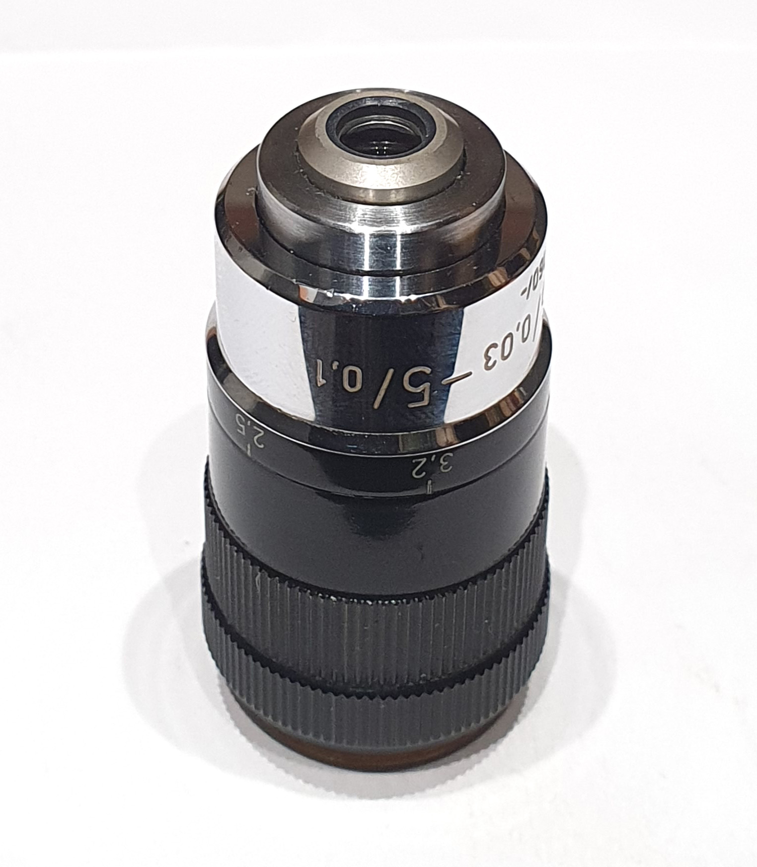
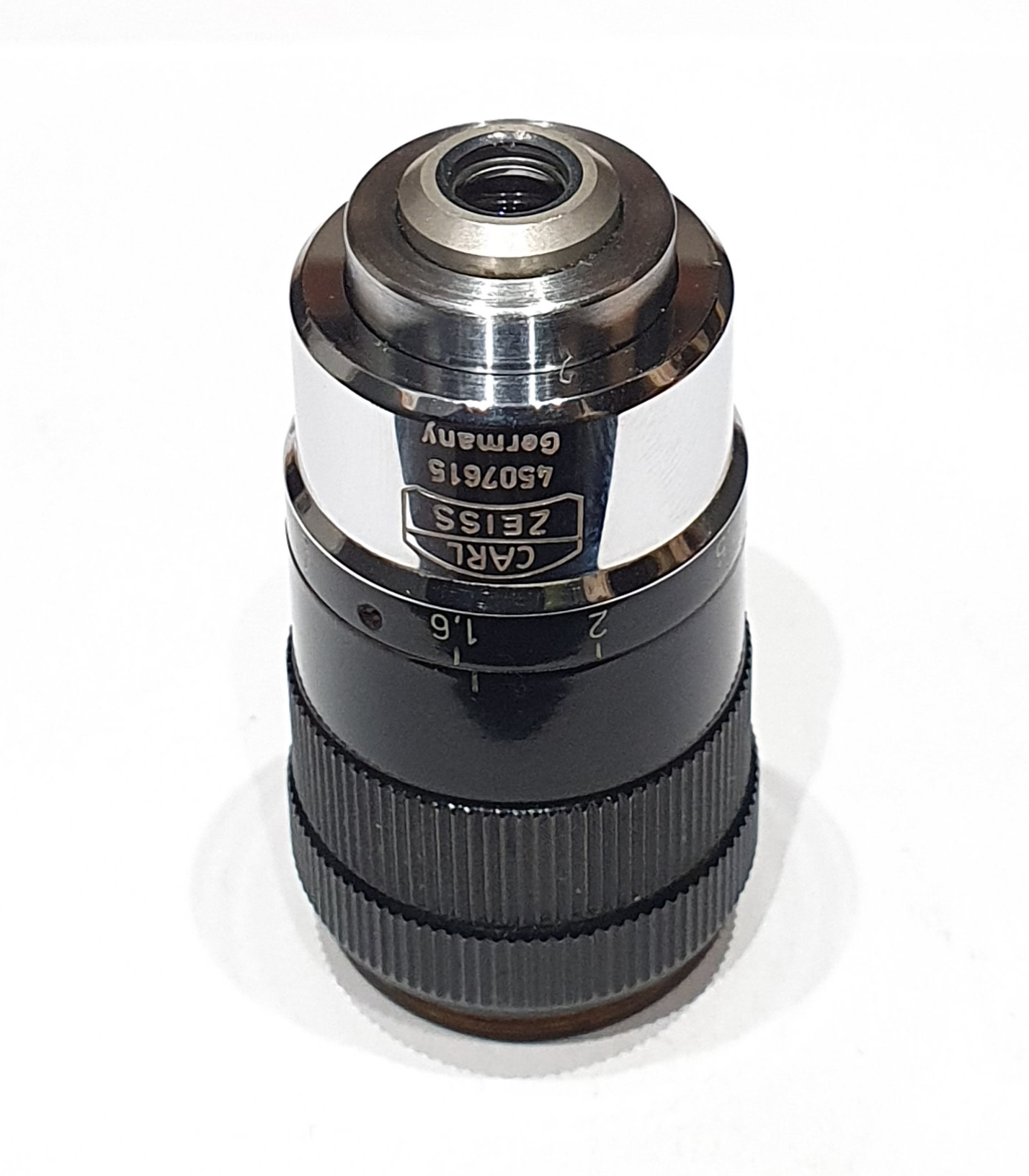
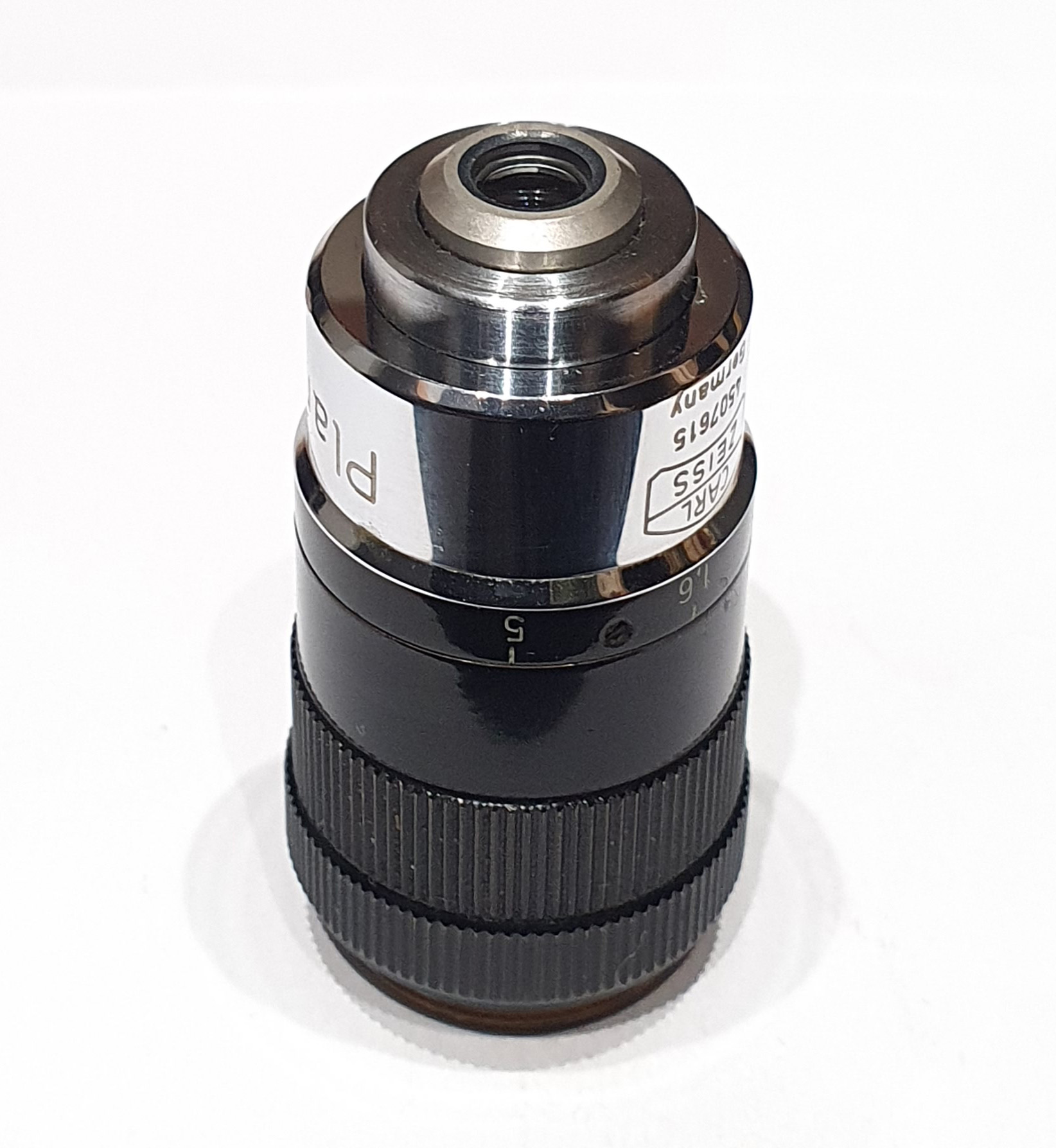
Today’s post shows a tooth of a sawfish imaged using an interesting microscope objective – a Zeiss Plan 1.6-5x zoom objective. This objective can be adjusted to give magnifications from 1.6x to 5.0x using a rotating collar. I’m sharing this as I have seen virtually nothing on this objective online.
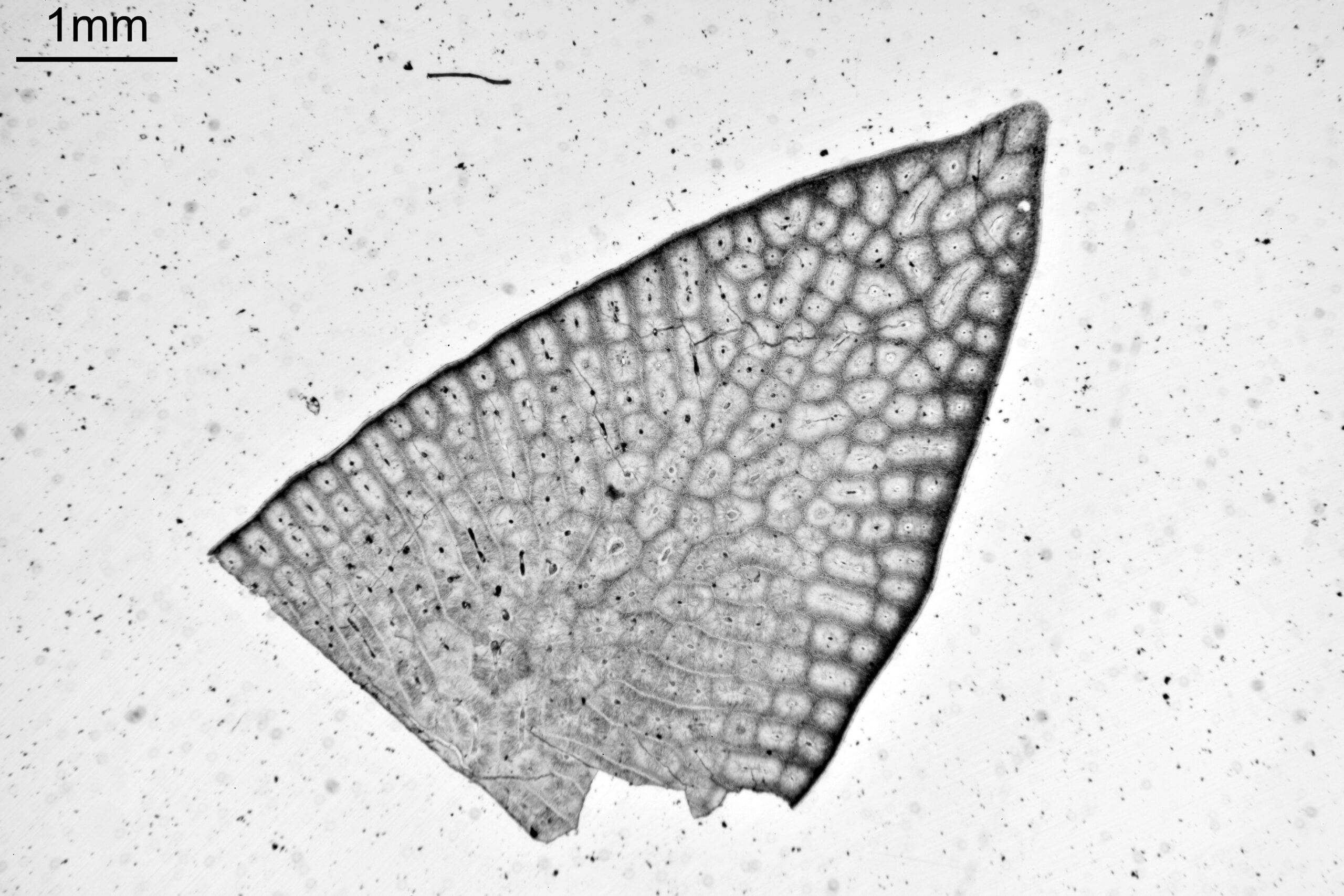
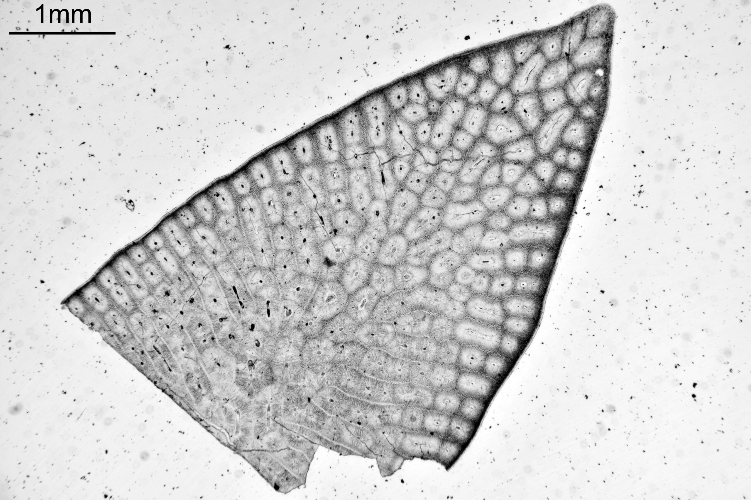
In my microscope (a modified Olympus BHB), I couldn’t get the stage low enough to get 1.6x (the lower the magnification the longer the working distance), however I was able to get to about 1.7x. Here’s a set of images of a section of a tooth from a sawfish between 1.7x(ish) and 5.0x. They have been left at the full frame from the camera (a monochrome converted Nikon d850), and simple brightfield illumination was used.
Overall, a nice performance. Not the highest NA for a given magnification (at 5x this is 0.1, vs my Nikon 4x Plan Apo which is 0.2), however a very versatile lens.
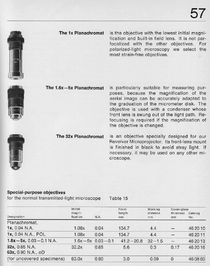
Here’s some images of the objective, and the entry from a Zeiss catalogue to provide some more information.
1971, p57, Zeiss optical systems catalogue
As always, thanks for reading, and if you’d like to know more about my work I can be reached here.
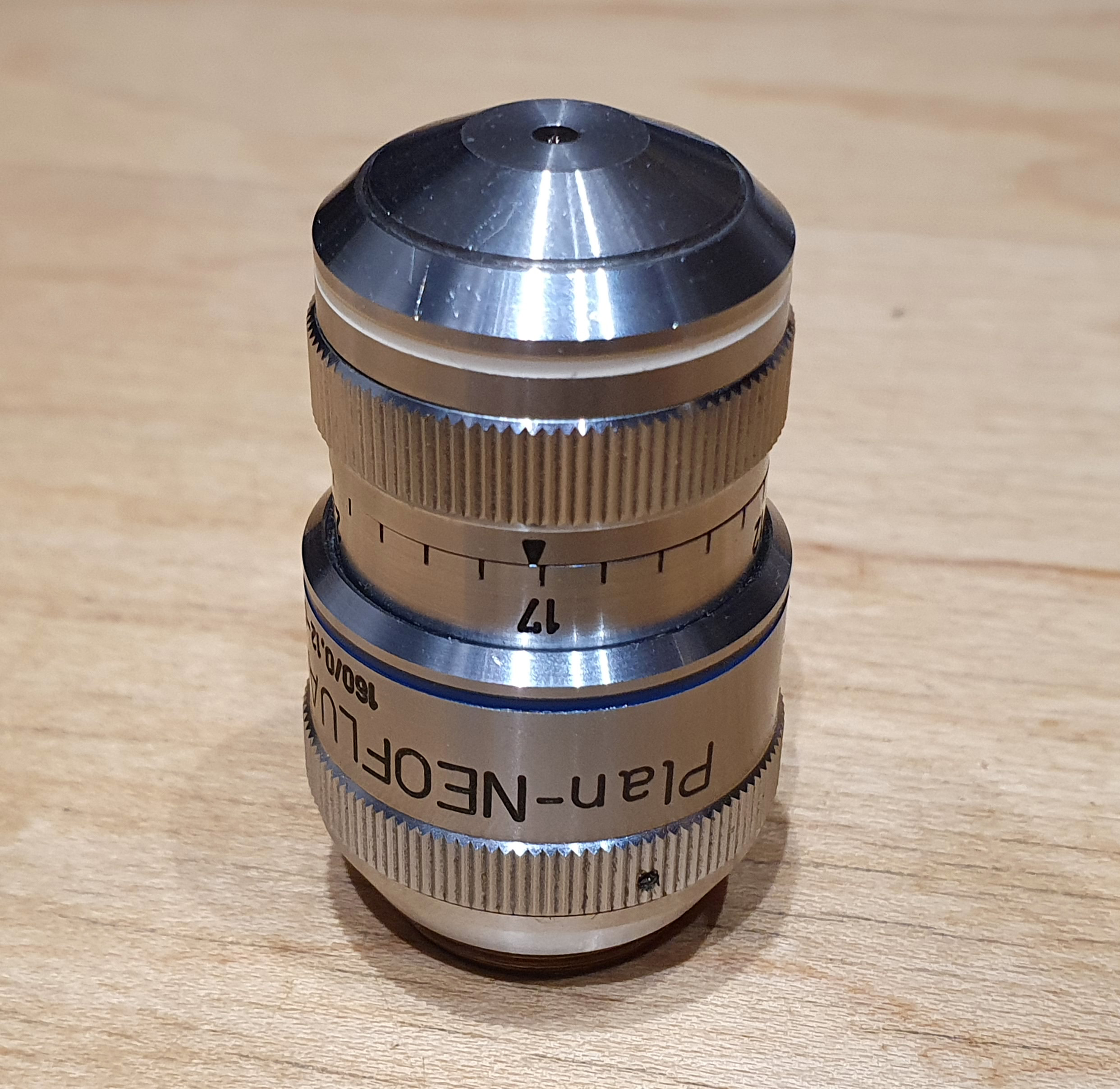
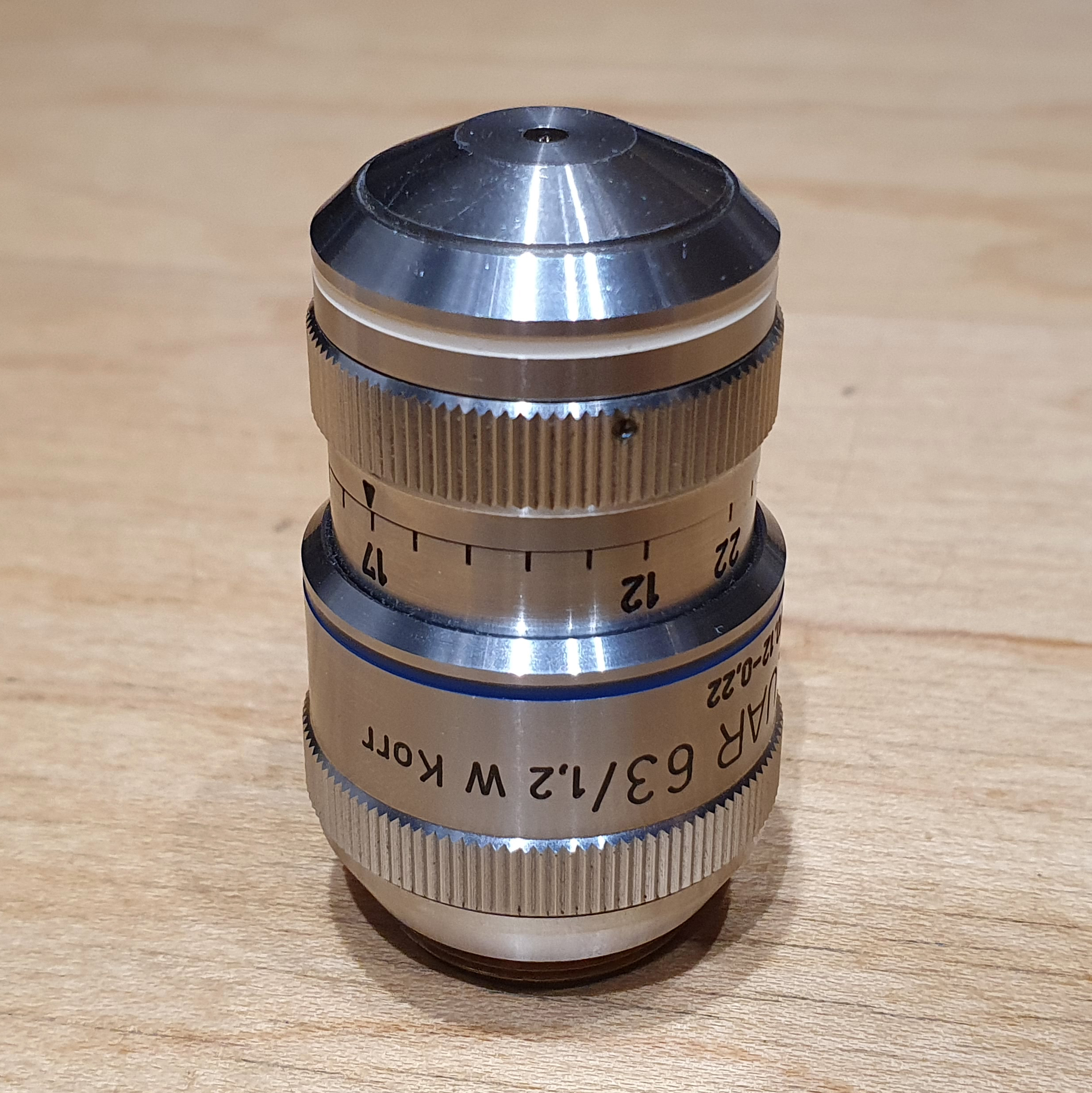
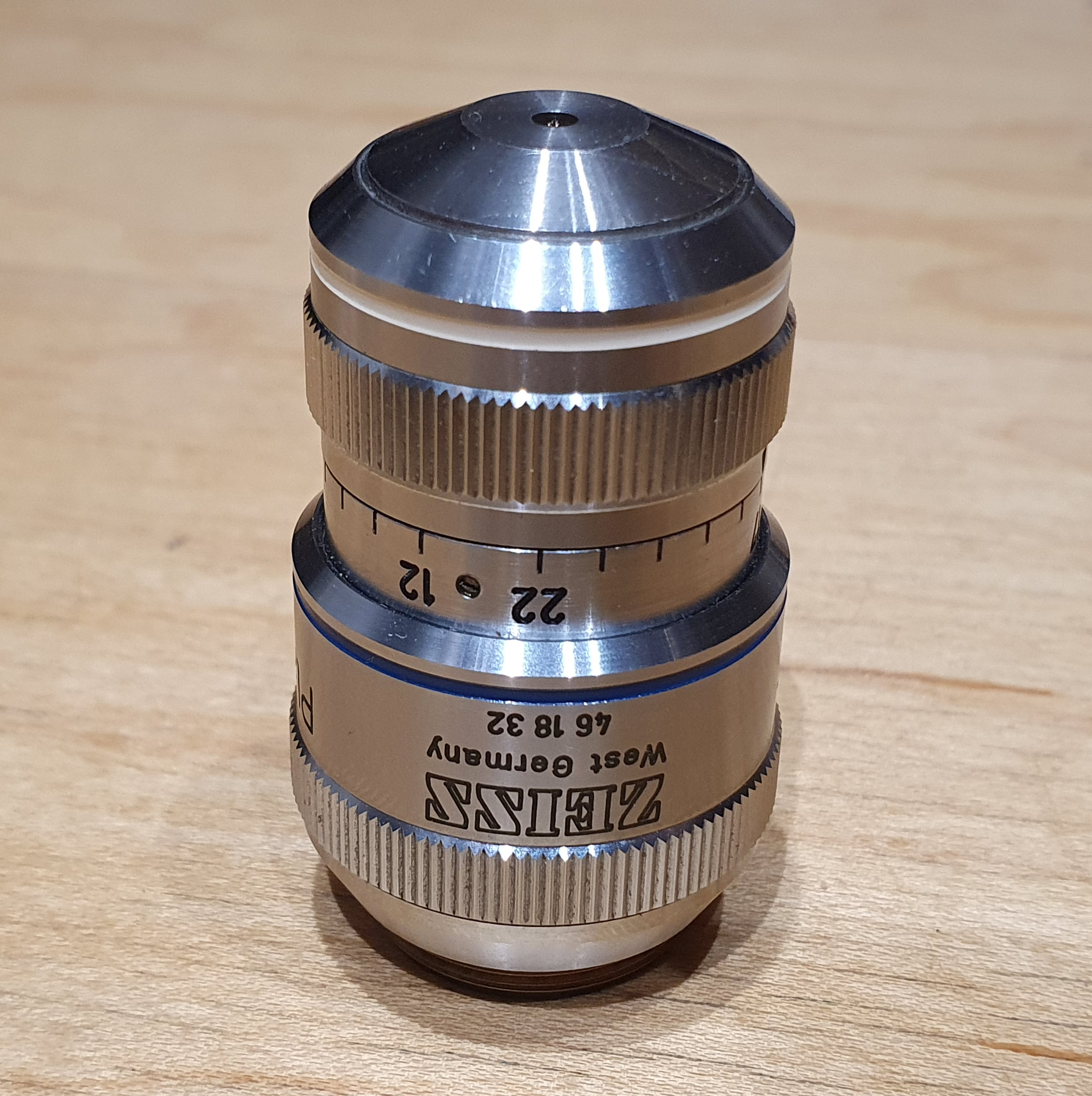
Today’s post is a look at something I had not considered before acquiring a new microscope objective – a Zeiss Plan Neofluar 63x, NA 1.2, water immersion, coverslip thickness correction adjustment. This objective has an adjustment collar for coverslip thickness, and can be varied from 0.12 to 0.22mm (shown on the objective as ‘Korr’). It becomes very important to be able to compensate for coverslip thickness with high magnification, high NA objectives, especially with water immersion, in order to obtain the best images. This is a quick look at some images from this objective, where I have changed the setting of this collar, along with an assessment of the effects of altering the collar.
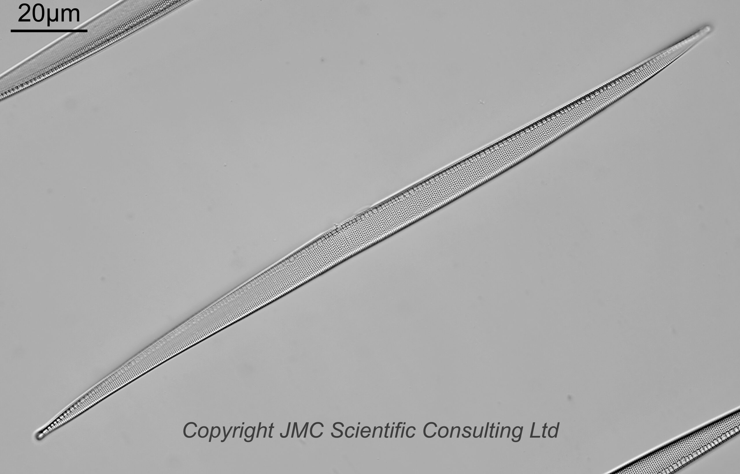
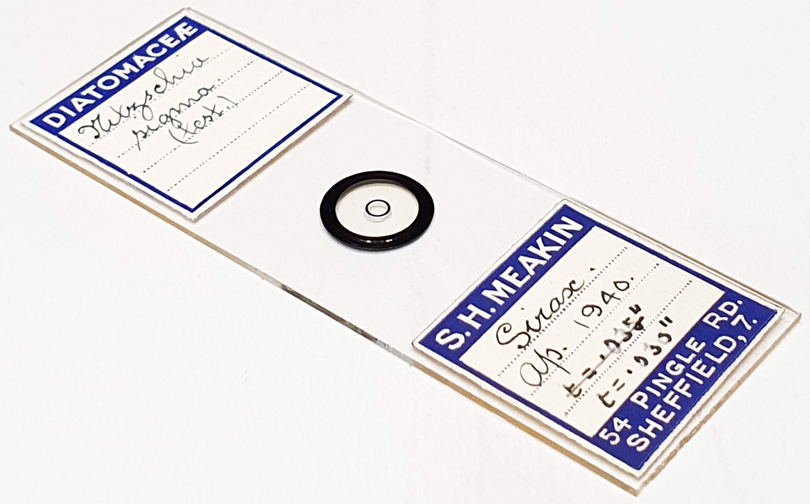
First the slide. It is a test slide of the diatom Nitzschia sigma, mounted in Sirax (a high refractive index mountant), and prepared by Samuel Henry Meakin in April 1940. The image below is a single frame (slightly cropped from the full frame, but not by much) using a 63x Zeiss Plan Neofluar NA 1.2 water immersion objective on my Olympus BHB microscope using 450nm oblique lighting.
Nitzschia sigma, SH MeakinThe slide
The diatom is fairly flat and level, so a single image shows quite a lot of it in focus. Next, the objective.
Zeiss Plan Neofluar 63x, NA 1.2, water immersion, coverslip thickness correctionZeiss Plan Neofluar 63x, NA 1.2, water immersion, coverslip thickness correctionZeiss Plan Neofluar 63x, NA 1.2, water immersion, coverslip thickness correction
The objective has a collar on it which is labelled from 12 to 22, and this is for adjusting for coverslip thickness between 0.12mm and 0.22mm. Normally coverslips are 0.17mm, however there is some variability from one to another, and sometimes thinner or thicker ones are used. Giving the user the ability to adjust for coverslip thickness allows the objective to be optimized for a given slide so the best images can be captured.
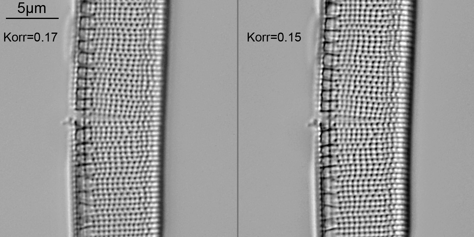
For the above slide, when I changed the setting of the collar to thicker than 0.17mm, the image quality decreased – contrast got worse. However when I decreased it to 0.15mm the contrast improved, and it then got worse again below 0.15mm. This can be seen in the image below which shows a crop from two frames, one taken at a setting for 0.17mm and the other at 0.15mm.
Coverslip thickness correction comparison
Although subtle, the image taken with the collar set to 0.15mm is slightly higher contrast than the one at 0.17mm. Both images were treated in the same way.
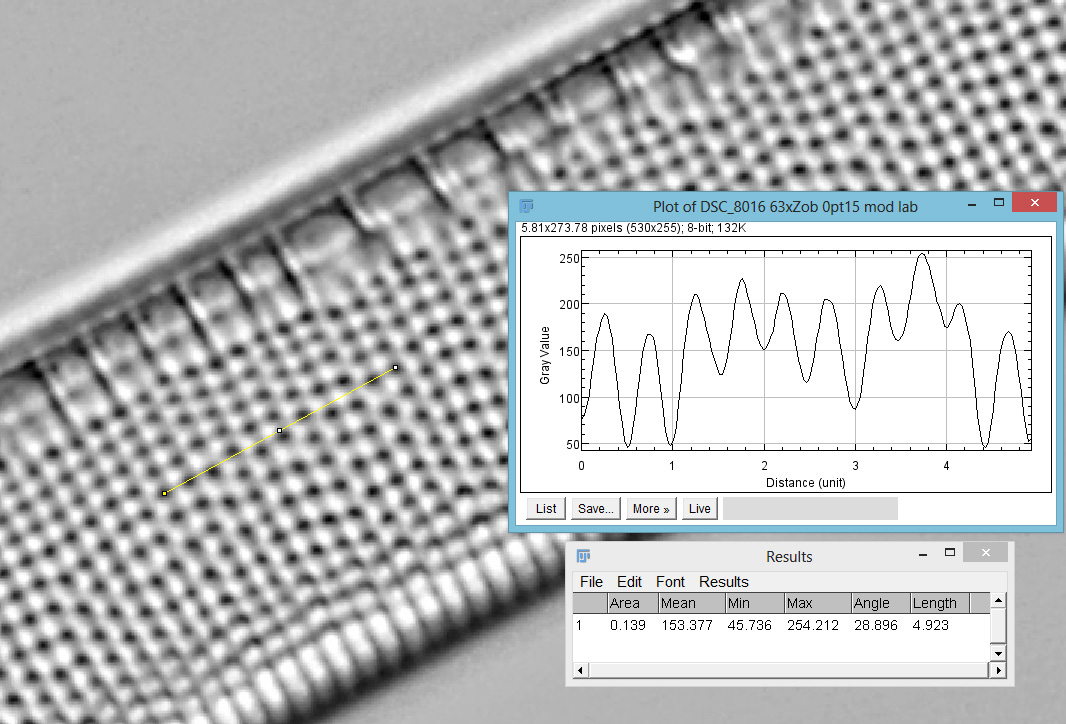
The image below shows a screen grab from ImageJ where I used it to measure the striae spacing (492nm).
492nm striae spacing on Nitzschia sigma
With this objective having the ability to adjust for coverslip thickness, it got me wondering as to whether varying this collar changed the field of view of the image and if so by how much? If this varies significantly it would have a big impact on the size of any scale bar I apply to the image. Do I need a different scale bar for every setting?
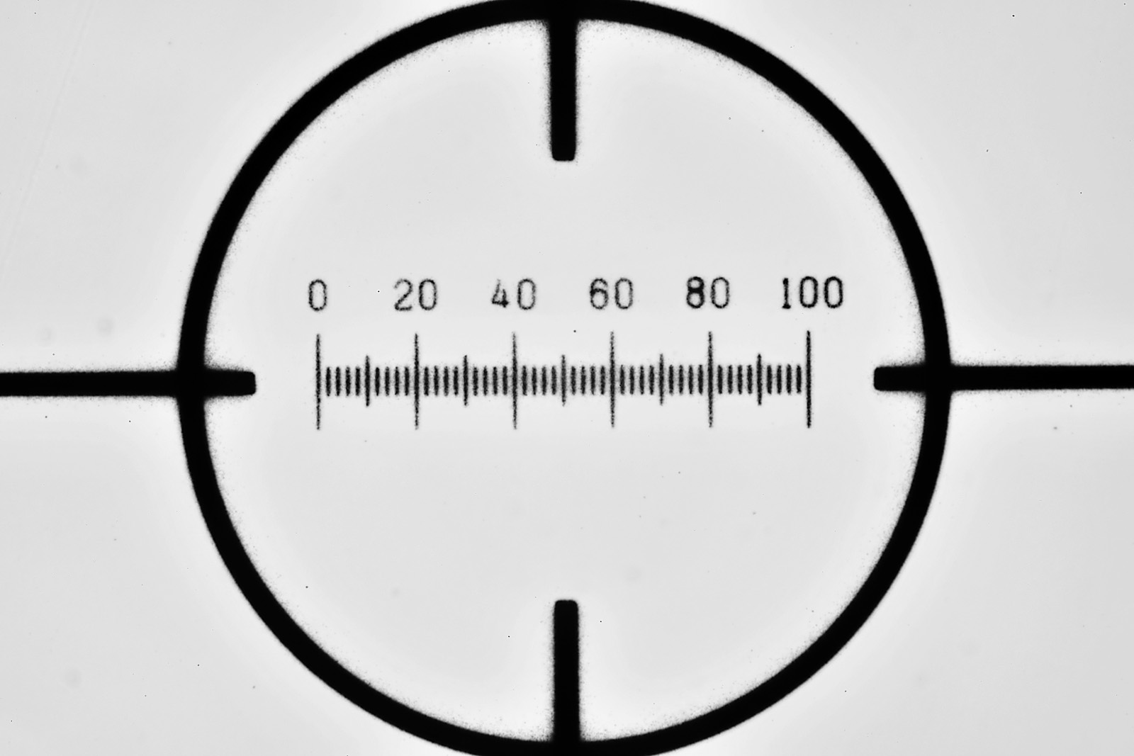
To look at this I did a set of measurements using a Graticules Ltd (now Graticules Optisc Ltd) 100 micron slide. The experiment was a ‘look see’ setting the collar to different positions, and then imaging the slide each time after refocusing. The images were then put into Photoshop and the number of pixels for the 100 micron scale bar measured.
First an image of the 100 micron scale, reduced in resolution for sharing here.
100 micron test slide
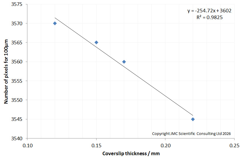
Now the results of the measurements.
Comparison of size of 100 micron test and coverslip thickness setting
There was a change in the size of the 100 micron scale bar for the different settings. It varied from 3570 pixels when set to 0.12mm, to 3545 pixels for the 0.22mm setting. While there is an obvious trend, the change is small, basically less than 1% from one end of the adjustment range to the other. The difference between 0.17mm and 0.15mm was 5 pixels, which was about the limit of how well I could judge it in Photoshop, so I would say is down in the noise. This equates to just over 0.1% over 3500 pixels, so I can be fairly safe in using the same scale bar for my images when the coverslip thickness is 0.15mm or 0.17mm. Does adjusting the collar impact the field of view? Yes. Is it significant? Not enough to make me worry for the imaging I am doing with it, however if set to the extreme ends of the range I would probably correct for it.
Before finishing up though, I will point out some compromises with this experiment. I did not use a coverslip on the stage graticule. I just used water immersion direct on to the slide, and then adjusted to collar to different settings. The images, and measurements were done in Photoshop not ImageJ. I would say 5 pixels was about the limit of what I could judge in Photoshop, but there is a clear trend from one end of the scale to the other, rather than a random scatter, so I can confident in my measurements. Also the microscope is my modified Olympus BHB using a Nikon 2.5x CF PL photoeyepiece. This is a mismatched system. Would I see different results on a Zeiss microscope which this objective was designed for? Maybe. However I can only test on what I have, and I consider this a worst case stress test.
I did this work as searching online for an answer to the question ‘will changing the coverslip correction collar on an objective impact the field of view’ didn’t give me any definitive answers, which I was a bit surprised at. Sometimes, experiments are the only answer…..
As always, thanks for reading, and if you’d like to know more about my work I can be reached here.
A few weeks ago I received a 41mm f2.5 UFAR lens which was developed for the Soviet Mars programme (you can see my initial work on it here). As it was, fitting a filter to the front wasn’t really feasible. A good friend of mine, Dr Klaus Schmitt, who has one of these lenses, showed me the filter ring he’d had made. I thought I could make one based on a step up filter ring, so I have gone ahead and done that. I now have something I can attach filters to, so today I am sharing my first UV photograph with this historically very interesting lens.
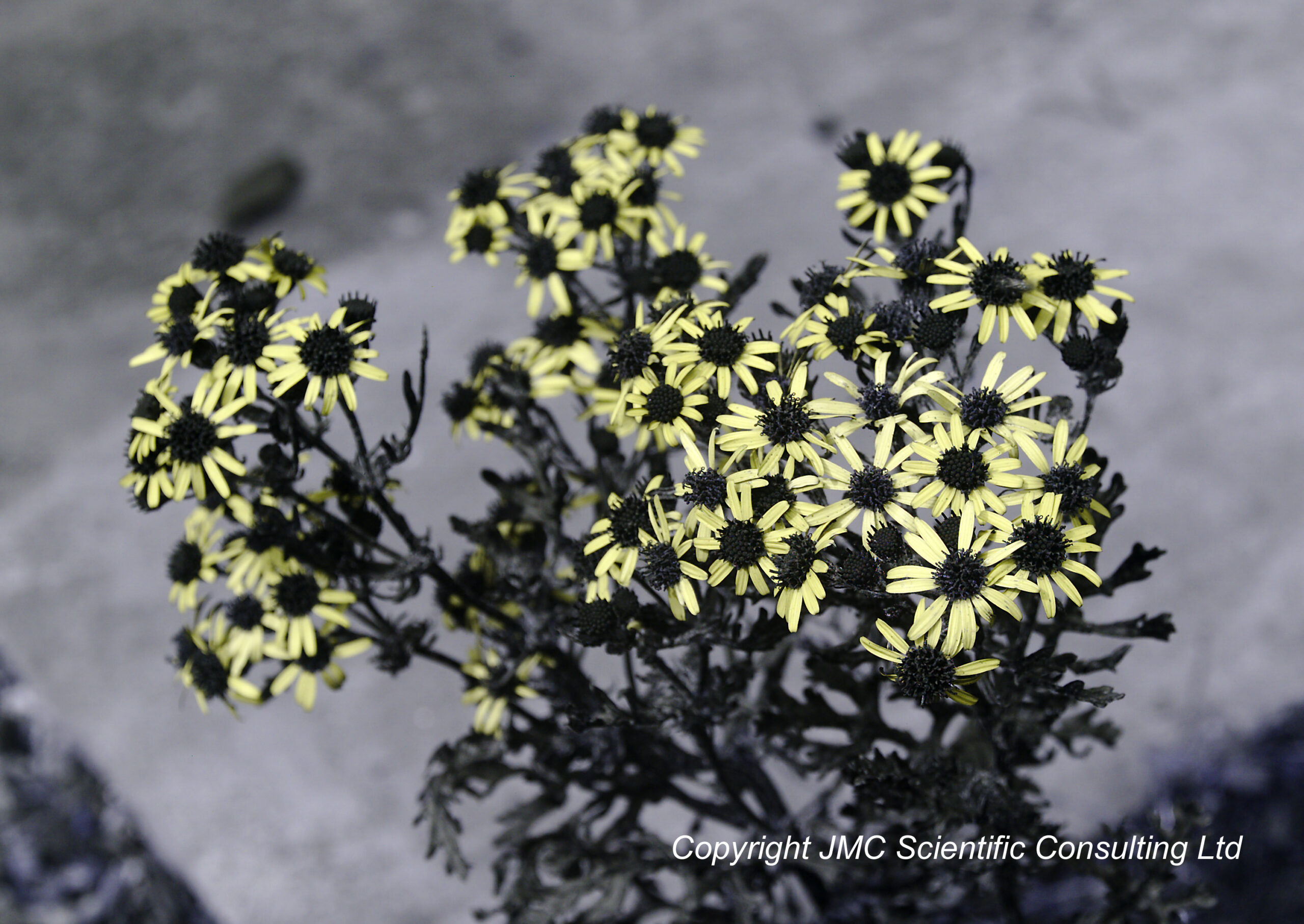
Here’s a UV photograph taken of a Ragwort plant in my garden.
Ragwort photographed in UV light using the 41mm UFAR Mars mission lens
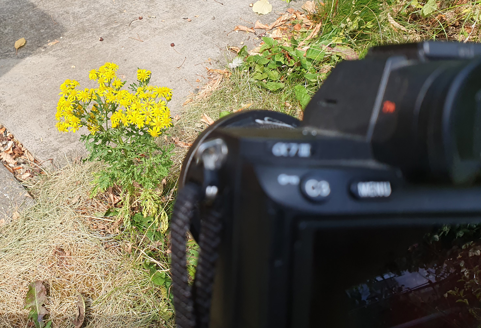
Ragwort flowers are yellow in normal visible light as shown in the camera phone picture below.
Ragwort in normal visible light
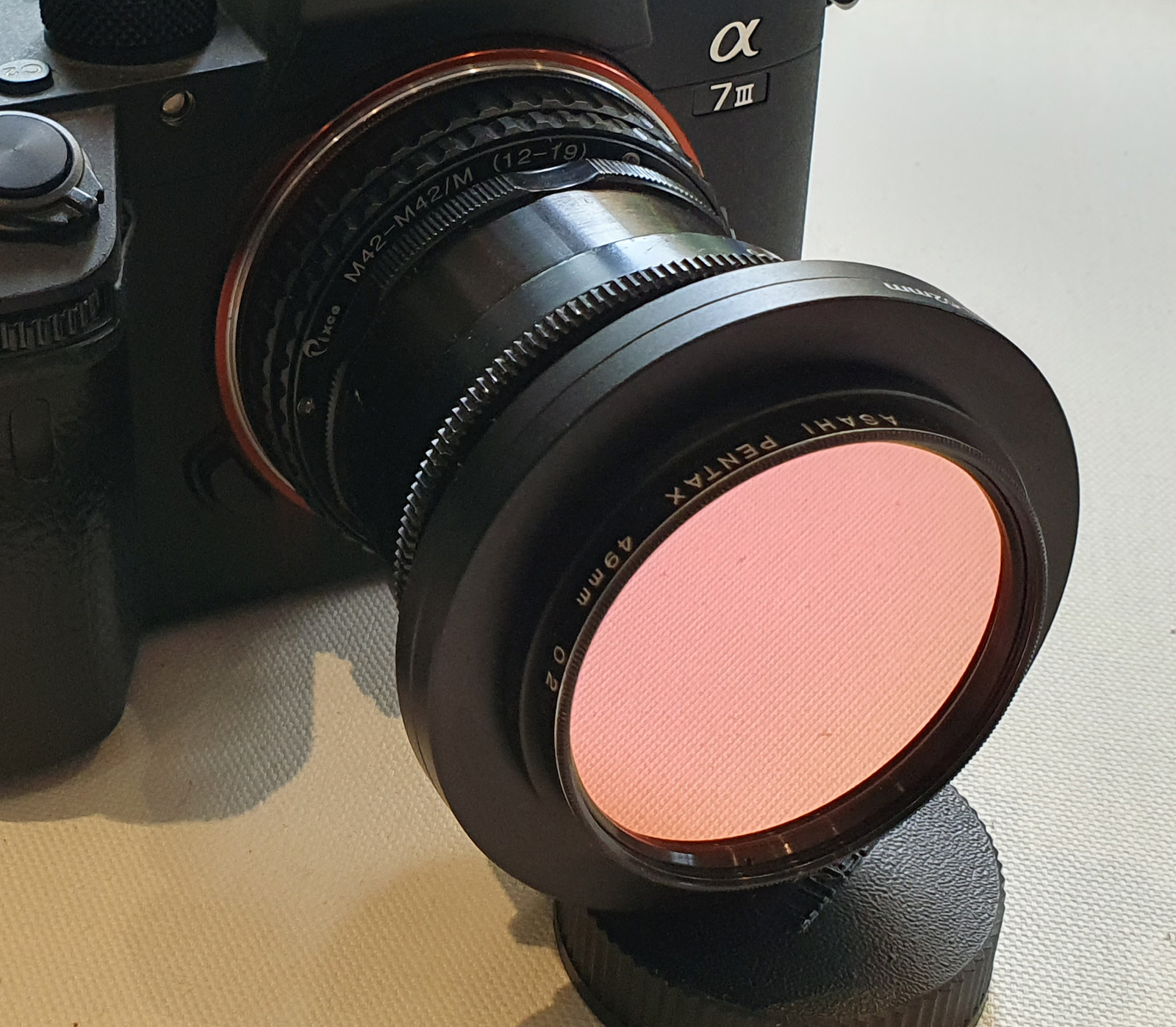
In UV the middle of the Ragwort flowers are strongly UV absorbing, and they show up as black. Some details about how the image was captured. The camera is a multispectral converted Sony A7III (this can be used for UV, visible and IR imaging depending on how the light is filtered). A Sony to M42 thin adapter was used, with a 12-19mm helicoid. The lens was screwed in to the helicoid (at 12mm on the helicoid the lens can just focus to infinity). My filter ring adapter is on the front of the lens, more on this in a minute. Then a Baader Venus U filter in a 49mm filter mount, to remove the visible and IR light and give a UV image. ISO 400, f8 on the lens, and 1.6s exposure in natural daylight. I was amazed to get 1.6s without a breeze to move the flowers. Whitebalance was done in Darktable, using a PTFE disc standard. The image is cropped from the full frame (more on that in a minute). The lens performed very well, especially when stopped down to f8, and it is certainly a UV capable lens. I’ll add a lens hood in future, but for now I just shaded the front of the filter to reduce the chance of flare.
Some details on the filter adapter. I bought a 52mm to 67mm step up ring and removed the central portion, so that it fit on the front of the lens. Four holes were drilled and M2, 0.40 pitch, 4mm long screws were used to attach the adapter using the existing holes that are present on the lens. Then a 67mm step down ring was used to be able to mount the filter.
Front filter adapterBaader Venus U UV filter installed
I’ll leave the filter ring adapter on the front of the lens as it is a convenient place to put a lens cap. The only downside is that the f stops can’t be seen when a filter is installed, so I need to set the aperture and then install the filter.
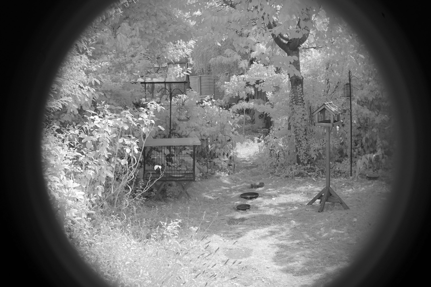
Some more about the lens. The lens does not give full coverage on a 36x24mm sensor as can be seen below. This was focused to about 10m, and done without a filter so is a ‘full spectrum’ image which is dominated by the IR, and has been converted to monochrome.
Coverage of the 41mm UFAR lens (full frame 36x24mm sensor)
Obviously when using in more of a macro mode, the coverage is a bit wider, but nowhere near 36x24mm. Certainly a very usable lens though, especially on a cropped sensor camera.
I hope you enjoyed this little journey into a bit of optical history. My work allows me to use and test some really interesting and unusual equipment, and as a geeky scientist I enjoy sharing these findings with you. If you’d like to know more about my work I can be reached here.
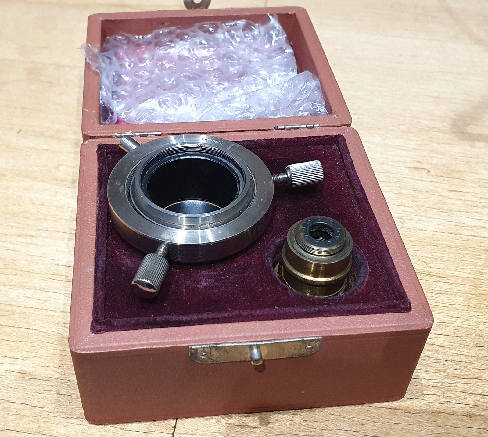
For those of you that don’t follow my work, I like to use historic optics on my microscope and see what they can do. A few weeks ago I got a Leitz darkground condenser made from quartz instead of glass (which I wrote about here) as I wanted to try it for my UV imaging research. The condenser was screwed into a holder, and so far I have been unable to free it off from that (likely it hasn’t been unscrewed in about a 100 years). As I wanted to use this on my microscope the simplest answer would a cylindrical adapter to fill the space between the condenser and the microscope’s condenser holder. A simple enough task for a machinist or someone with a 3D printer, but I am not a machinist, nor do I have a 3D printer. So I approached a UK company – Flex 3D Printing Ltd – with my rough sketch and they were quickly able to print me up a cylindrical adapter. Today I’d like to share some imaging work done with the condenser now that it can be mounted in the microscope.
First a image of a diatom slide (more on the slide in a minute) using a 10x Nikon Plan Apo NA 0.45 objective and 450nm LED light. The Leitz Quartz darkground condenser was oiled to the underside of the slide (glycerin would have been preferable, but oil was fine in this case).
10x Nikon Plan Apo NA 0.45 objective, 450nm light
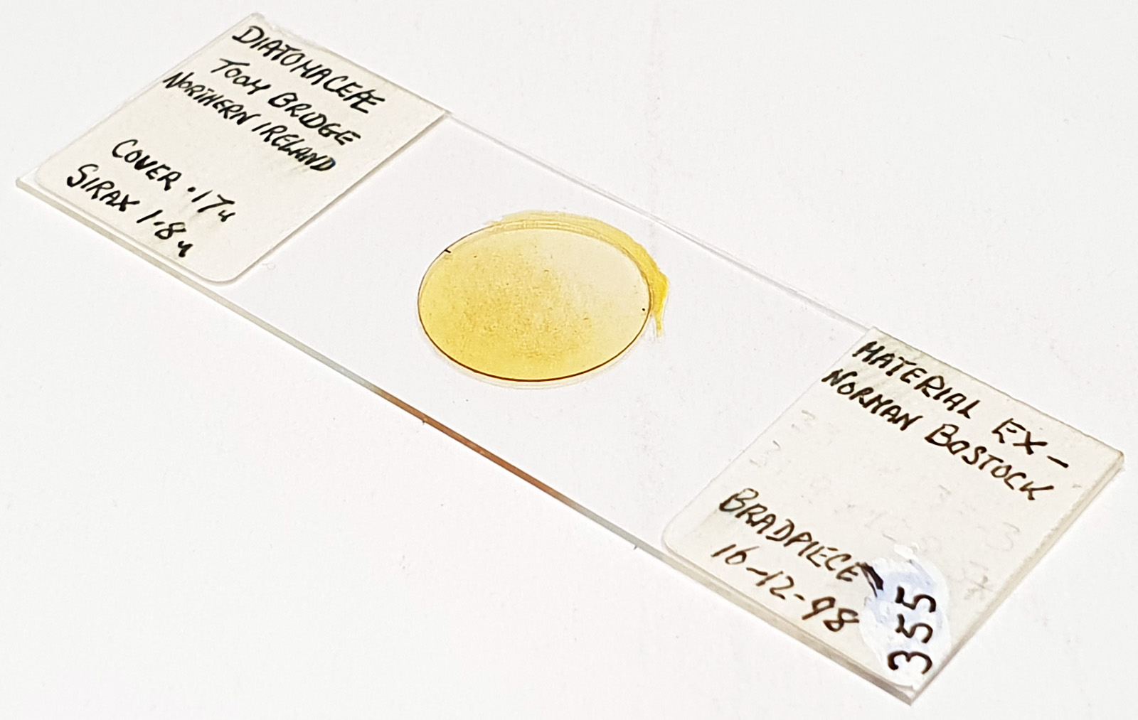
The slide has diatoms from Toome Bridge, Ireland, and shows a good range of species. The long one with rounded ends near the middle of the image is a Pinnularia of some type. This (and the small fragment to the left of it) will be the area I concentrate on for the rest of the images. All the images are single shots, not stacked. Focus was done by eye as a ‘best guess’ using live view on the back of the camera.
Next is an image using a 40x Leitz Pl Apo NA 1.00 oil immersion objective. For this and subsequent images the orientation has been rotated 90 degrees.
40x Leitz Pl Apo NA 1.00 objective, 450nm light
I used 450nm light for this image. Along the centre of the Pinnularia is a raphe line with a small gap in the middle. Perpendicular to this running to the edge of the diatom are striae (these have rounded ends near the middle of the diatom). To the lower right of the main Pinnularia is a fragment of another one. With this objective the striae are easy to see, but the smaller structures within them (called poroids) are not.
Next up in magnification is the 63x Leitz Pl Apo NA 1.4 objective (used with oil immersion). First using 450nm light.
63x Leitz Pl Apo NA 1.4 objective, 450nm light
And then using 365nm UV light.
63x Leitz Pl Apo NA 1.4 objective, 365nm light
Both images with the 63x objective do not look like darkground images with the black backgrounds. The NA of the objective is now higher than that of the condenser (which is about 1.2) so a true darkground image isn’t made. This type of image is more ‘circular oblique’ lighting, with the light coming in from all around but at a steep angle.
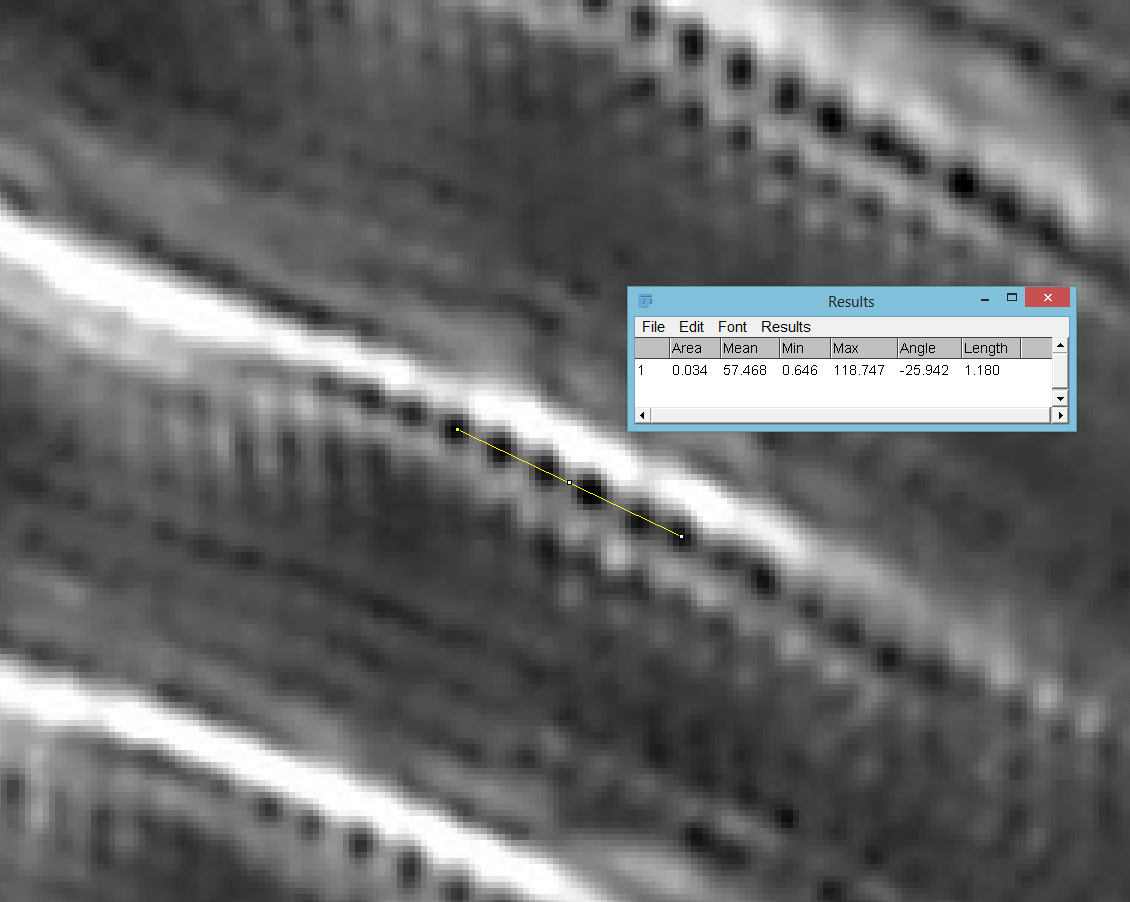
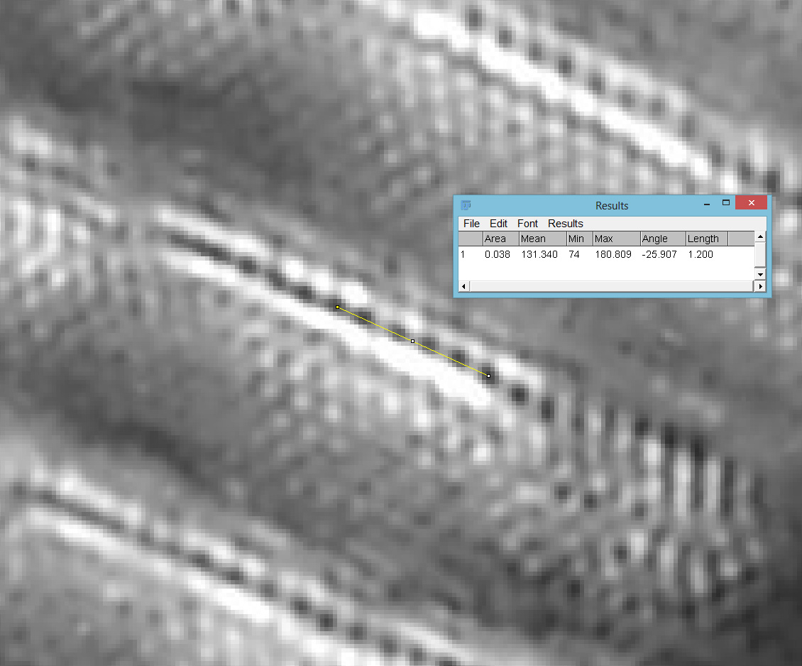
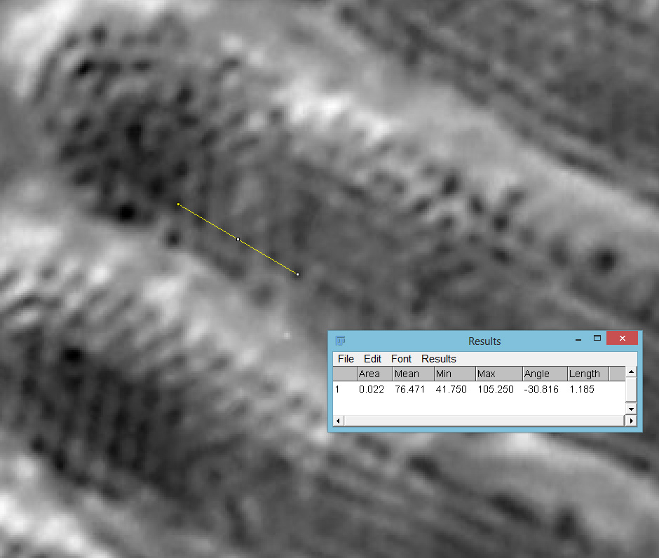
Going in close on part of the image (actually part of the fragment to the lower right), it was now possible to see the poroids within the striae of the Pinnularia and to measure the spacing between them. Below are two screen grabs from ImageJ. First from the 450nm image.
63x Leitz, 450nm, 236nm poroid spacing
Then with using 365nm UV light.
63x Leitz, 365nm, 240nm poroid spacing
The poroid spacing (centre to centre) was measured as 236nm on the image with 450nm light and 240nm when using 365nm light. Moving from 450nm to 365nm illumination changes the focal position (and therefore magnification) of the objective, so I have to account for that. Given that the measurements of the poroid spacings were only just over 1% different this is within acceptable errors. Resolving poroids on Pinnularia using optical microscopy is a real challenge, so it was great to see this. These features are less than a quarter of a micron apart. A quarter of a micron is the size of a small bacterium, or less than 1/200th the diameter of a human hair.
The 365nm image should be better resolution than the 450nm one (shorter wavelength better resolution). Given my manual focusing I can’t be sure I am actually seeing that, however in the full size images it seems to show better contrast if nothing else.
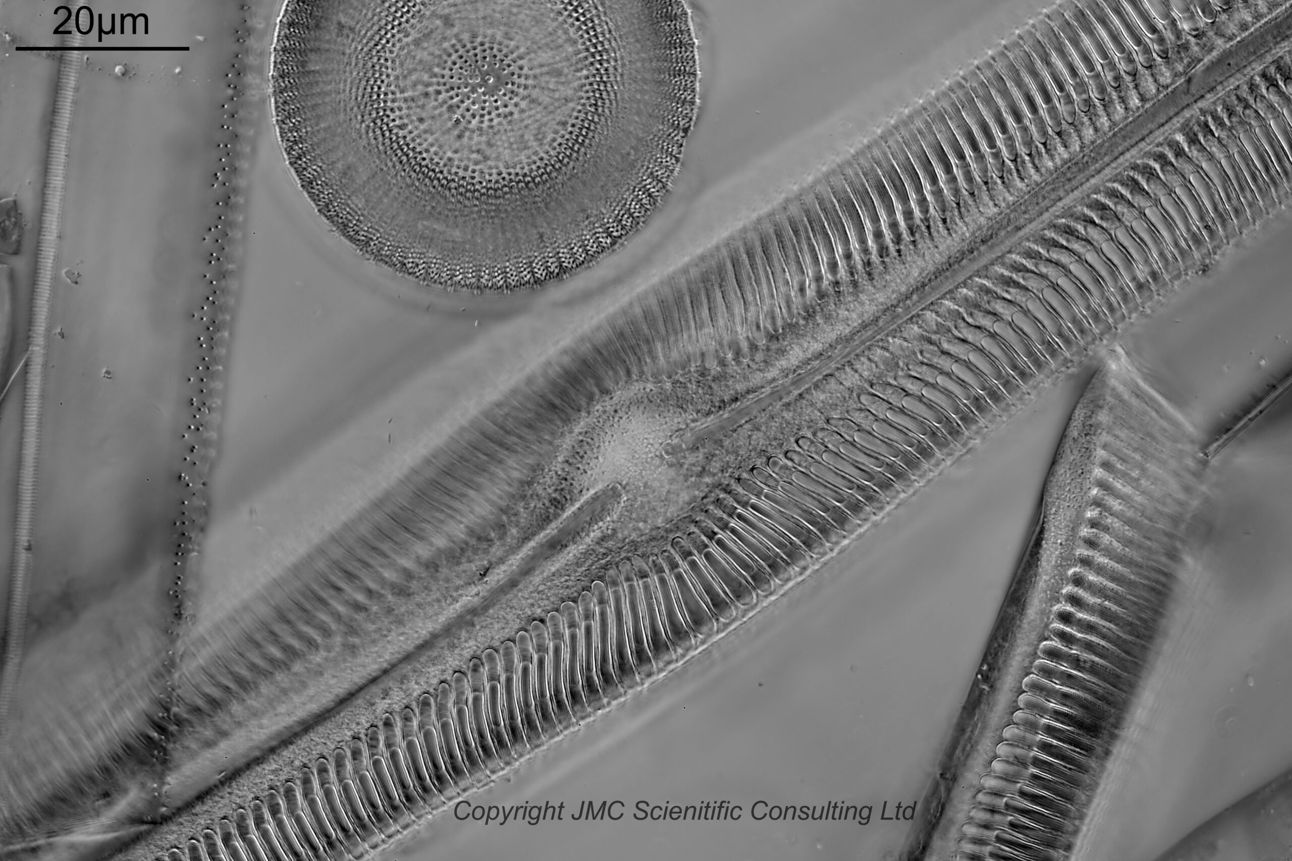
I did have another objective to try, a Leitz 100x Pl Apo NA 1.32-0.60 with an adjustable iris. Two images were done with this, one with the iris fully open and the others with the iris closed down just enough to make the image darkground. Both were done with 450nm light. First with the iris fully open.
100x Leitz Pl Apo NA 1.32-0.60 objective, iris fully open, 450nm light
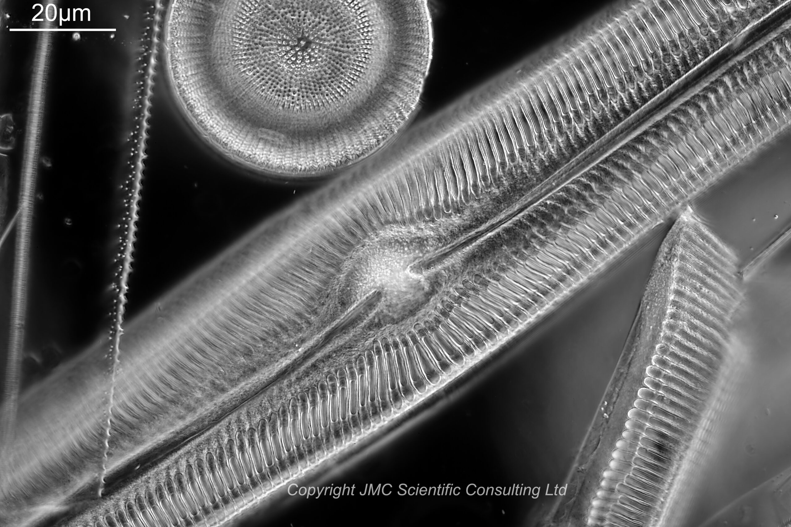
Next with the iris closed down enough to make the image darkground.
100x Leitz Pl Apo NA 1.32-0.60 objective, iris slightly closed, 450nm light
Closing the iris reduces the NA of the objective, and as it goes below that of the condenser, the image goes from ‘circular oblique’ lighting to darkground.
I also did a screen shot of the Pinnularia fragment (although a slightly different part of it this time – focusing on the live view of the camera is not always ideal). This was done with the iris fully open.
With the iris fully open and with 450nm light, the poroids were visible (and measured spacing was 237nm with this objective), but with a slightly softer image than the 63x objective. This would be expected, as although the 100x objective offers more magnification, it’s NA when the iris is wide open is lower than that of the 63x (1.32 vs 1.40). However given the higher magnification, there are more pixels to play with and the image is smoother. I am not showing a magnification of the image with the iris closed down. Although the image was darkground, closing the iris reduced the resolution and the poroids were not longer visible. Swings and roundabouts……
So, overall the condenser performed well and allowed imaging of poroids in a Pinnularia diatom with spacings of around 250nm, and allowed the use of UV light (365nm) as well as visible light.
Before I wrap this up, some info about the slide and the adapter. The slide was by Neville Bradpiece, and is a strew from Toome Bridge, Northern Ireland. The diatoms are mounted in Sirax which is a high refractive index mountant.
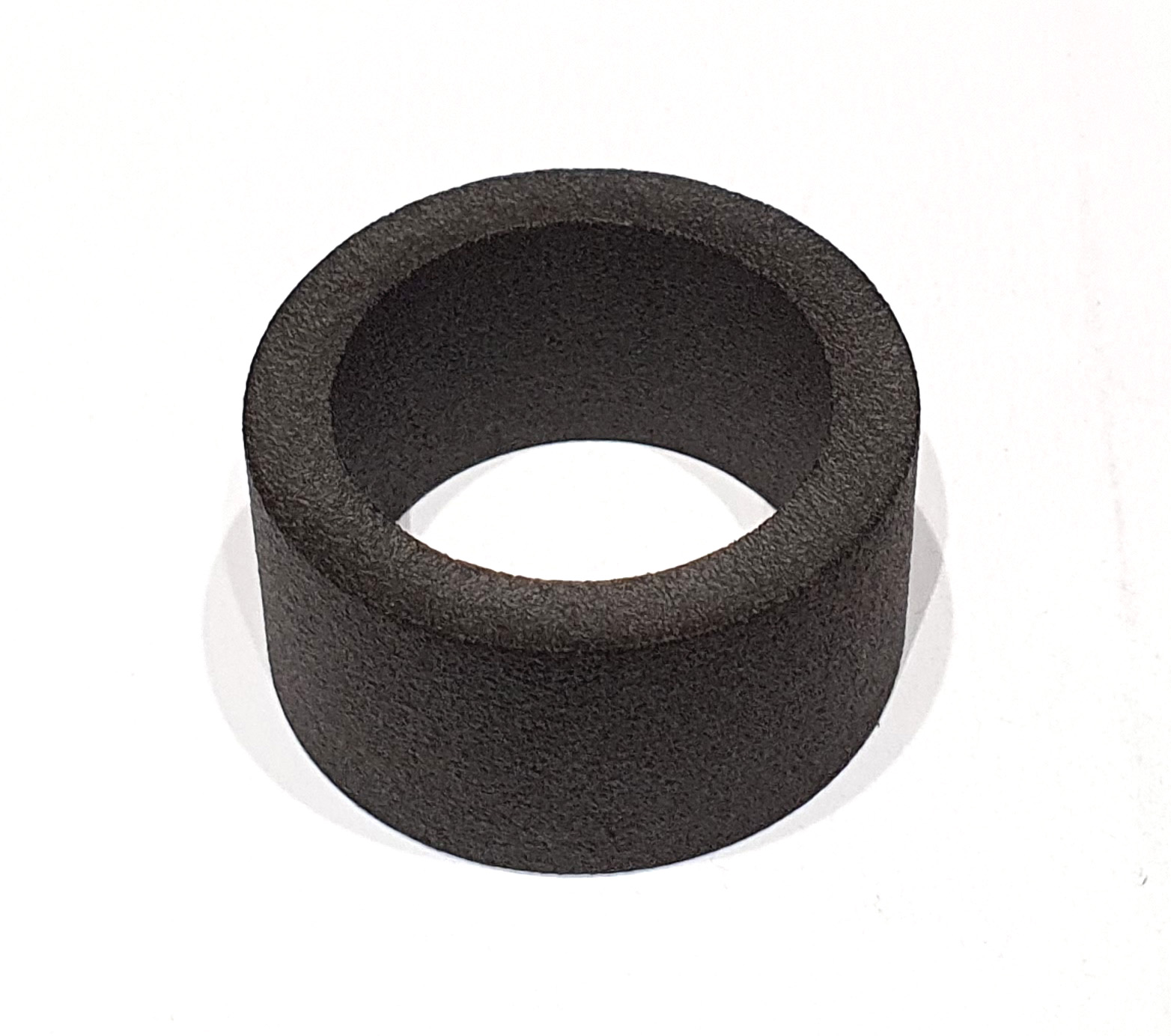
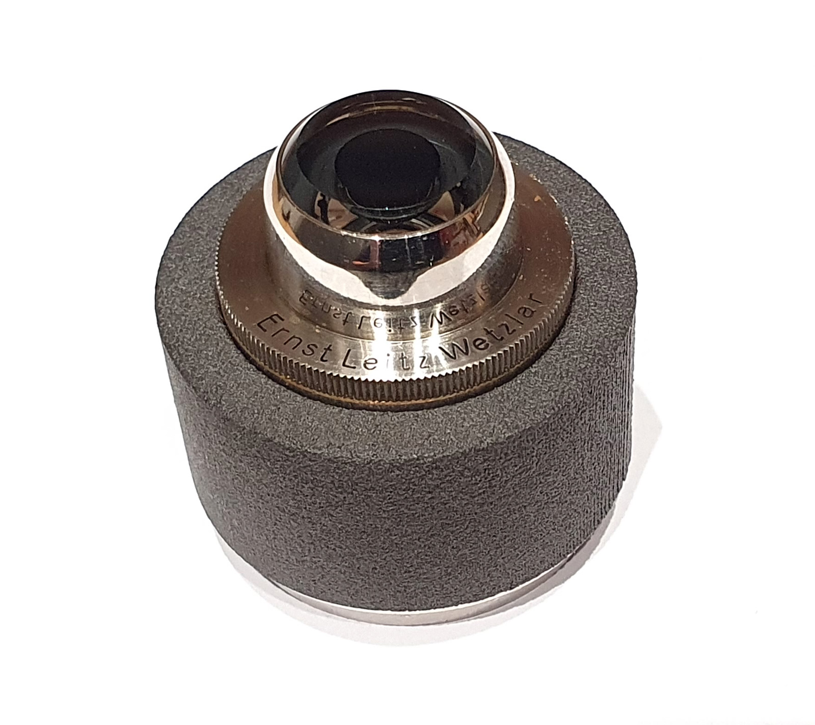
The adapter was made from PA12 Nylon. The images below show it by itself and mounted on the condenser.
PA12 Nylon adapter from Flex 3D Printing LtdPA12 Nylon adapter and Leitz Quartz darkground condenser
The condenser was a friction fit on the inside, although in future I will add a little double sided tape for extra security (I do not want the condenser falling out the bottom of the adapter and crashing into the field lens on the microscope, especially when that is a fused silica one).
Big shout out to Flex 3D Printing Ltd. I’m always happy to support UK businesses and without folks like these my work would be a lot more difficult.
As always, thanks for reading, and if you’d like to know more about my work I can be reached here.
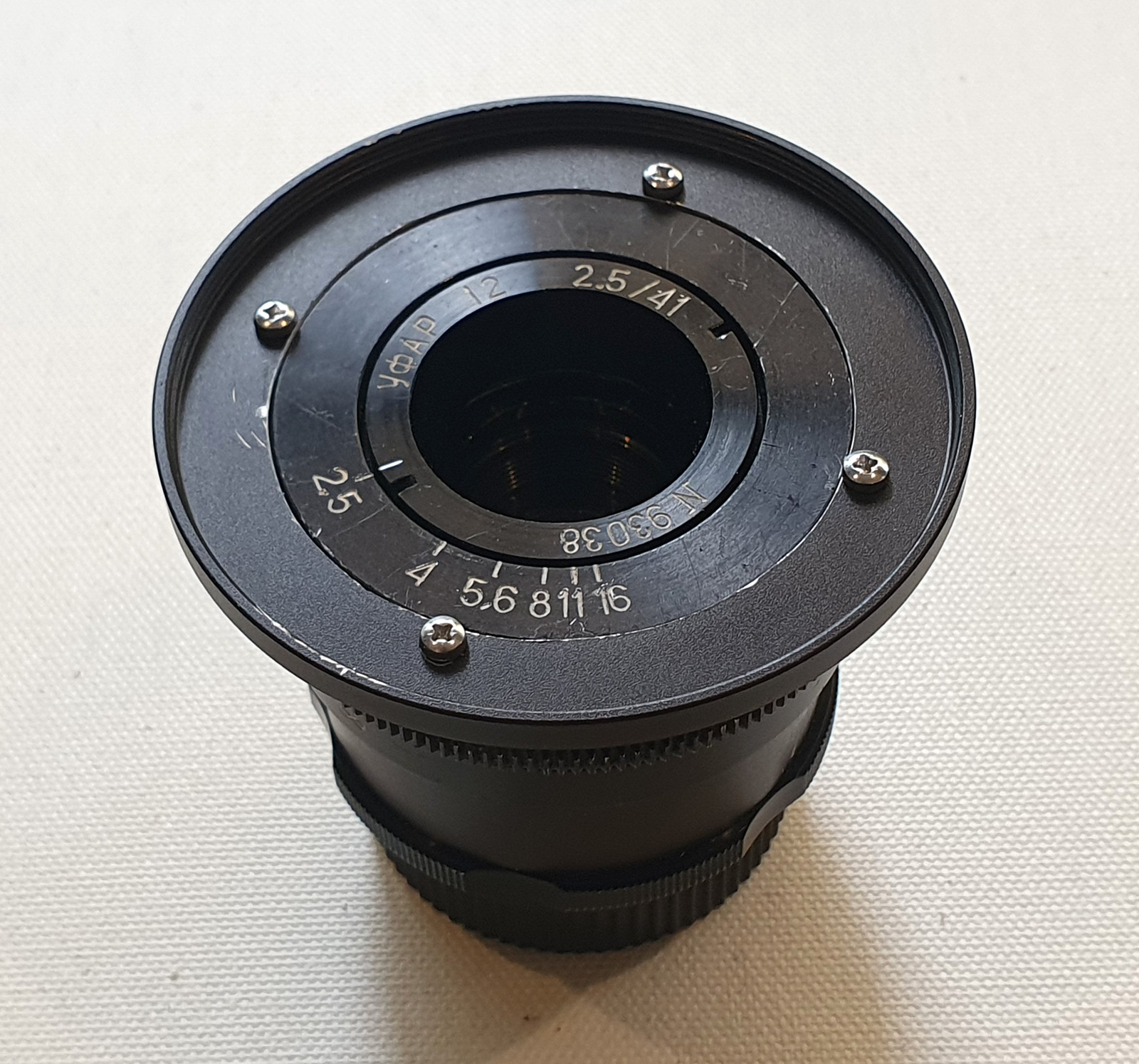
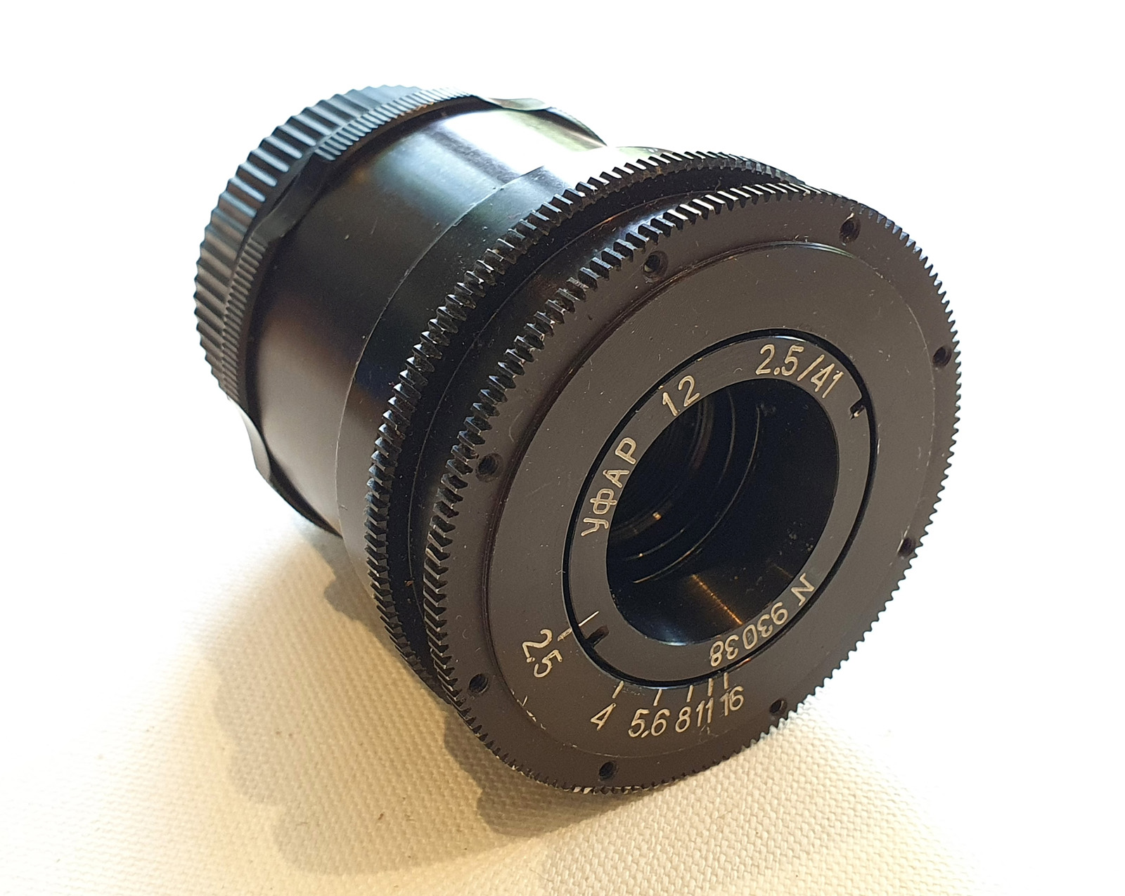
Every now and then I’m lucky enough to get an unusual piece of imaging history. This one certainly falls into the ‘unusual’ category. It’s a 41mm f2.5 Ufar lens that was developed for a Soviet Mars mission in the 1990s.
Ufar 41mm f2.5 lens
With this one there are now 7 known to exist. And no it hasn’t been to Mars and back, but it was developed with a journey to Mars in mind.
It’s quite small and compact and with an iris that goes from f2.5 down to f16. The mounting is M42 thread, but not the usual flange to focal plane distance for M42 (FFD is 30.36mm vs 45.46mm for normal M42), so using it on a mirrorless camera (or rangefinder) is the best bet, unless you want extreme macro.
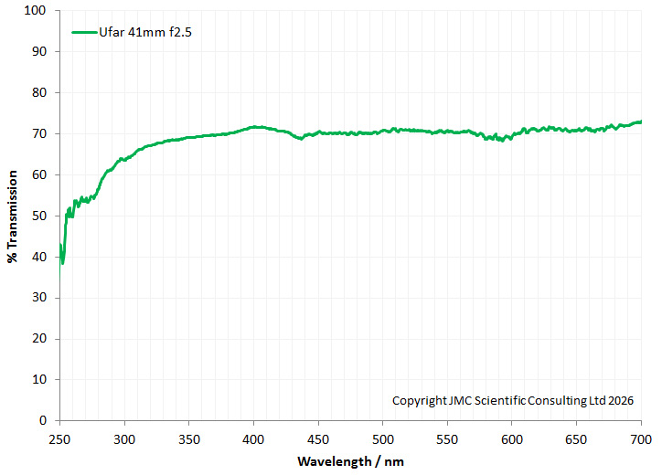
It does not have glass lens elements (it’s quartz and calcium fluoride) as it was designed for UV work as well as longer wavelengths. This can be seen when you look at the transmission spectra which shows good transmission down to 300nm and below where normal glass would just block the light.
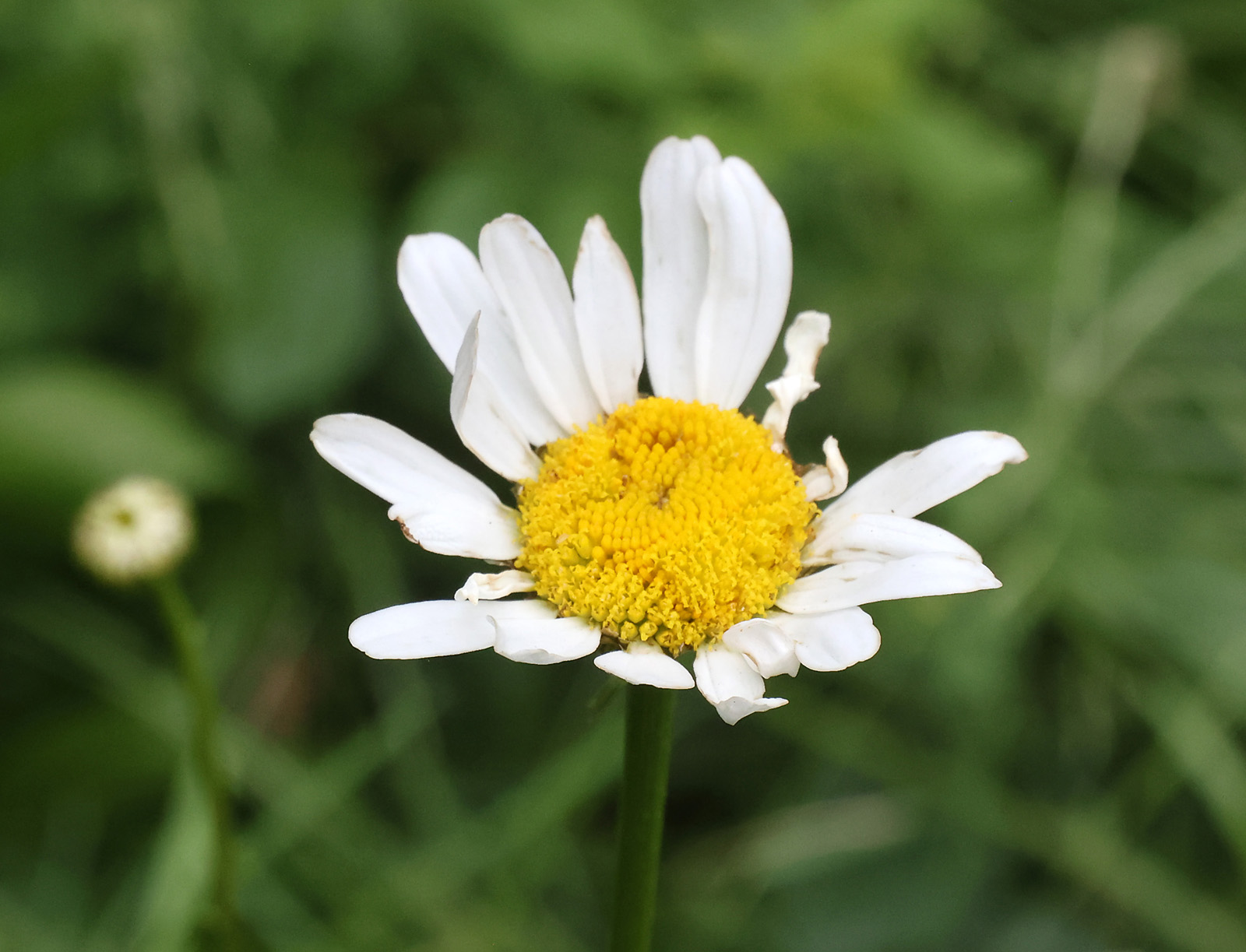
A quick snap from the garden (in visible light) with it on a normal Canon Eos R7 camera.
The lens does not cover 36x24mm format however I plan to do more work looking at the lens performance (including coverage) in the future. Next step will be to make a filter mount to put a UV transmission filter on the front.
As always thanks for reading, and if you’d like to know more about my work I can be reached here.
Today’s post is one about the dangers of making assumptions in science…..
For background, I built a UV transmission microscope a couple of years ago. This was done for a couple of reasons; to see if I could, to use some quirky and unusual technology and equipment, and to be able to image different sunscreen components in a formulation at both long and short UV wavelengths. A UV transmission microscope capable of working down to 300nm and below is a challenge as normal glass will just absorb the light at those wavelengths. As such it becomes necessary to manipulate the light with materials such as quartz and calcium fluoride and/or mirrors, rather than using glass.
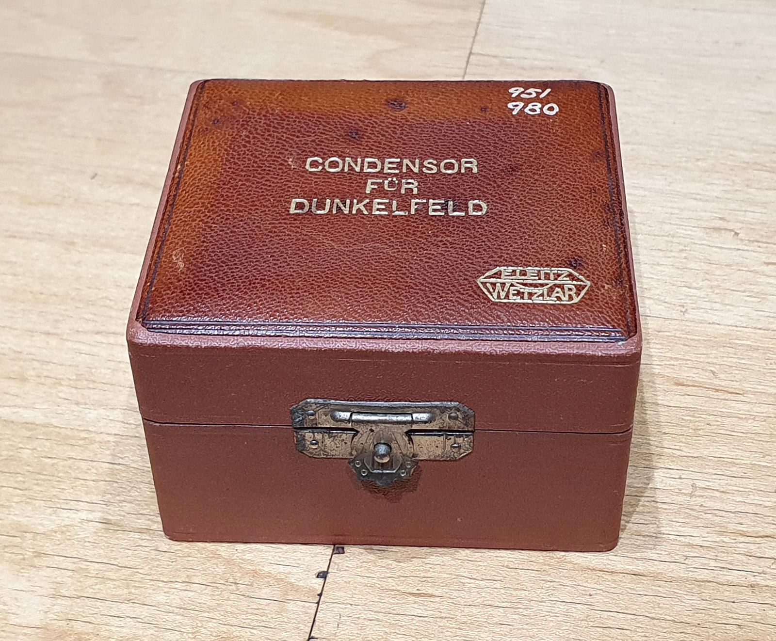
Over time since then I have built up quite a collection of UV capable lenses such as Zeiss Ultrafluars, and Leitz UV objectives. I have a couple of condensers which I can use such as a Zeiss Quartz one. However what I don’t have is a darkground condenser which I can use in the deep UV. There have been a few made over the years, including a lovely Watson quartz cassegrain which I was fortunate enough to borrow for a while (more on that in a minute). In an old Leitz Darkground Condenser brochure they mentioned that their condensers could be requested in UV crown glass or quartz (for extra cost), but until recently I had only ever seen one Leitz darkground condenser with a ‘Q’ on it, and that was just a photo. These are rare beasts. A few weeks ago, much to my surprise, a Leitz darkground condenser with ‘Quarz’ engraved on it came up for sale on ebay, so I quickly bought it.
My assumption with this was that being quartz it would be able to transmit the light down to 300nm and below, and I could use it for deep UV darkground imaging. As we shall see, things don’t always work out as planned……
First though, some pictures of the condenser.
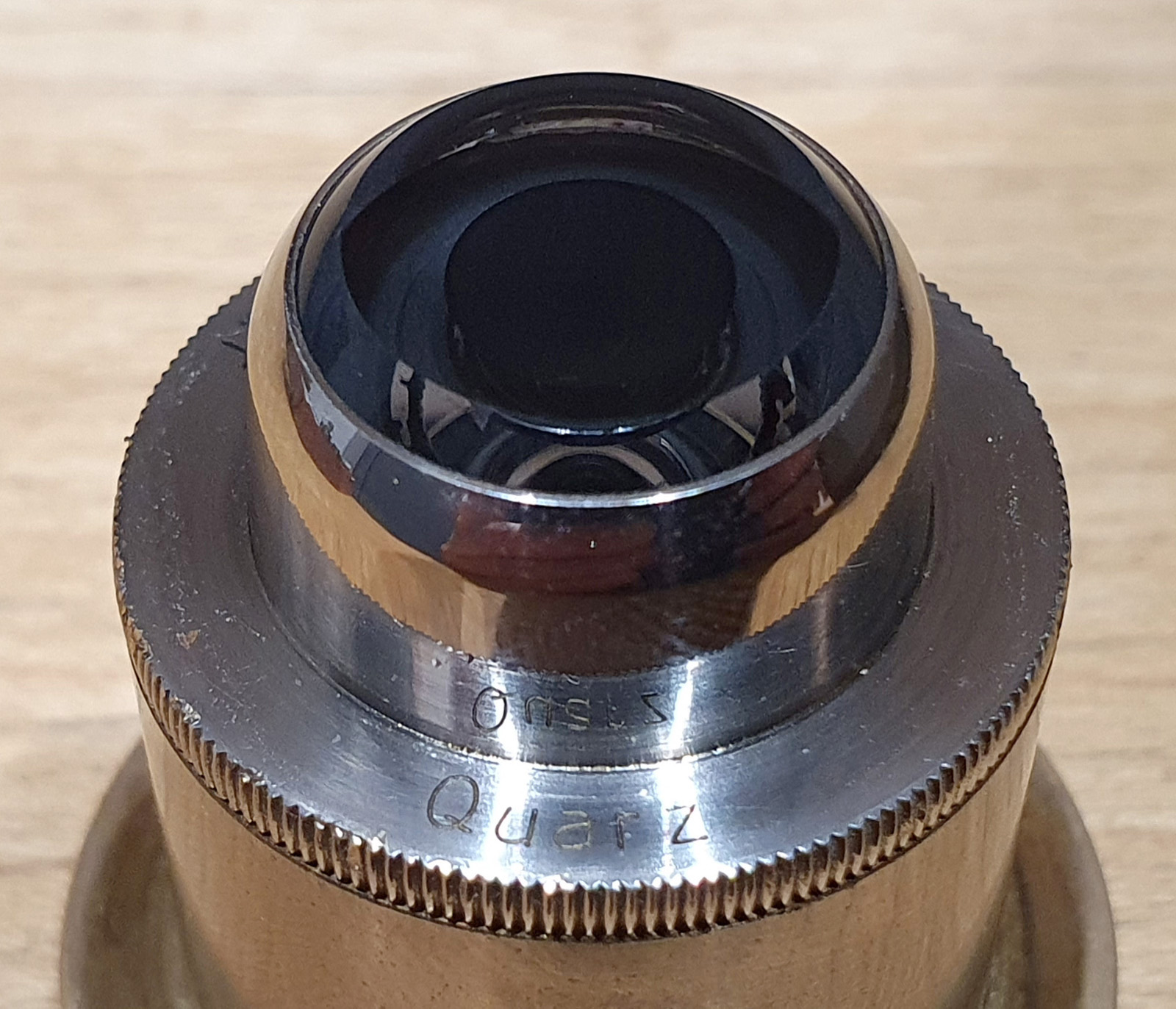
All in all, it is in pretty good condition (given it is probably around 100 years old). There are a couple of very minor scratches on the front face, but they are not near the middle, and shouldn’t really impact its usability. As can be seen in the top image, it has ‘Quarz’ (the German spelling of Quartz) engraved on it.
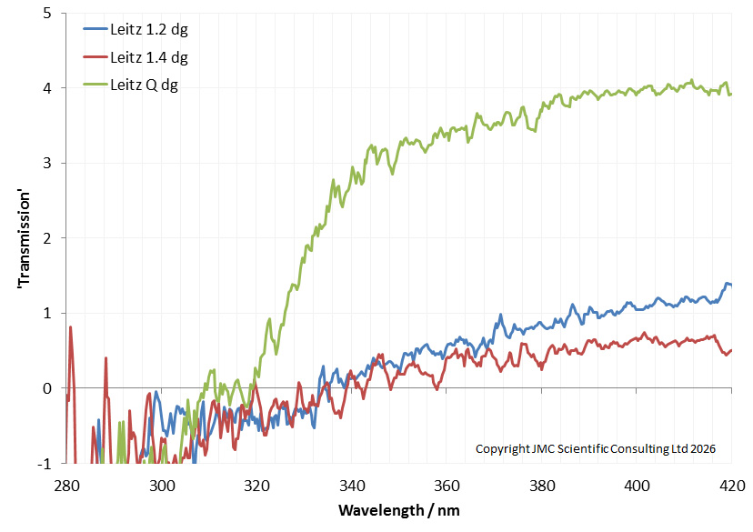
First thing was to try and measure the transmission through it. While I have got a device to measure transmission through lenses down to about 300nm, with darkground condensers this is a bit of a challenge, as absolute transmission is very low. Down at 300nm, with low transmission, and low sensitivity from the spectrometer at that wavelength, this was going to be a challenge. However I gave it a shot, and got the following.
This ‘thing’ which I have labelled as Transmission vs Wavelength shows 3 Leitz darkground condensers. Two (the 1.2 and 1.4) are standard glass ones, and the Q one is the quartz one. It’s a terrible graph as transmission drops down below zero at the shorter wavelengths, which makes no sense. I am putting this down to low sensitivity of the spectrometer, and low light levels basically making it ‘noise’, as well as perhaps not optimal setup for the experiment. However there does look to be something going on with the data. The quartz condenser shows relatively good transmission down to about 340nm, but after that it drops really quickly, down to the same ‘noisy’ level as the glass ones about 320nm. This is strange as the quartz should be showing good transmission down below 300nm and even 250nm.
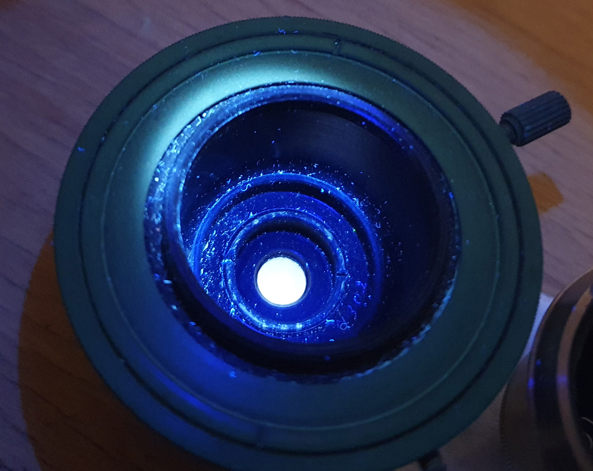
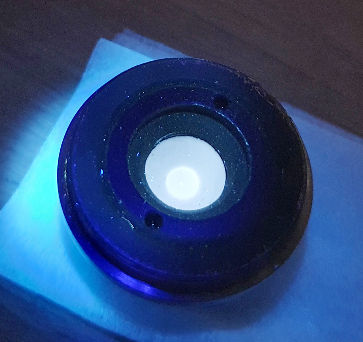
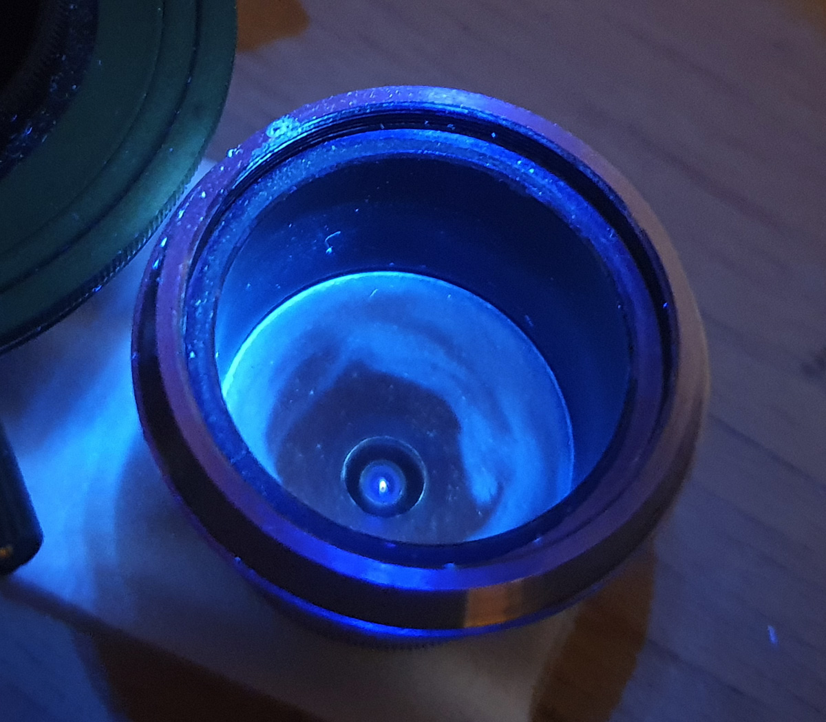
This got me wondering, is the Quarz condenser really just quartz? Is it a ‘fake’? One simple test, is to shine a short wavelength UV torch on to it, and look for fluorescence. A glass one will fluoresce and a quartz one should not. For this I used a 273.7nm torch I have as it has good blocking of out of band light from the filter on the front of it. Here are 3 images showing what the Leitz darkground condensers look like when illuminated with the 273.7nm torch.
Leitz NA 1.2 dg condenser fluorescenceLeitz NA 1.4 dg condenser fluorescenceLeitz Quartz dg condenser under 273.7nm UV light
The NA 1.2 and 1.4 condensers (the first 2 images) which are made from glass fluoresce quite strongly under UV illumination. The glass in them has a foggy ‘glow’ to it. However the quartz one did not fluoresce (there is no glow from the quartz in the image under UV illumination). Phew, at least the ‘Quarz’ condenser looked to actually be Quartz.
This did not explain the unexpected transmission behavior though. Why did transmission look to drop below about 340-330nm?
This was where I started thinking about the mirror. The metal silver has some unusual properties in the UV, in that reflection from its surface drops quite abruptly in the 330-340nm region. It is a well known phenomenon, and I’ve demonstrated it before with some UV photographs of silver foil in the UV region (see here). How were mirrors typically made in the past – silvering….. So the mirrored surface in the darkground condenser is likely silver. Doh. This explains why the measured transmission through the quartz darkground condenser looked to drop below about 340nm. It’s not an issue with the quartz, but with the silver of the mirrors present which are not reflecting the deeper UV light very well. This is a bit of a blow as I had hoped to use this condenser for some deeper UV darkground imaging, but that looks to now not be possible. One lives and learns, especially when it comes to making assumptions in science…..
There was however still the interesting observation from the transmission work where it looked like the Leitz Quartz darkground condenser was letting more light through than the glass ones in the upper UV region. This would be expected – quartz will not block the UV, however glass will to some extent. There is quite a thickness of glass in a darkground condenser, so I would expect this to add up quickly.
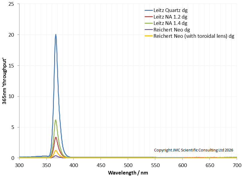
To have a better look at behavior of the condensers in the mid-upper UV, I looked at the transmission again, but using a 365nm torch, and placing it directly behind the condenser. I am calling this the ‘throughput’ of light at 365nm.
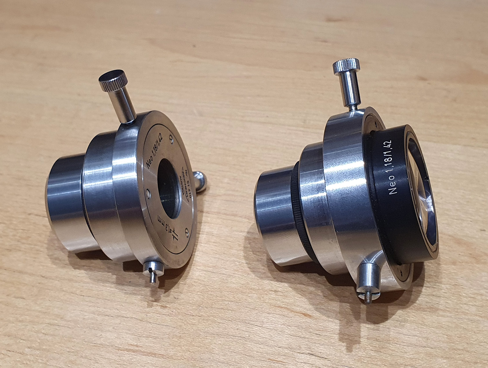
There are some quirks with the data above – not all the condensers where the same diameter at the rear (and all were smaller than the torch diameter). However the Leitz ones were all similar, so they should be reasonably comparable. The Leitz Quartz one does let through a lot more UV at 365nm than the NA 1.2 and 1.4 ones. This is significantly more, and would make the Quartz condenser great for 365nm UV work. In this test I also included a couple of Reichert Neo darkground condensers as I had read somewhere that these were good for 365nm work. One was a bare condenser, and the other has a toroidal lens on the rear which takes the incoming light and focuses it into a ring to make the darkground condenser more efficient. These two Reichert condensers are shown below, normal one on the left, and the one with the toroidal lens on the right.
However I was surprised to find that the Reicherts let relatively little UV at 365nm through. The toroidal lens did improve this quite substantially, but there was still less light than the Leitz glass ones. So I guess I wont be using the Reichert much for 365nm work in the future then.
This was a bit of a roller coaster of a piece of work. I had assumed that because quartz based condensers work in the deep UV, that a quartz darkground condenser would also be good for the deep UV. However it looks like this is not the case, and it is not the quartz but the silver used to make the mirrors which is the issue. Am I disappointed? Yes, a bit, both in myself for making assumptions, and the results. However the Leitz Quartz darkground condenser does look to be potentially very good for 365nm work, so I will have an adapter made up to use it on my microscope. I also found out about the Reichert condenser, so will do some further checks with that on the microscope and see what is going on there.
Near the beginning of this page I mentioned about a Watson Quartz cassegrain dark ground condenser that I had borrowed in the past (some info on that here, and I wrote an article on it for the Journal of Quekett Microscopical Club). However with that lens I never tested it below 365nm, so I do not know if it would behave the same way as the Leitz Quartz one here. If it has silver based mirrors I suspect it would, but that would need testing in the future.
Thanks for reading, and if you’d like to know more about my work I can be reached here.
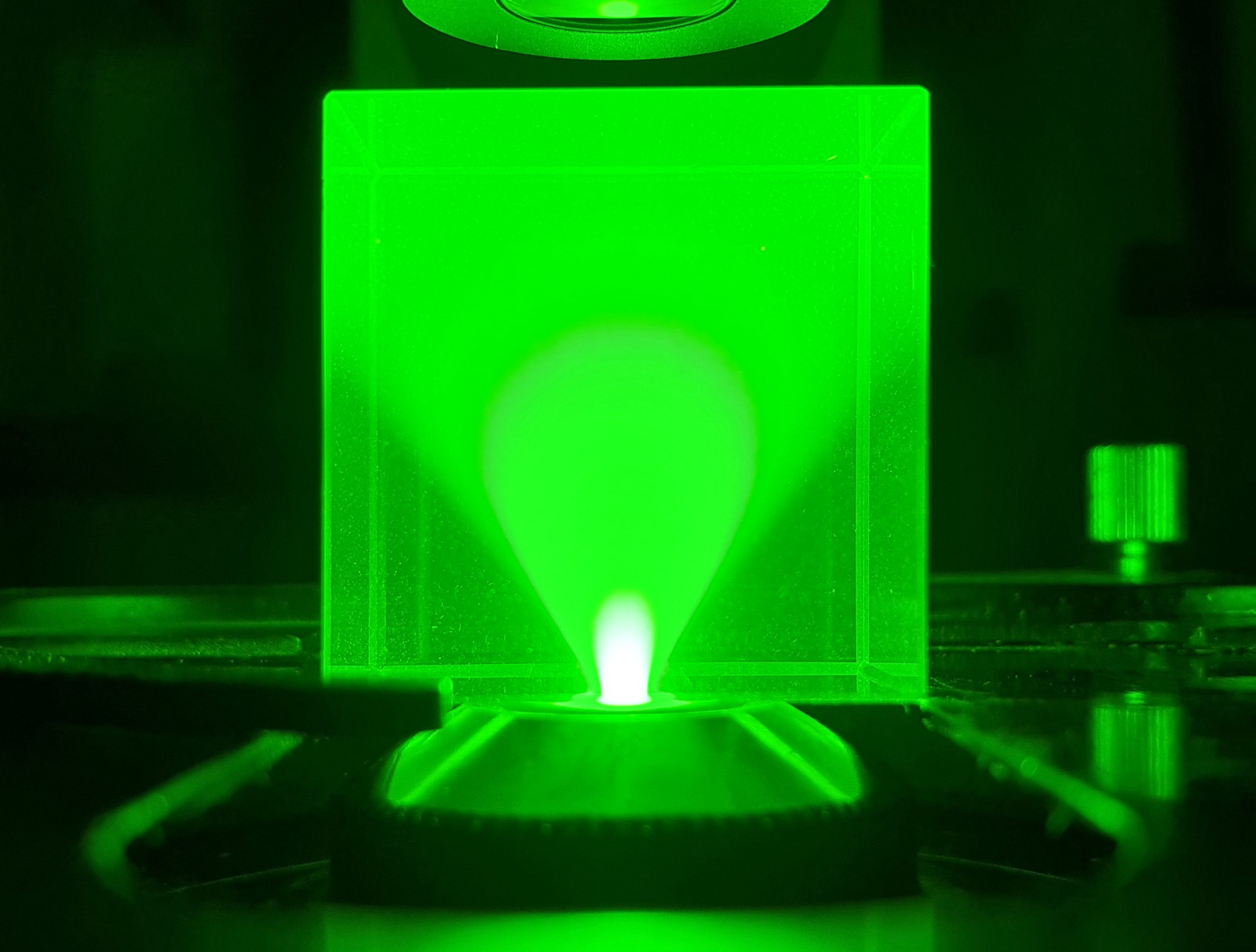
What feels like a long time ago, all the way back in 2020, when I first started my microscope journey, I made myself a condenser using UV fused silica instead of glass. This was so I could use it for ultraviolet microscopy (you can see the early post here). I always wondered how well it worked compared to, for example, the standard commercial Olympus Abbe condenser. Recently I found a way of visualizing the light cone produced by a condenser, and that is by using a uranium glass cube which fluoresces when exposed to UV. Today I want to share the results of a quick test with you, looking at how these condensers behave.
First, and image made with the standard Olympus Abbe condenser, with its iris fully open.
Standard Olympus Abbe condenser, fully open
The condenser is at the bottom of the image, and the light (from a 365nm UV torch) is coming through and hitting the uranium glass cube. The glass fluoresces where the UV hits it. The condenser is producing a nice light cone, with just under a 90 degree spread which is what would be expected in this setup.
Next we have the UV fused silica condenser I made.
UV fused silica condenser, fully open
With my home made condenser, the edge of the cone is a bit less well defined than the one by Olympus, and I think the angle is slightly narrower. I am not hugely shocked that it doesn’t match the behavior of the commercially made one. Also, I had to move the condenser down slightly so the top of it was about 2mm below the glass cube, in order to get the brightest spot at the base of the cube. Again, this makes sense – I used a half ball lens as the top lens of the condenser, while the original was more of a ‘three quarter’ ball. As such mine would be expected to focus higher above the flat part of the lens. Unfortunately getting custom ball lenses ground would not be cost effective for me to consider. For what it is though, and for what it cost me, I am more than happy with its performance.
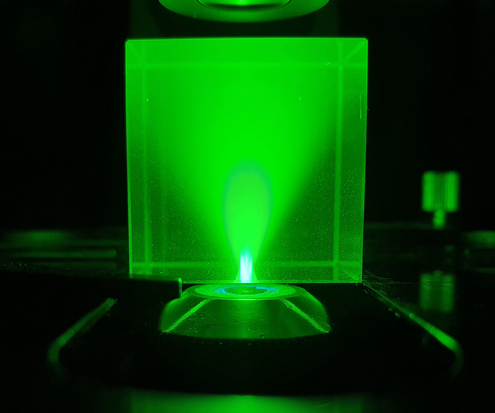
As a final thing, I want to show what happens to the light cone as the condenser iris is closed down (this was the commercially Olympus Abbe condenser).
Standard Olympus Abbe condenser, iris being closed down
Closing down the iris reduces the angle of the light cone, as expected, but it is nice to see this being demonstrated in practice.
Thanks for reading, and if you’d like to know more about my work, I can be reached here.
This post is a bit of a double whammy. First, I’ll share some diatom images from a microscope slide with a very unusual mountant – mercury iodide. Second, I’ll talk about the useful and multifunctional objective I used to take these images – a Zeiss 40x Plan Apo, with an iris and a phase contrast ring.
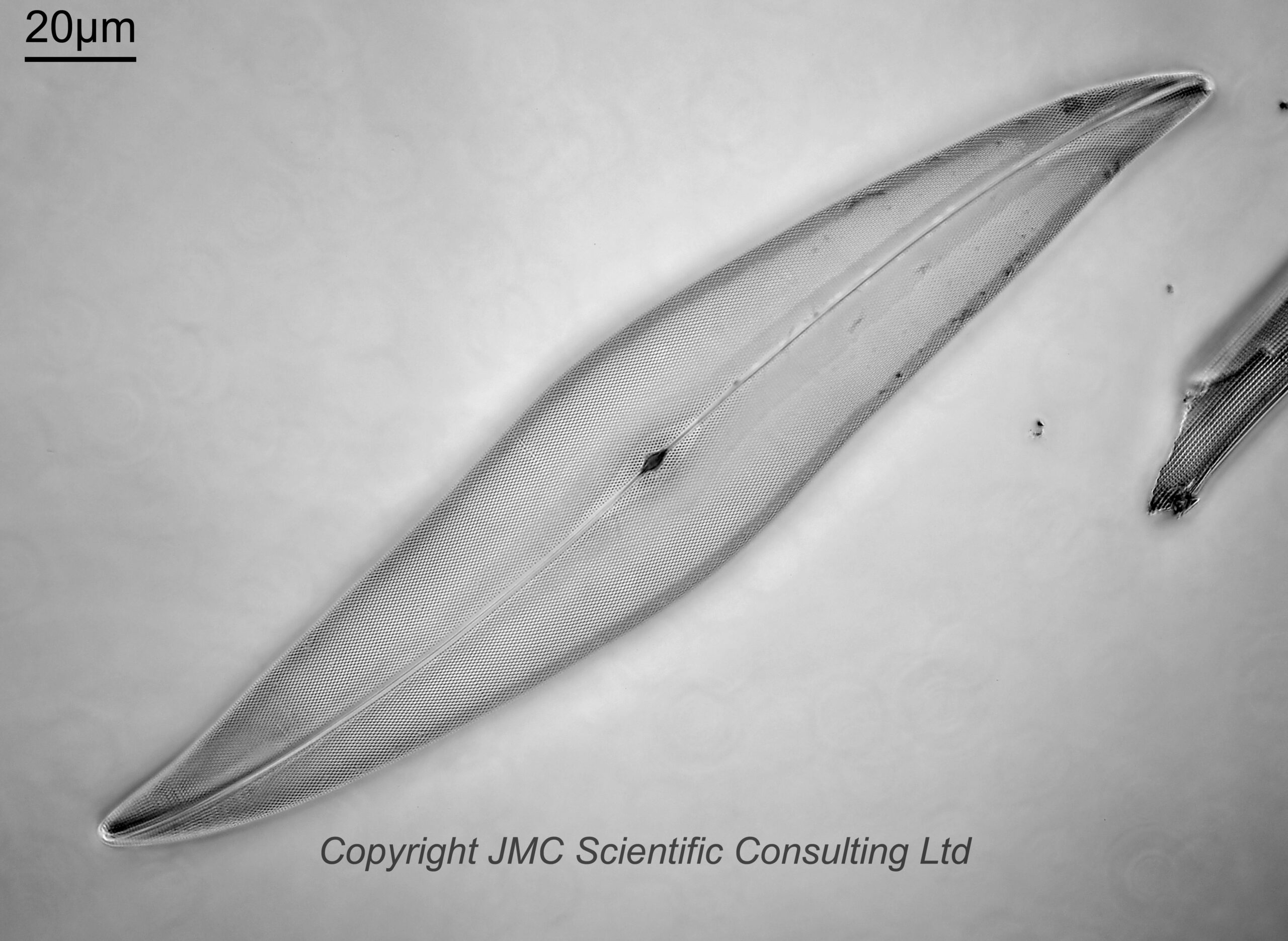
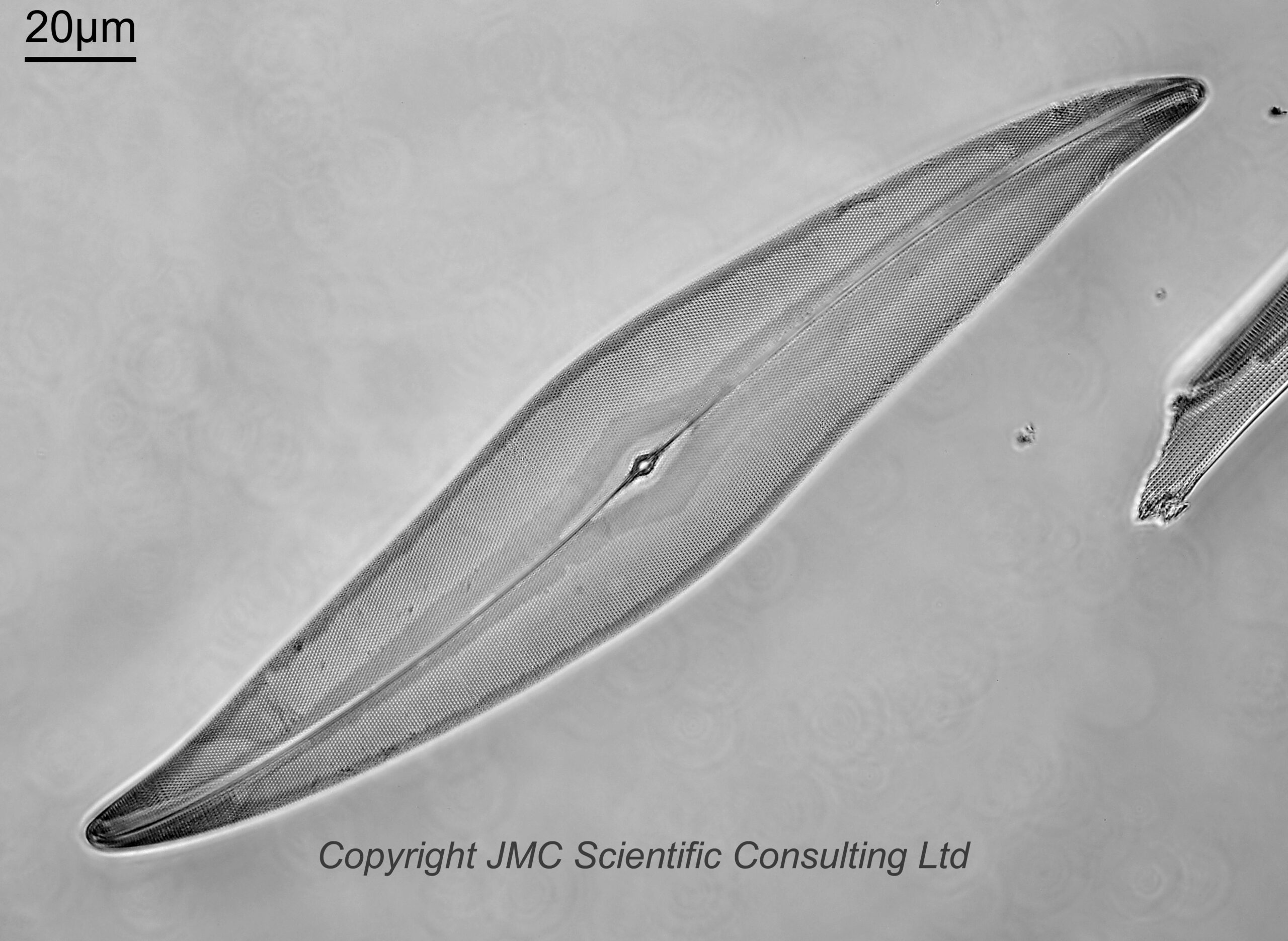
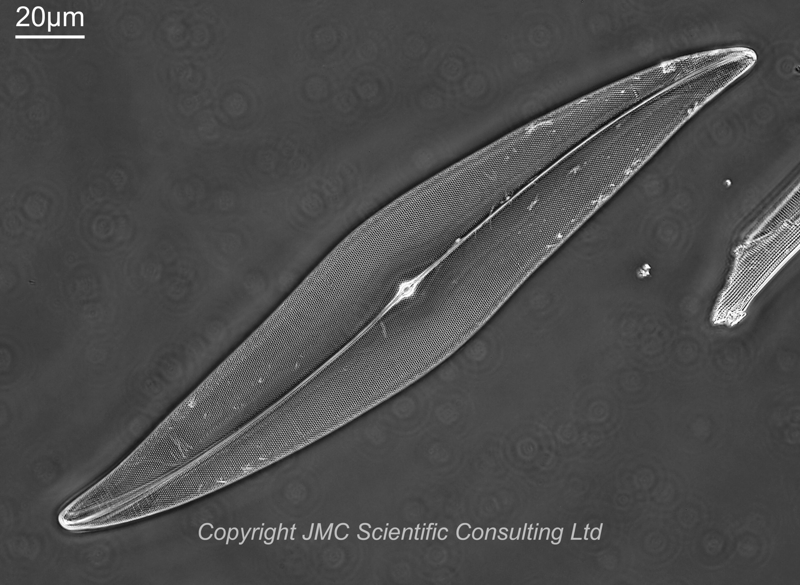
Enough talk. Images. Here are 4 images of a diatom called Pleurosigma angulatum from the slide by JD Möller. Imaging was done on my modified Olympus BHB microscope, using 450nm LED light, and with a monochrome converted Nikon d850 camera.
For these images I used a Leitz Heine condenser (this was not oiled to the underside of the lens, and was used without the top oil lens attached). The first two images were done with the condenser set to brightfield illumination, and with the iris on the objective fully open, and then slightly closed down. For the next image, the iris on the objective was opened back up, and the Heine condenser position moved to between brightfield and darkfield. This is supposed a phase contrast setting, and the image does look to be (at least partly) a phase one to me. Then for the final image the Heine condenser was moved to the darkfield position, and the iris on the objective left wide open. This a darkfield/circular oblique lighting image. This was where I must admit to a bit of a mistake. I should have closed the iris on the objective down a bit to make it more darkfield. Oh well, c’est la vie.
The images all show the dot pattern on the diatom nicely, but with variations in contrast between different areas, and have their own aesthetic qualities.
The Leitz Heine condenser was an interesting one to use for this, as by moving it up and down you can go from brightfield, through phase contrast, and to darkfield all with one condenser.
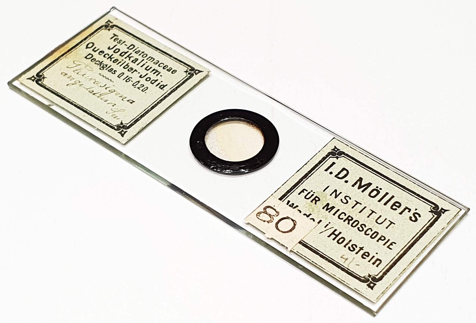
The diatoms were on a slide by JD Möller, and used the mountant ‘Jodkalium-Quecksilber-Jodid’, which is Potassium Iodide/Mercury Iodide. This is a high refractive index mount, with an RI of around 1.75-1.80 based on the information I have been able to track down. This is much higher than Styrax which was commonly used at the time, and this comes from an era before the likes of Naphrax, when a lot of experimentation was being done to find high RI materials for mounting diatoms for microscopy. Here’s the slide.
Now, the second part of this post – the objective that was used. This is a 40x Zeiss Plan Apo with a phase ring and an iris.
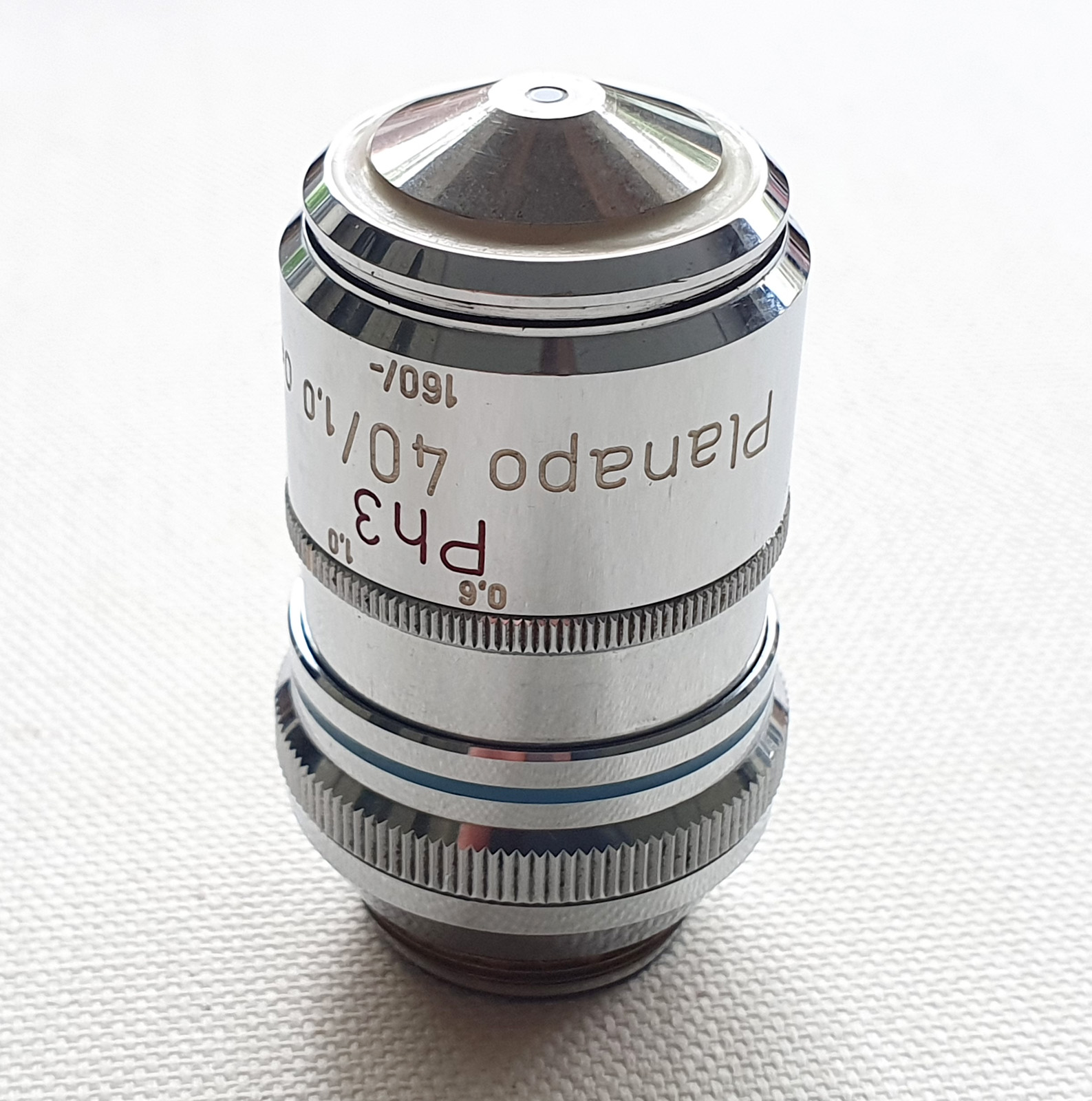
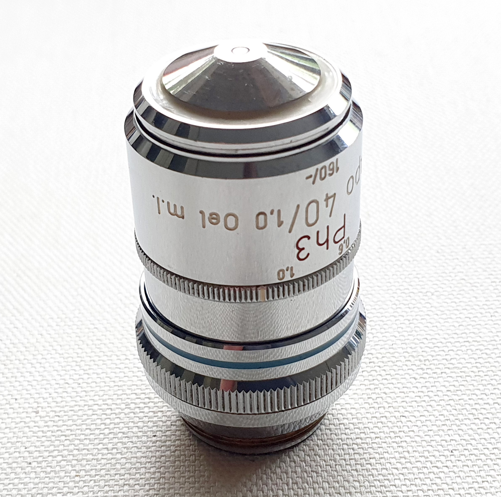
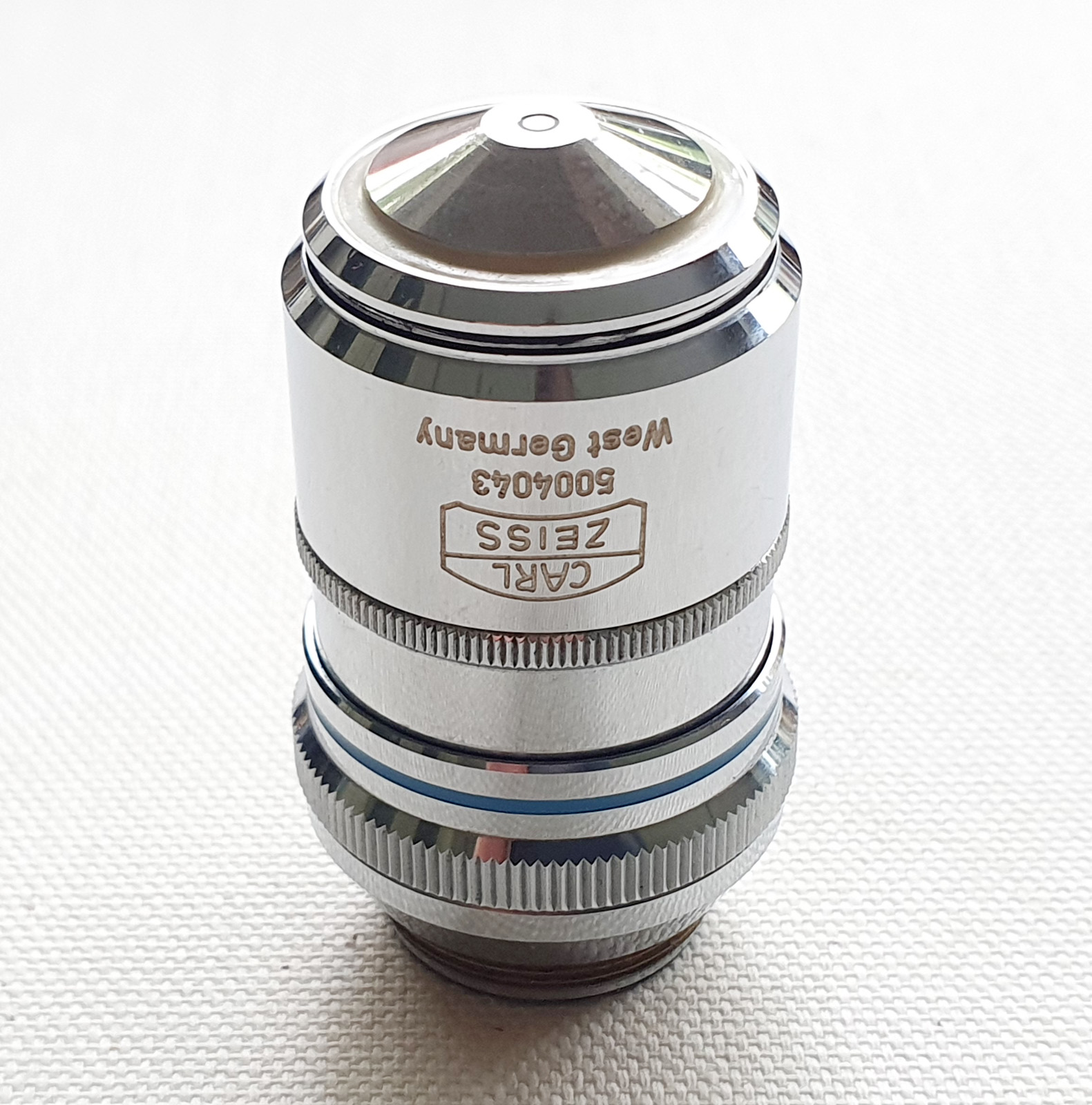
There’s a bit to unpack with this lens, so I’ll take you through the labels. This is a 40x objective. It is a high quality Plan Apo one. Plan means it is a flat imaging field, and Apo meaning apochromatic (corrected for chromatic aberrations across a wide spectral range). Plan Apo typically offer the highest optical quality from the range of lenses provided by a manufacturer. It has an an NA of 1.0, and is designed for use with oil immersion (Oel). It has an iris (m.I.) which can vary the NA between 1.0 and 0.6. Varying the iris can be useful when for example doing darkfield imaging. It it is also a Phase Contrast objective (Ph3) and has a phase ring if you look down it from the back. It is for 160mm tube length microscopes and can be used on slides with or without a coverslip (the ‘-‘ in the 160/- on the microscope barrel). All in all a very, very, useful and multifunctional objective, and would no doubt have been quite expensive when new.
As mentioned above, for these images I used the objective in combination with a Leitz Heine condenser which can be moved to provide brightfield, phase contrast and darkfield illumination all from the one package. This condenser and objective used together provide a lot of options for tweaking the image to give the desired final look.
As always, thanks for stopping by, and if you’d like to know more about this or other aspects of my work, I can be reached here.
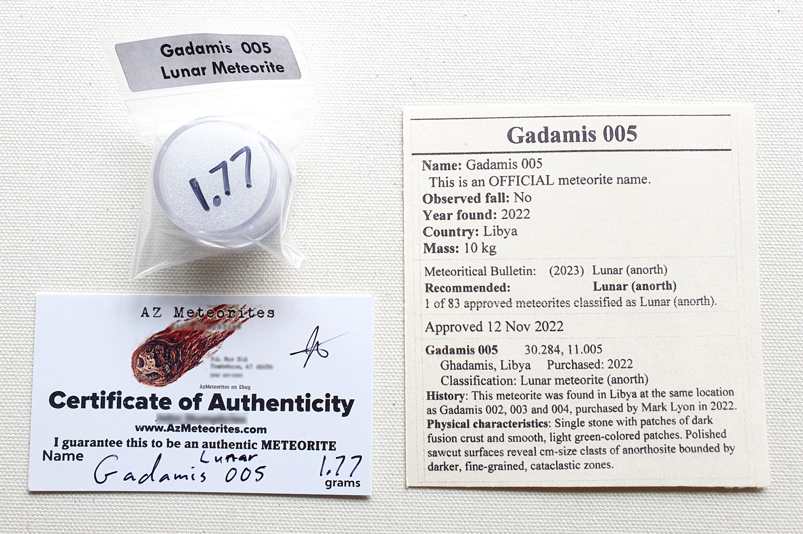
After the amazing Artemis II mission, it got me wondering, could I get some moon rock to look at under the microscope? Now, funnily enough I can’t go to NASA and ask for a small amount of lunar material from an Apollo mission, however there are ways to get rock which has come from the moon in the form of ‘lunar meteorites’. A quick search and I tracked down a US meteorite dealer (Azmeteorites on ebay) and bought 6 examples of lunar meteorites, with the aim of getting a range of different materials. The first of these arrived today – a piece of Gadamis 005, from a meteorite which fell in Libya.
Lunar meteorite Gadamis 005
When the remained arrive, the aim is to get these fragments thin sectioned, polished and mounted on microscope slides for imaging. Updates will come as and the projects progresses.
My space fascination goes back to childhood, as I am sure it does for many of us, and I first write to NASA when I was at junior school with a design for a space station based on a Space Shuttle fuel tank. A few months later they sent me a letter thanking me for my design and loads of little information brochures, which I read cover to cover, again and again (and still have in the original envelope). I may not be able to go to the moon, but perhaps I can still get to look at a piece of it up close and personal.
As always, thanks for reading, and if you’d like to know more about any of my research, please feel free to contact me (see here).