
Light microscopy is a powerful tool to help you understand how your product or formulation is structured. As with all imaging techniques though, depending on what you want to image, it is not without its challenges. When the Covid lockdown started, I bought myself a beaten up old Olympus microscope, with the aims of learning how it worked getting it up and running again, and with a long term goal of using what I’d learned to build a UV transmission microscope. Of course, things progressed pretty quickly as we shall see….
First though some of the results of my first attempt at UV microscopy. Taking the standard Olympus BHB microscope, and replacing the halogen light source with a 200W Xe lamp which is filtered to produce light mainly in the UV region from 250nm to 400nm, I took some images of a sunscreen formulation on a glass slide. This product is an oil in water emulsion (oil droplets suspended in a water based continuous phase), and with the UV absorbing component in the oil phase. This would be a nice simple one to try, as the two phases should look very different under UV.
For an objective lens, I used a Leitz 40x UV objective (which is discussed further here), to give me a good chance of getting as much UV to go through it as possible, and this is what a thin film of the sunscreen looked like imaged using a UV modified Nikon d810 camera (overall magnification about 400x).
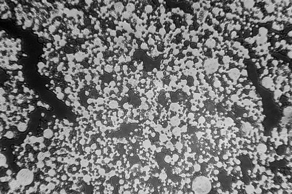
So, what are we looking at in the image above? The black areas are the oil phase, where the sunscreen is present (hence they look darker as the UV is being absorbed). In between the dark areas, is the water phase. You can see individual oil droplets, but also some areas where the oil droplets are starting to merge together as the emulsion structure begins to collapse.
While doing the images, I noticed that if the microscope cover slip was touched, the water and oil phases would ‘flow’ as a result. To capture this behavior I took a video clip using the UV modified camera (watch it with the sound off unless you like to noise of cooling fans from the light source).
What are we seeing in the image above? Firstly, at the start of the clip, the lighter grey water phase flows from left to right, taking some of the individual oil droplets with it. This is then followed by the oil phase as it collapses and the darker sunscreen containing oil droplets fuse together. The video is darker than the photograph, as there is so little UV getting through to the camera – in order to get anything at all on the video the ISO setting on the camera had to be turned up to 10,000!!!
Overall, a success for a first experiment. The sunscreen containing oil droplets look like they should under UV, and it was even possible to get some video footage of the behavior.
What is going on here though, why is everything so dark in the video clip? The light source was a 200W Xe lamp, focused using a collimator into the back the microscope – there should have been loads of light. This is where the issues with dealing with optical systems comes in to play. This microscope was not designed for UV imaging, and so every lens, every mirror, every beam splitter will be be absorbing some UV. Imaging is done through a photoeyepiece in the top of the microscope which projects a image into the camera. This in itself is a relatively complex piece of optics designed for use in visible light rather than UV. Also the 200W Xe light source was just ‘shone’ into the back of the microscope with the hope that the alignment would be good enough. Add all these together and a lot of the light will be lost before it even reaches the camera. Using a spectrometer it was possible to estimate how much was being lost. Firstly an irradiance scan taken with the cosine corrector of the collection fiber about 3cm in from the collimator on the light source.
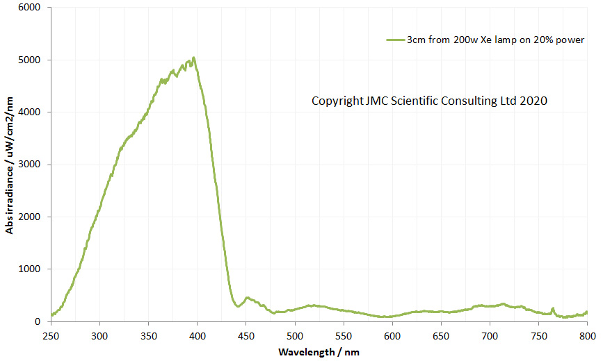
This light is producing a lot (and I mean a lot) of UV. I wear gloves, and UV safety goggles while using this light, as the risk of burning and eye damage is high. There is a good range of UV wavelengths though, from about 250nm up to 400nm.
Now a second scan with the spectrometer, with the cosine corrector up against the exit of the photoeyepiece at the top of the microscope (after the light has gone through the microscope, the condenser, the glass slide itself, the Leitz UV objective lens, and the photoeyepiece).
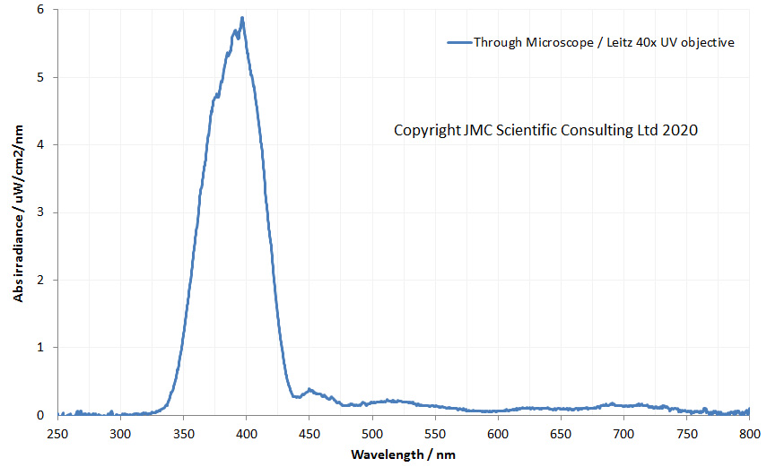
The light getting through the photoeyepiece is about 0.1% the intensity coming from the lamp itself. Also the wavelength range of UV has been reduced. Now there is nothing really below 350nm. This is because the microscope is not designed for UV imaging – the glass lens elements present absorb the UV, both in the glass itself and any coatings on them. This is why UV microscopy is so difficult – all the components in the optical train must be optimised for UV rather than visible light, especially if you want to get below 350nm.
There is another issue to consider as well – the filtration of the light before it gets into the camera. On my UV modified Nikon d810 camera, there is an internal filter which lets through light mainly between 320nm and 380nm, while blocking unwanted wavelengths. So as you can see, with the light getting through the microscope, I am only really seeing what is going on between 350nm and 380nm at the moment.
Future direction for this work is for me to build a UV microscope, rather than trying to adapt one to do the job – something capable of being used between about 250nm and 400nm. This will be a bit of along term goal though, as the challenges are many. Still, should be fun though…..
In the mean time if you’d like to know more about this or any of my other work, get in touch – you can reach me through my Contact page.