What feels like a long time ago, all the way back in 2020, when I first started my microscope journey, I made myself a condenser using UV fused silica instead of glass. This was so I could use it for ultraviolet microscopy (you can see the early post here). I always wondered how well it worked compared to, for example, the standard commercial Olympus Abbe condenser. Recently I found a way of visualizing the light cone produced by a condenser, and that is by using a uranium glass cube which fluoresces when exposed to UV. Today I want to share the results of a quick test with you, looking at how these condensers behave.
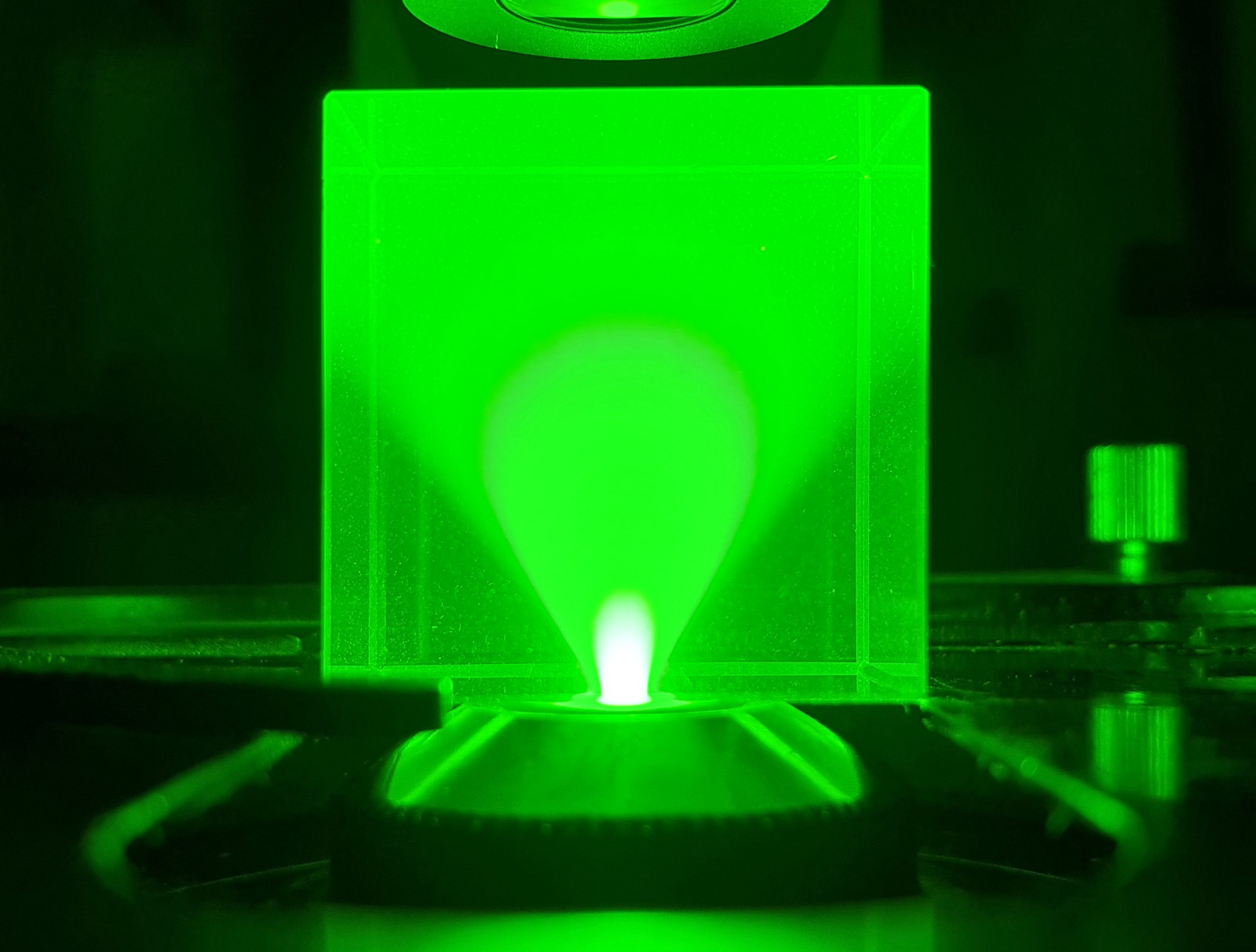
First, and image made with the standard Olympus Abbe condenser, with its iris fully open.
Standard Olympus Abbe condenser, fully open
The condenser is at the bottom of the image, and the light (from a 365nm UV torch) is coming through and hitting the uranium glass cube. The glass fluoresces where the UV hits it. The condenser is producing a nice light cone, with just under a 90 degree spread which is what would be expected in this setup.
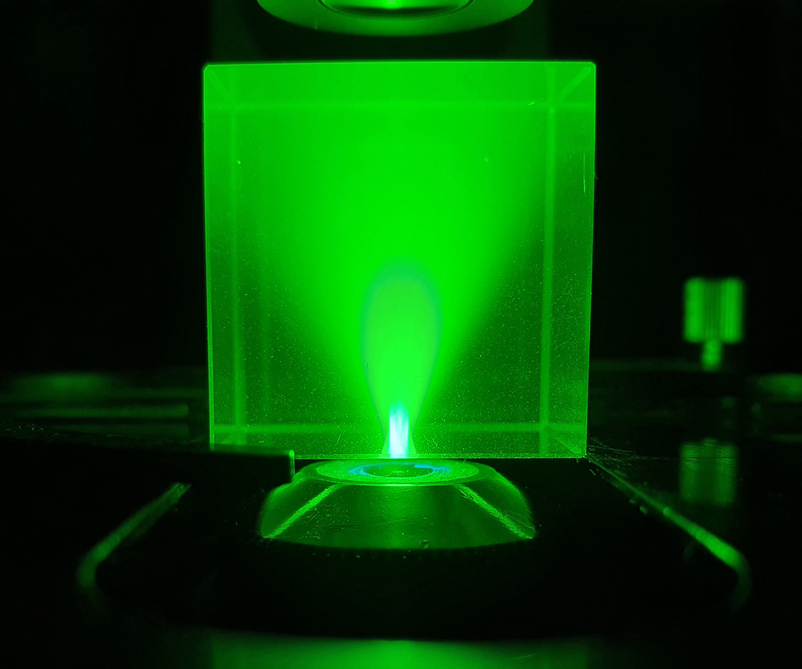
Next we have the UV fused silica condenser I made.
UV fused silica condenser, fully open
With my home made condenser, the edge of the cone is a bit less well defined than the one by Olympus, and I think the angle is slightly narrower. I am not hugely shocked that it doesn’t match the behavior of the commercially made one. Also, I had to move the condenser down slightly so the top of it was about 2mm below the glass cube, in order to get the brightest spot at the base of the cube. Again, this makes sense – I used a half ball lens as the top lens of the condenser, while the original was more of a ‘three quarter’ ball. As such mine would be expected to focus higher above the flat part of the lens. Unfortunately getting custom ball lenses ground would not be cost effective for me to consider. For what it is though, and for what it cost me, I am more than happy with its performance.
As a final thing, I want to show what happens to the light cone as the condenser iris is closed down (this was the commercially Olympus Abbe condenser).
Standard Olympus Abbe condenser, iris being closed down
Closing down the iris reduces the angle of the light cone, as expected, but it is nice to see this being demonstrated in practice.
Thanks for reading, and if you’d like to know more about my work, I can be reached here.
This post is a bit of a double whammy. First, I’ll share some diatom images from a microscope slide with a very unusual mountant – mercury iodide. Second, I’ll talk about the useful and multifunctional objective I used to take these images – a Zeiss 40x Plan Apo, with an iris and a phase contrast ring.
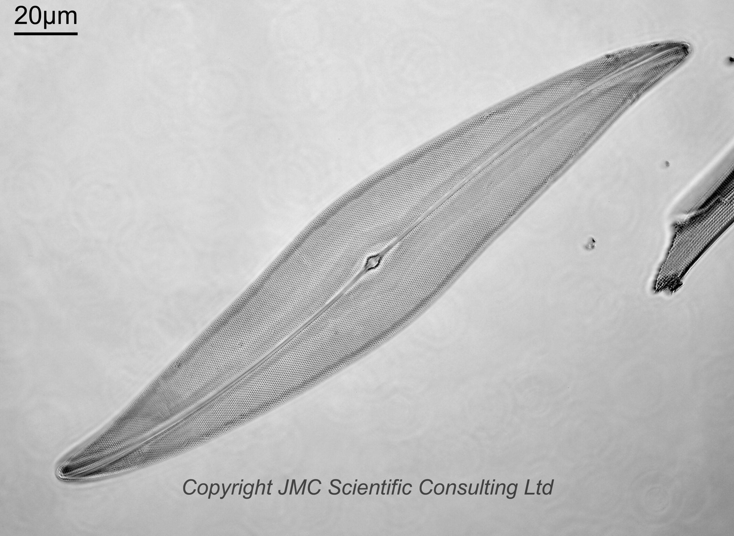
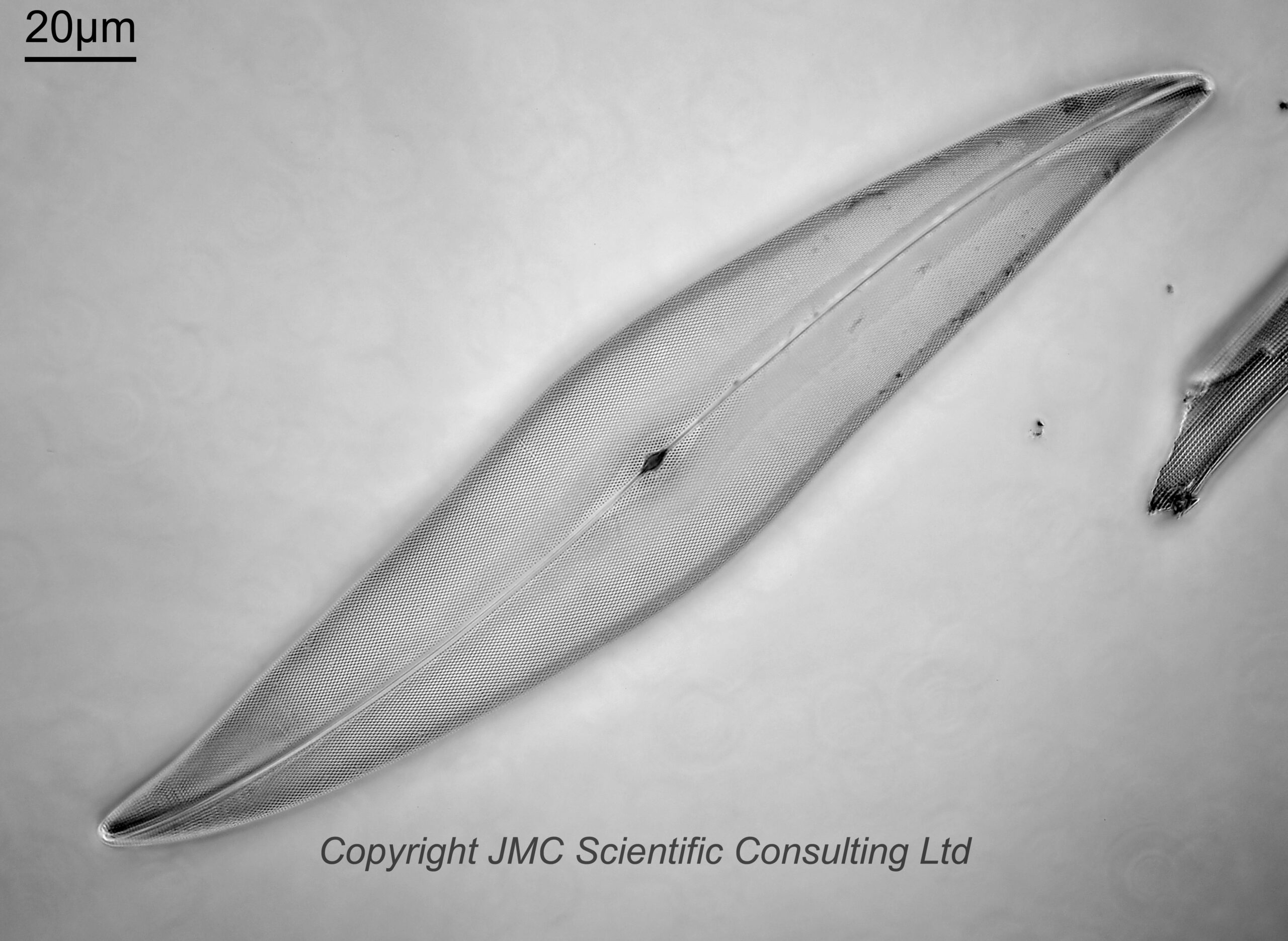
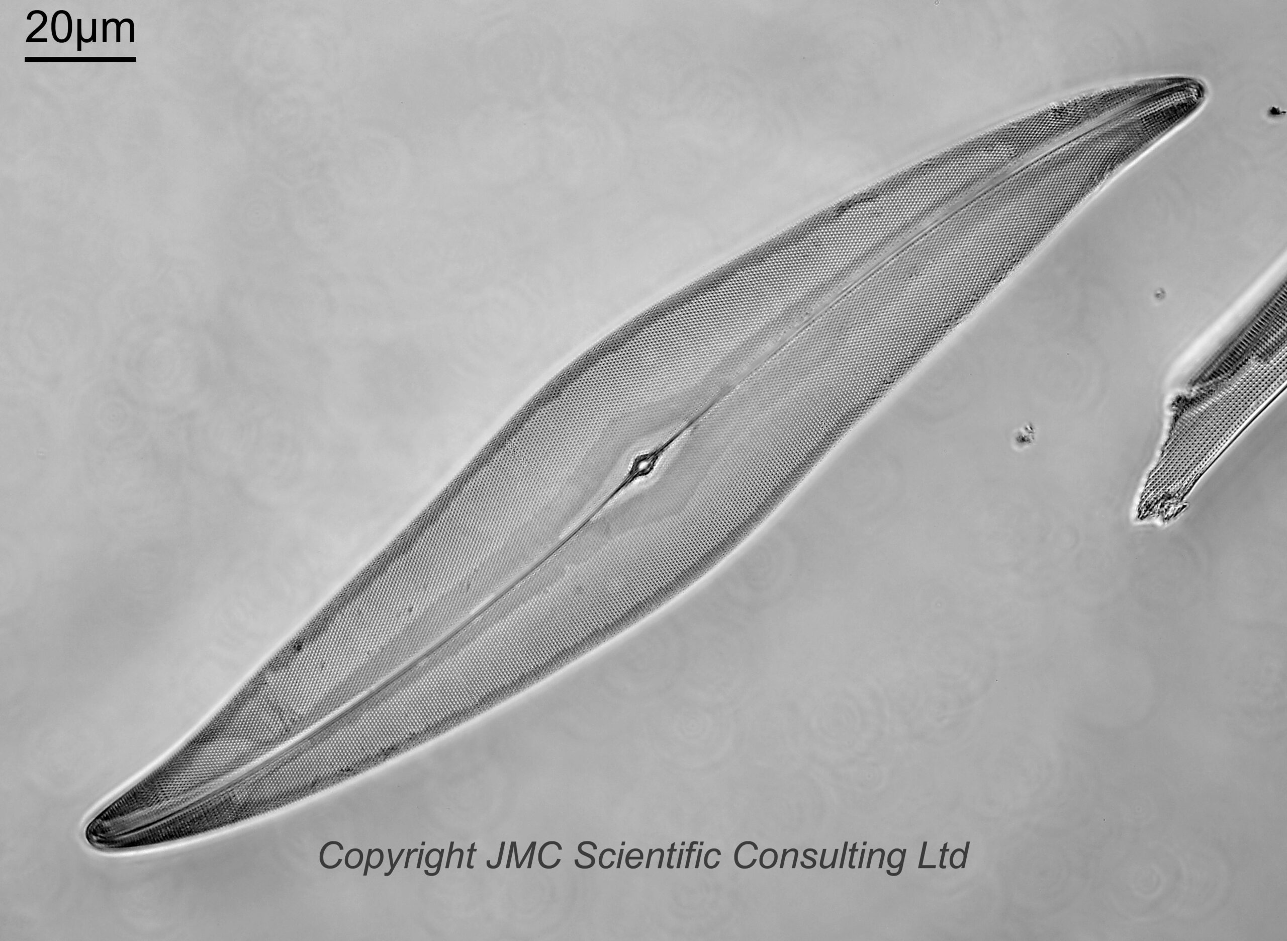
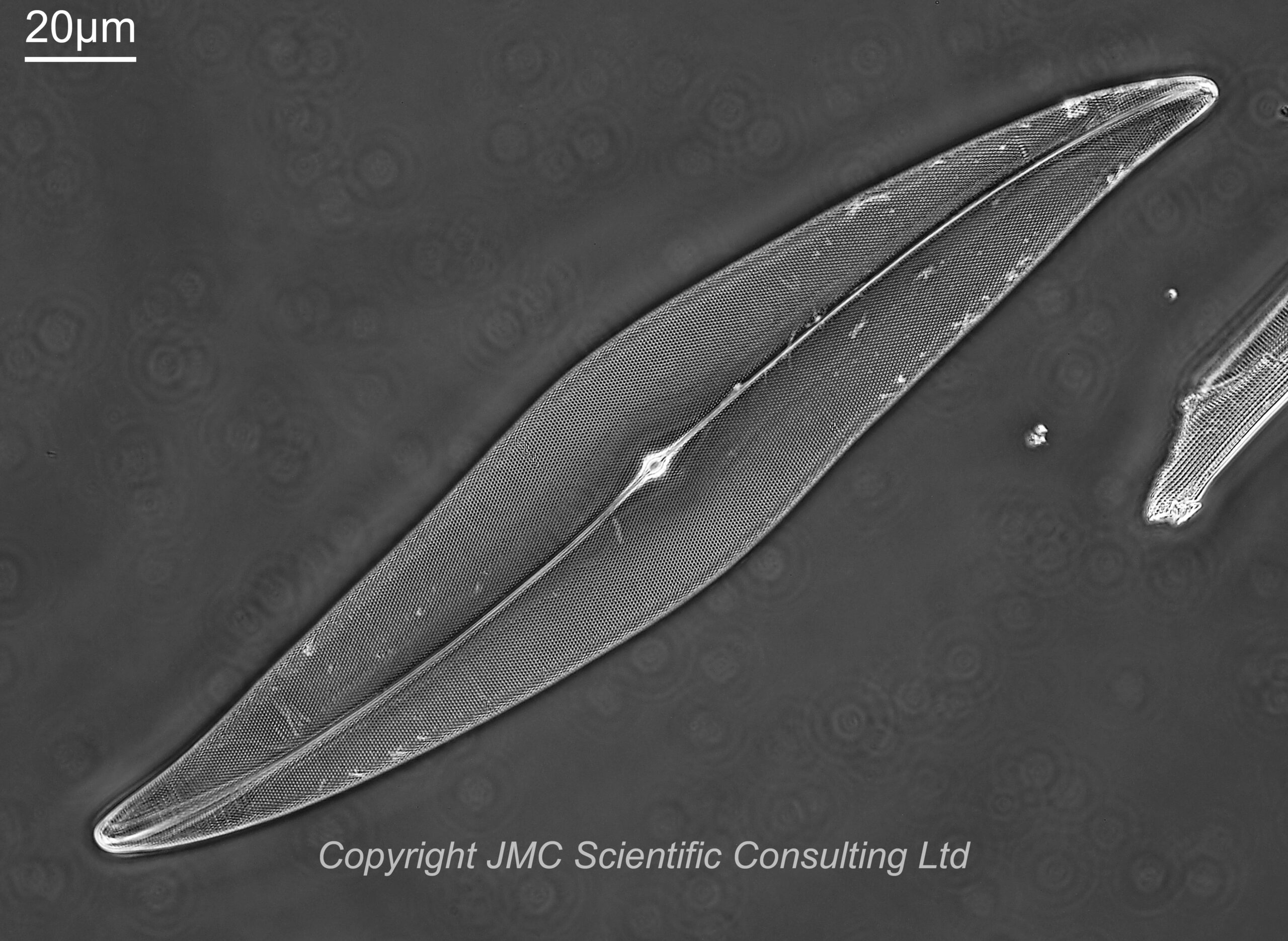
Enough talk. Images. Here are 4 images of a diatom called Pleurosigma angulatum from the slide by JD Möller. Imaging was done on my modified Olympus BHB microscope, using 450nm LED light, and with a monochrome converted Nikon d850 camera.
For these images I used a Leitz Heine condenser (this was not oiled to the underside of the lens, and was used without the top oil lens attached). The first two images were done with the condenser set to brightfield illumination, and with the iris on the objective fully open, and then slightly closed down. For the next image, the iris on the objective was opened back up, and the Heine condenser position moved to between brightfield and darkfield. This is supposed a phase contrast setting, and the image does look to be (at least partly) a phase one to me. Then for the final image the Heine condenser was moved to the darkfield position, and the iris on the objective left wide open. This a darkfield/circular oblique lighting image. This was where I must admit to a bit of a mistake. I should have closed the iris on the objective down a bit to make it more darkfield. Oh well, c’est la vie.
The images all show the dot pattern on the diatom nicely, but with variations in contrast between different areas, and have their own aesthetic qualities.
The Leitz Heine condenser was an interesting one to use for this, as by moving it up and down you can go from brightfield, through phase contrast, and to darkfield all with one condenser.
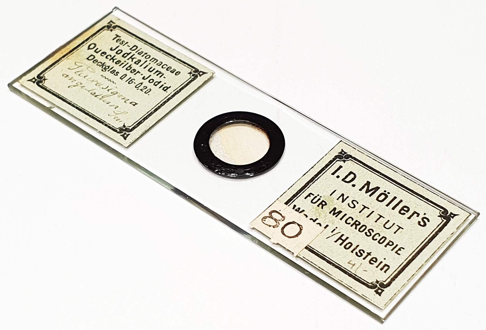
The diatoms were on a slide by JD Möller, and used the mountant ‘Jodkalium-Quecksilber-Jodid’, which is Potassium Iodide/Mercury Iodide. This is a high refractive index mount, with an RI of around 1.75-1.80 based on the information I have been able to track down. This is much higher than Styrax which was commonly used at the time, and this comes from an era before the likes of Naphrax, when a lot of experimentation was being done to find high RI materials for mounting diatoms for microscopy. Here’s the slide.
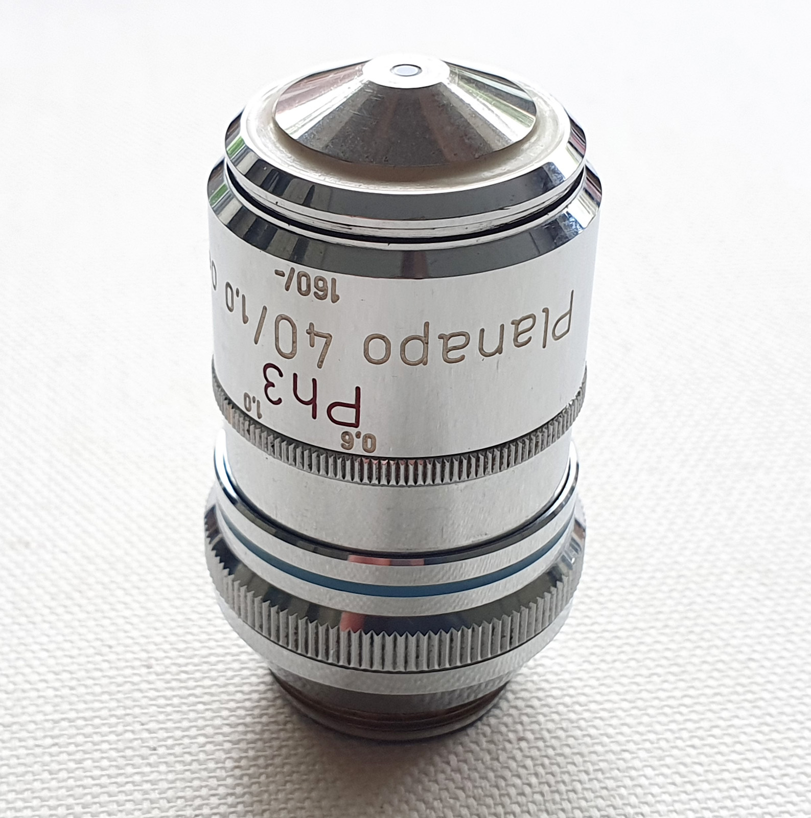
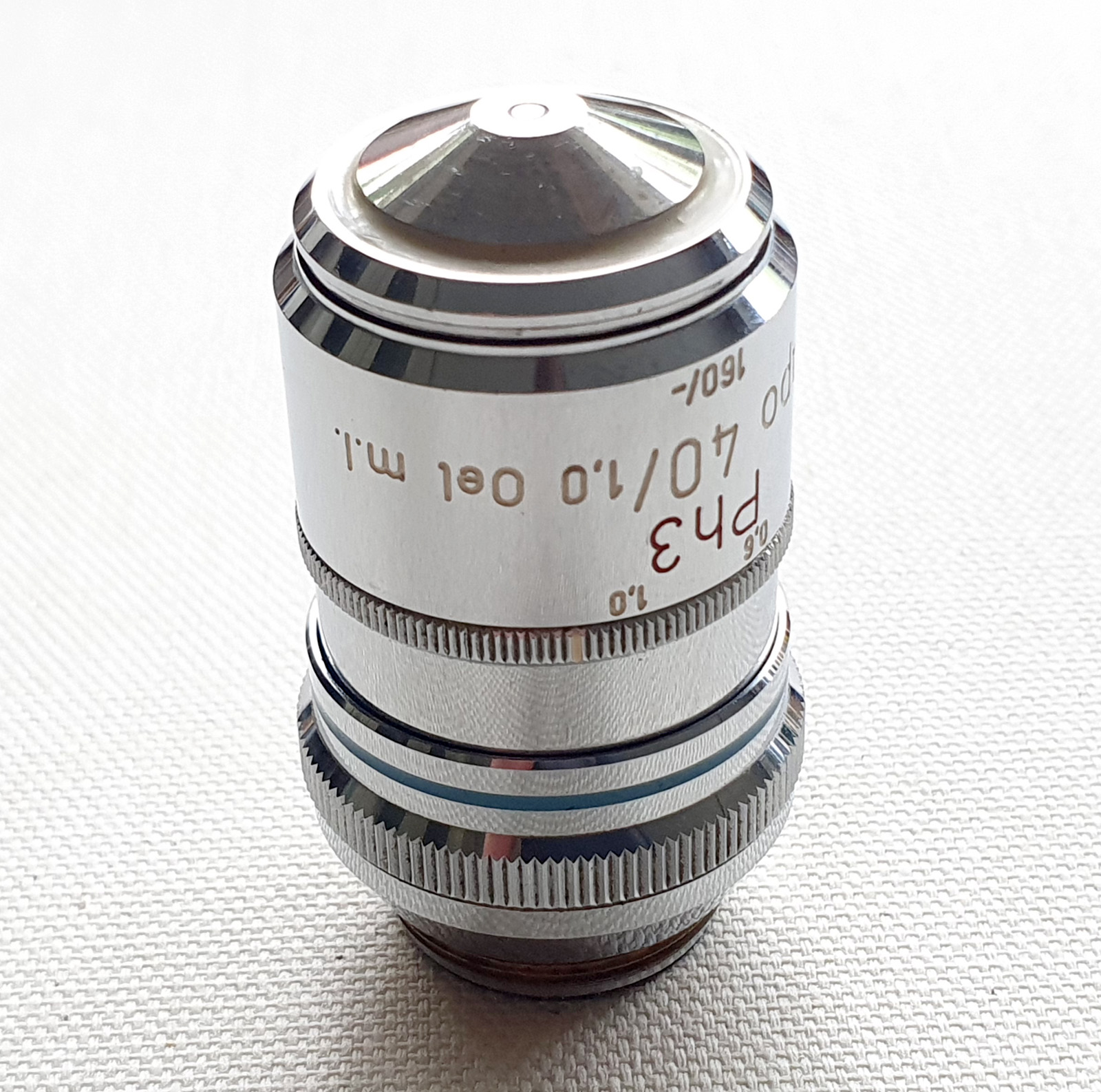
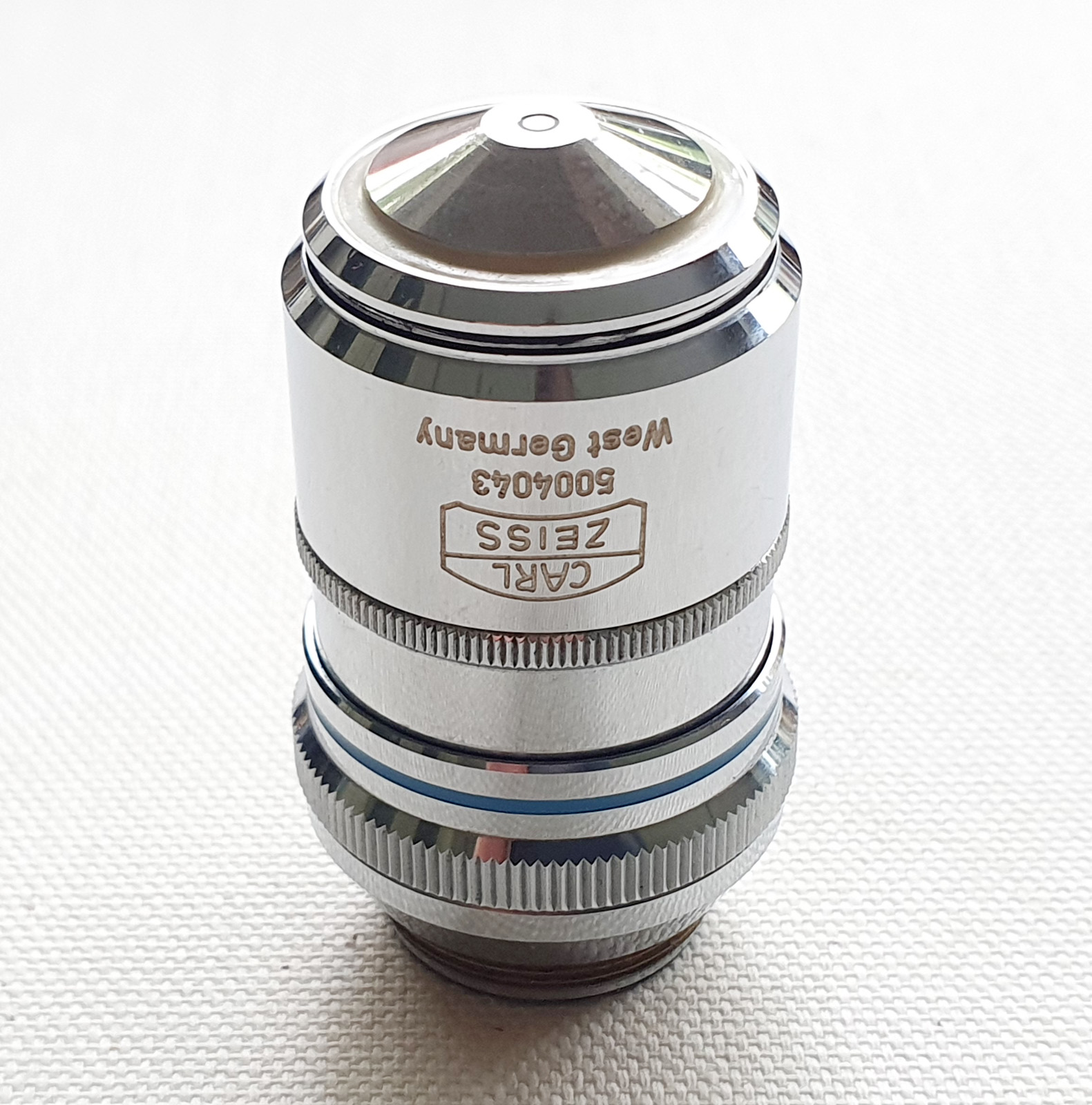
Now, the second part of this post – the objective that was used. This is a 40x Zeiss Plan Apo with a phase ring and an iris.
There’s a bit to unpack with this lens, so I’ll take you through the labels. This is a 40x objective. It is a high quality Plan Apo one. Plan means it is a flat imaging field, and Apo meaning apochromatic (corrected for chromatic aberrations across a wide spectral range). Plan Apo typically offer the highest optical quality from the range of lenses provided by a manufacturer. It has an an NA of 1.0, and is designed for use with oil immersion (Oel). It has an iris (m.I.) which can vary the NA between 1.0 and 0.6. Varying the iris can be useful when for example doing darkfield imaging. It it is also a Phase Contrast objective (Ph3) and has a phase ring if you look down it from the back. It is for 160mm tube length microscopes and can be used on slides with or without a coverslip (the ‘-‘ in the 160/- on the microscope barrel). All in all a very, very, useful and multifunctional objective, and would no doubt have been quite expensive when new.
As mentioned above, for these images I used the objective in combination with a Leitz Heine condenser which can be moved to provide brightfield, phase contrast and darkfield illumination all from the one package. This condenser and objective used together provide a lot of options for tweaking the image to give the desired final look.
As always, thanks for stopping by, and if you’d like to know more about this or other aspects of my work, I can be reached here.
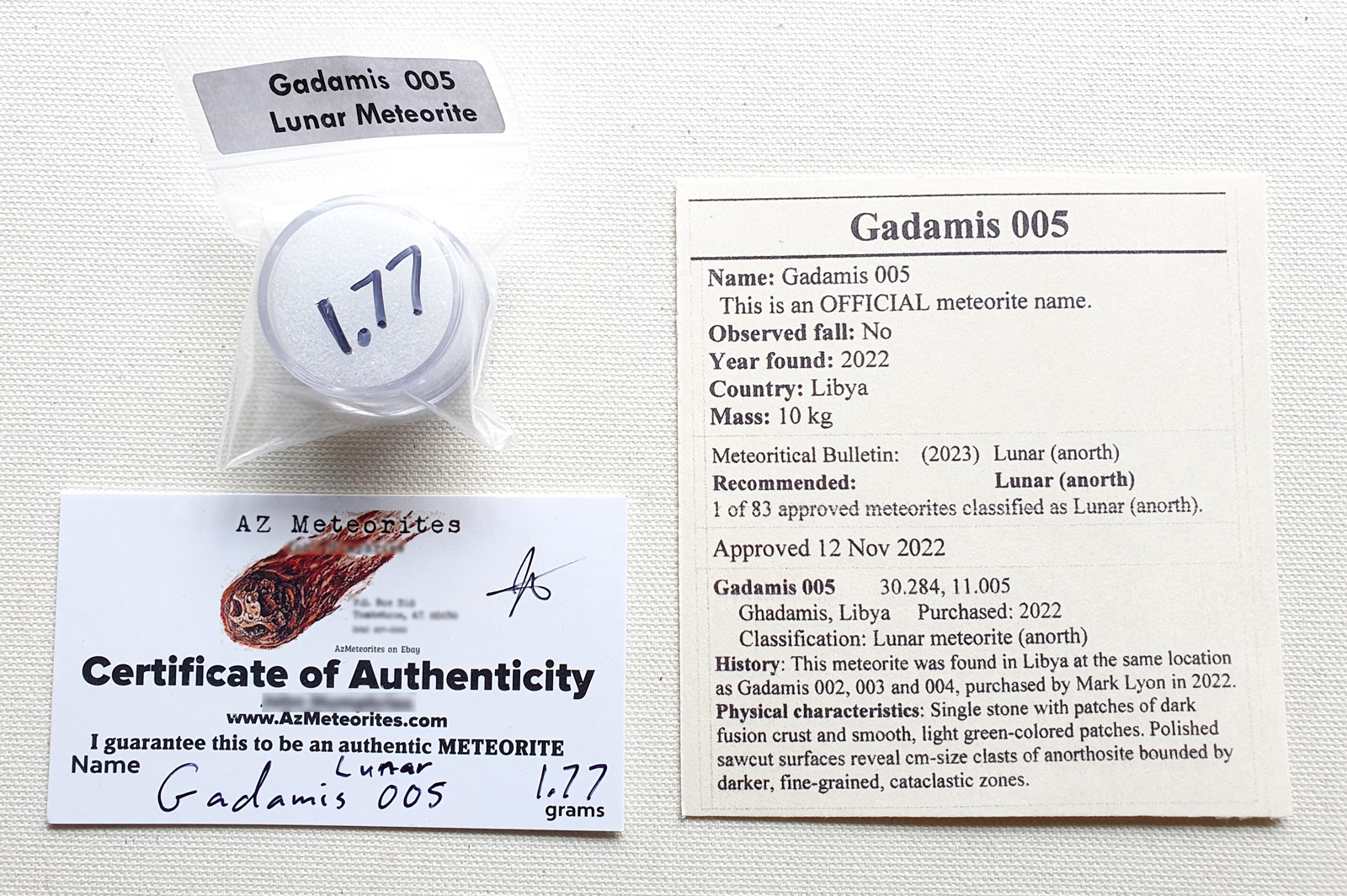
After the amazing Artemis II mission, it got me wondering, could I get some moon rock to look at under the microscope? Now, funnily enough I can’t go to NASA and ask for a small amount of lunar material from an Apollo mission, however there are ways to get rock which has come from the moon in the form of ‘lunar meteorites’. A quick search and I tracked down a US meteorite dealer (Azmeteorites on ebay) and bought 6 examples of lunar meteorites, with the aim of getting a range of different materials. The first of these arrived today – a piece of Gadamis 005, from a meteorite which fell in Libya.
Lunar meteorite Gadamis 005
When the remained arrive, the aim is to get these fragments thin sectioned, polished and mounted on microscope slides for imaging. Updates will come as and the projects progresses.
My space fascination goes back to childhood, as I am sure it does for many of us, and I first write to NASA when I was at junior school with a design for a space station based on a Space Shuttle fuel tank. A few months later they sent me a letter thanking me for my design and loads of little information brochures, which I read cover to cover, again and again (and still have in the original envelope). I may not be able to go to the moon, but perhaps I can still get to look at a piece of it up close and personal.
As always, thanks for reading, and if you’d like to know more about any of my research, please feel free to contact me (see here).
A vital part of my microscopy work is how best to store my slides to keep them protected and clean for the long term. For details on what I do read the latest my post on my museum website (DiatomImaging.com) where I show the MicroChamber shelf liner from Conservation Resources Ltd (see here).
The MicroChamber shelf liner (top and middle rows)MicroChamber shelf liner (top) and paper cutter
Seasons greetings everyone and as always, if you want to know more about my work I can be reached here.
Always nice to get an award for my imaging work, especially from such a distinguished organization as the Quekett Microscopical Club. I was awarded the 2025 “Barnard Certificate for Excellence in Photomicrography, Technical Category”, for my image of the diatom Pyrgodiscus armatus from a slide prepared by Michel Haak.
Quite a stunning looking (and rare) diatom from Brno, Tegl, Czech Republic. The image was taken on my modified Olympus BHB microscope, using 450nm slightly oblique illumination, and with a 63x Leitz Pl Apo NA 1.4 oil immersion lens. 145 images were stacked in Zerene (and yes I manually move the stage in between each image to build up the depth of field for the image), and I did final processing in Photoshop (mainly denoising and a little sharpening). The image above is a low resolution one, but the full sized one along with more details can be seen on my online museum (diatomimaging.com) website here.
If you are not familiar with the Quekett Microscopical Club, there’s more about them here. Founded in 1865 they are an amazing organization with over 150 years of microscopy history, and some of the most knowledgeable people I’ve met.
As always, thanks for reading, and if you’d like more information about my work I can be reached here.
Always fun to report a new article. At the end of last year I was asked to write a piece on the use of oblique lighting for the Postal Microscopical Society (an amazing group established in 1873). It was recently published in their journal, Balsam Post.
Oblique lighting helps to provide a more ‘3D’ appearance to microscope images, and can be very useful when looking at faint structures and features on subjects such as diatoms. For example, the image below – the diatom Triceratium robertsianum from King George’s Sound, on a slide by Samuel Henry Meakin, which was captured using oblique lighting from below.
Triceratium robertsianum, oblique lighting
The technique seems to have fallen by the wayside a bit these days, however it is a simple (and cheap) approach and can be done quite easily on all microscopes even if you don’t have an oblique condenser.
For anyone interested in microscopy and its history, I would strongly recommend joining the Postal Microscopical Society (see here). As well as being part of a really long running society with an immense wealth of knowledge, you have the option of signing up to receive slides from their collection on a regular basis to image.
As always, thanks for reading. My up to date publication list can be found here, and my contact details here. If you’re interested in seeing more of my diatom images, please checkout my online museum diatomimaging.com where I have thousands of high resolution photos, as well as background to the slides and techniques I use to capture the photos.
Being an avid microscopist of diatoms I come across some really beautiful slides. However occasionally I find one which is historically interesting as well. Today I’d like to share with you one of those slides. Here’s an image of the diatom – a fragment of Stictodiscus multiplex from Jérémie, Haiti.
Stictodiscus multiplex fragment
The slide was one I bought at Microscopium, the annual sales meeting and get together of the Quekett Microscopical Club (more about that here). It is (incorrectly) labelled as Stictodiscus buryanus, and there is no makers name.
The slide
As I was looking to ID the diatom, I went through Schmidt’s Atlas – Atlas der Diatomaceenkunde. And specifically I came across a diatom fragment on Plate 75, Figure 1 which looked suspiciously like mine. This was a fragment of Triceratium multiplex. Also, later there is an image of Stictodiscus multiplex (Plate 451, Figure 10). I think S. multiplex is the newer name for T. multiplex.
The similarity to the fragment in Plate 75 got me wondering – is the diatom on my slide the one used to make this illustration? A couple of experiments, putting them side by side and then overlaying one on the other has got me convinced that this is indeed the one used to make that illustration based on the shape of it and the dot pattern.
The fragment overlayed with Schmidt’s Atlas, Plate 75, Figure 1
The fact that algae have made these structures is amazing in itself. Factor in that some (like this one) are fossils that have been in the ground for millions of years, and the mind boggles. Then to think that I have a slide which was used to make such an important reference work as Schmidt’s Atlas, it is so cool (in a very geeky, nerdy way).
As always, thanks for reading and if you’d like to know more about my work I can be reached here.
Also, you can read more about this slide, and see a full high resolution image of the fragment, on my other site – the online diatom microscopy museum, Diatomimaging.com – here.
I was working on a client project recently which called for me to do some optical microscopy to image the droplets present in a skin cream. How you do microscopy has a huge impact on the nature of the images you get, and things like changing the wavelength of the light and direction the light comes from can have quite big effects on the final image and how it looks. I’ve seen various ‘qualities’ of images papers and scientific reports, and it has been my experience that many companies are losing technical experts from the their departments which means the experience of using things like microscopes is often disappearing. I thought I’d share some images of a topical oil in water emulsion using my modified Olympus BHB microscope and show the effect of changing the light source spectral distribution and lighting direction on the image, as well as going to high resolution to see what size features can be expected to be seen.
I’ll keep the product anonymized for now, but this is a topical skin cream with oil droplets in an aqueous matrix. A dot of cream was placed on a standard glass slide and a 0.17mm coverslip placed on top. This was gently pressed to flatten it out. The microscope is an Olympus BHB which has been modified to allow me to do UV work (although I am only using visible light here). Two objectives have been used, first a 20x Nikon Plan Apo NA 0.65 one, then a 63x Leitz Pl Apo NA 1.4 oil immersion one. Condenser was an Olympus Aplanat Achromat, used in brightfield and oblique configurations (and oiled to the underside of the slide when used with the 63x objective). 2.5x Nikon CF PL photoeyepiece. Monochrome converted Nikon d850 camera. Light source was a white LED light which was left unfiltered, or filtered using a 450nm, 40nm FWHM bandpass filter from Thorlabs. The microscope was focused just below the underside of the coverslip. Single images were taken and processed in Photoshop (denoised, sharpened – unsharp mask, and auto contrast). They were then cropped to 1600×1200 and kept at original resolution.
Enough waffle. First two images – brightfield lighting, white light and 450nm light, and 20x Nikon Plan Apo NA 0.65 objective.
20x Nikon Plan Apo NA 0.65 objective, brightfield, white LED light20x Nikon Plan Apo NA 0.65 objective, brightfield, 450nm LED light
Both brightfield images look pretty good. The droplets can be seen. If you go in close the 450nm light image is slightly higher resolution than the white light image. This is simple physics – resolution of a microscope setup is highly dependent on wavelength. The shorter the wavelength the better the achievable resolution for a given setup. White light contains a mixture of light from 400nm to about 700nm. This spread will have an ‘average’ wavelength which is longer than the 450nm filtered light. Also, having a range of wavelengths puts greater stress on the optics being able to focus all those wavelengths to the same point. The objective is a Plan Apo (Plan – flat field, Apochromatic) and is a good one, but it will always be harder to correct for a wide range of wavelengths vs a small range.
Next oblique images. Oblique lighting, white light and 450nm light, and 20x Nikon Plan Apo NA 0.65 objective.
20x Nikon Plan Apo NA 0.65 objective, oblique lighting, white LED light20x Nikon Plan Apo NA 0.65 objective, oblique lighting, 450nm LED light
Changing the lighting to oblique (basically pulling the condenser slightly to the side) has the effect of creating a pseudo-3D image compared with brightfield, as it produces directional shadows. The effect is subtle here, and is easier to see when oblique and brightfield are put next to each other. Again, both the white light and 450nm light images look good, and the 450nm light one has slightly better resolution as before. I am a big fan of oblique lighting and use it a lot for my diatom photos. Brightfield images can be quite flat, but oblique lighting can make the structures in an image more tangible. Oblique lighting tends to be overlooked these days in favour of other approaches to improving contrast in images, which I think is a bit sad. It is such a simple technique and so much cheaper than something like Differential Interference Contrast (DIC). In fact oblique lighting has been called “poor man’s DIC” in the past.
While a 20x objective image is often good enough to see what is going on, sometimes higher magnifications and resolutions are needed. I also imaged this slide using a 63x Leitz Pl Apo NA 1.4 oil immersion objective, using 450nm light, and with brightfield and oblique lighting. Some people are scared of oil immersion, but it’s not that bad and enables the highest NA objectives to be used (and therefore the highest resolutions to be reached). These images are shown below.
63x Leitz Pl Apo NA 1.4 objective, brightfield lighting, 450nm LED light63x Leitz Pl Apo NA 1.4 objective, oblique lighting, 450nm LED light
Yet again, both images look good. However as expected the brightfield image is quite flat, while the oblique image has that pseudo-3D look about it, which can help with visualizing smaller features. For instance I picked on one of the small droplets in the image and used ImageJ to measure its diameter (which turned out to be 498nm).
63x Leitz Pl Apo NA 1.4 objective, oblique lighting, 450nm LED light, small droplet, 498nm
Keep in mind with these 63x objective images that the depth of field is tiny – probably a few hundred nm, so very minor shifts in the stage will bring things in and out of focus, especially the smaller droplets. Sub micron resolution is not too hard with these high NA objectives, and it should be possible to see things down to about 4-500nm without too much difficulty. Below that things get a bit tricky without getting more complex in your approach.
Optical microscopy is a very powerful technique for the skin care formulator as it allows emulsion structure to be visualized which can impact everything from product stability to appearance and aesthetics on application. As with all imaging techniques the more you know the more you get out of it, and simple tweaks like choosing the right wavelength of light to use, and even how you illuminate your sample can have a marked effect on the image produced. While this can help with just seeing what is going on, if the images are to be used in marketing the product, getting the right ones can make the difference between a successful product and one which doesn’t live up to its potential.
As always, thanks for reading, and if you’d like to know more about my work, I can be reached here.
Most of my posts relate directly to my research in one form or another. However with some I just like to share information that I am unlikely to use myself, but may be of use to the work that someone else out there is doing. Today’s post falls into this second category.
There is a microscopy technique called Differential Interference Contrast (DIC) which many hail as being amazing and producing unique and fascinating images. There are various online resources which go more into the theory of this (such as the Leica site here). It’s quite complicated to do and requires some very expensive components, and as such this pushes it out of the realm of many microscopists (myself included). However given its complexity and my scientific curiosity I do keep an eye out for parts occasionally, and I recently managed to get a few prisms from an Olympus Epi NIC (Nomarski Interference Contrast, which is Olympus’s name for DIC) as I was wondering what the transmission through these looked like. I managed to get 4 prisms, one each for the 5x, 10x, 20x and 50x objectives. Unlike the usual astronomical prices which people often want for these, I get them for about £50 in total including one of the objectives. There are a bit beaten up, and will need re-gluing into their holders as the original glue has failed, however the filters themselves don’t look too bad. Below are the filters.
Olympus Epi NIC (DIC) objective filters
The transmission through the filters (as measured on my Ocean Optics FX spectrometer) is given below.
Olympus Epi NIC (DIC) objective filter transmission
I had suspected that these filters would have good transmission down into the UV and indeed they do. So, they are not normal glass, but more exotic materials, presumably quartz. This undoubtedly contributes to the high prices for these items.
By the way, a technique called ‘oblique lighting’ can be used to produce pseudo 3D type images. While perhaps not as powerful as DIC, it’s results can be pretty spectacular, and it is much, much easier and cheaper to do. This is something I do for my diatom images (see my other website Diatom Imaging if you like microphotos of diatoms).
Anyway, a short post today just to share some info. If you have found this I hope it helps you with your work. As always, thanks for reading, and if you’d like to know more about my work, I can be reached here.
During my research into UV microscopy I’ve come across references to various different objectives. Some of these were refracting objectives, with quartz and sometimes other exotic lens elements. Other are reflecting objectives, which are based on the use of mirrors (and in some cases refracting elements as well). Today I’d like to share some findings on a recent acquisition – an American Optical 50x NA 0.56 reflecting objective. To start with some images of it.
It’s quite a tiny little thing. RMS threaded, and comes in its own box with a plastic push on cap to protect the front face. It is 50x and NA 0.56 and is designed to be used dry. It is marked ‘AO’ and ‘Spencer Made in USA 946485’. Mine is also engraved with ‘UC ZOO 66079’. This has been professionally done (not scratched on as these things are so often done), and presumably a University Zoology department. On the front of the objective there is a small opening and the 3 legged ‘spider’ that holds the small tiny mirror. Here is the entry for it from an AO catalogue.
50x AO Reflecting Objective catalogue entry
Interestingly (and incorrectly) the catalogue entry states this is a catoptric objective. There is at least 1 refractive element to it and this can be seen in the image of the rear of the lens near to where it is threaded. It was designed to be used in spectrophotometric work from ultraviolet through to infra-red.
Next I measured the optical transmission through it in the UV (UV is more of my area than IR).
AO objective transmission
Transmission remains relatively flat between 280nm and 420nm, and I have no doubt this is a true UV capable objective (something with normal glass elements would not transmit down to 280nm). Overall % transmission is low as there is some clipping of the beam by the objective, and is nothing to worry about.
Next some tests on the microscope. I mounted it to my Olympus BHB microscope using a 8mm RMS spacer (just to get it approximately parfocal to my other objectives). Imaging was done with an Olympus Aplanat Achromat condenser, brightfield, optimized for each photo. Monochrome converted Nikon d850 camera. 450nm LED light.
First a Beck Optronics Silverpoint test slide, used to check alignment of reflecting objectives, which showed no obvious streaks which would indicate the mirrors weren’t aligned properly (thankfully).
Silverpoint test slide image
Changing the focusing of the slide showed nice circular features as it went in and out of focus, with the 3 legs of the spider being visible.
Silverpoint test, varying focus
Next a resolution test. Three images of a Newport test slide. The AO objective, and then 20x NA 0.65 and 10x NA 0.45 Nikon Plan Apo objectives.
Resolution test, 50x AO NA 0.56 reflecting objectiveResolution test, 20x Nikon Plan Apo NA 0.65 objectiveResolution test, 10x Nikon Plan Apo NA 0.45 objective
The resolution for the AO reflecting objective (with its 0.56 NA) is certainly up there with the 20x Nikon NA 0.65. The AO image is more ghostly than the other two (which are Plan Apochromats) which I often see for reflecting objectives. In hindsight this was not the best test to do, as the image was so small with the 20x and 10x objectives, that the features were approaching the size of the pixel resolution on the camera. However it highlighted no major issues with the objective.
Finally some images of a diatom – Amphiplueria lindheimerii – single images using 450nm LED light. First image with the AO objective, with the condenser iris open.
50x AO image, condenser iris open (brightfield)
Next a brightfield image with the 20x Nikon NA 0.65 Plan Apo objective. Compared with the Nikon, the AO objective shows some field curvature (seen as the ends of the diatom go out of focus), but it is not designed to be Plan so this is not a huge surprise. It could also to be due to my ‘hybrid’ microscope setup.
20x Nikon image
Final image, the AO objective with the condenser closed down to produce a darkground effect (this happens when the iris opening in the condenser is smaller than the front mirror of a reflecting objective).
50x AO image, condenser iris closed down
Overall, the American Optical 50x NA 0.56 reflecting objective is a nice addition to my collection of quirky and ultraviolet objectives. It being RMS threaded makes it easy to use. As for finding one if you want to try it, I wish you good luck. As with many of these unusual objectives they were never made in large numbers, and rarely come up for sale. However, it is ‘rarely’, and not ‘never’, so keep your eyes out and you never know. I got mine on ebay.
As always, if you got this far, I thank you for your attention, and if you think I can help with your research I can be reached here.