
As a scientist, technical problems, and especially tricky technical problems, tend to get me all fired up. This one started about 6 months ago as a thought experiment – can I differentiate between different sunscreen ingredients through the use of UV photography? A seemingly simple question, it turned out to be a very very complex problem, and required equipment that I’d never used before. Well, 6 months on, and I have answer to my question. This is the tale of the approach I took. Oh, and to any manager which says, “don’t bother me with details, just tell me if you did it?”, that is about the most damaging thing you can say to a scientist. The details are what makes the work special……
Ok, so let’s define the parameters here. Choose 2 sunscreen ingredients with different UV absorbing properties. Spread them on a substrate. Image them using UV photography, and aim to be be able to tell them apart based on the images produced. ‘Why bother?’, you may ask. How about this, if you can differentiate between sunscreen ingredients you can tell which ones are left behind after washing or over time. If you can tell how much UV is being absorbed, you can get a feel for how much protection you have. What is the relative spreading of different sunscreens in your formula – does one spread better than another? Competitive analysis, does a competitor have a spread of UVA and B protection, and how does it last?
How to tackle the problem. There are a number of issues with this one. As I want to image 2 sunscreen ingredients, ideally one which is primarily UVB protecting, and another which is UVA focused, I need a light source capable of producing UVA and UVB in a controlled way, and at high enough levels to allow photography to be done. This is the first problem. Sunlight has very little UVB, and is not very reliable (especially in the UK). My UV flashes only produce UVA. My Ocean Optics light source which does produce UVB, has a 600 micron fiber, which isn’t really going to light up anything for photography. What’s the alternative then? I more powerful light source. I found a Hamamatsu LC8 on eBay, which is normally used by the electronics industry for UV curing. This has a very powerful 200W Mercury Xenon (HgXe) lamp, and an internal filter which prevents most of the visible and IR light from being emitted. The end result is a light which consists of mainly 250nm to 450nm, with intense spikes from the mercury. A hugely expensive light new, I found one for £200 on eBay, with about 500 hours left on the lamp before it needs replacing. One quick purchase later and I had a lovely LC8 UV light. This is a powerful light source – all work done here was done while wearing UV safety goggles, and not looking at the beam. You have been warned. Ok, so what does the spectrum of the light look like? I measured the output with my Ocean Optics FX spectrometer.
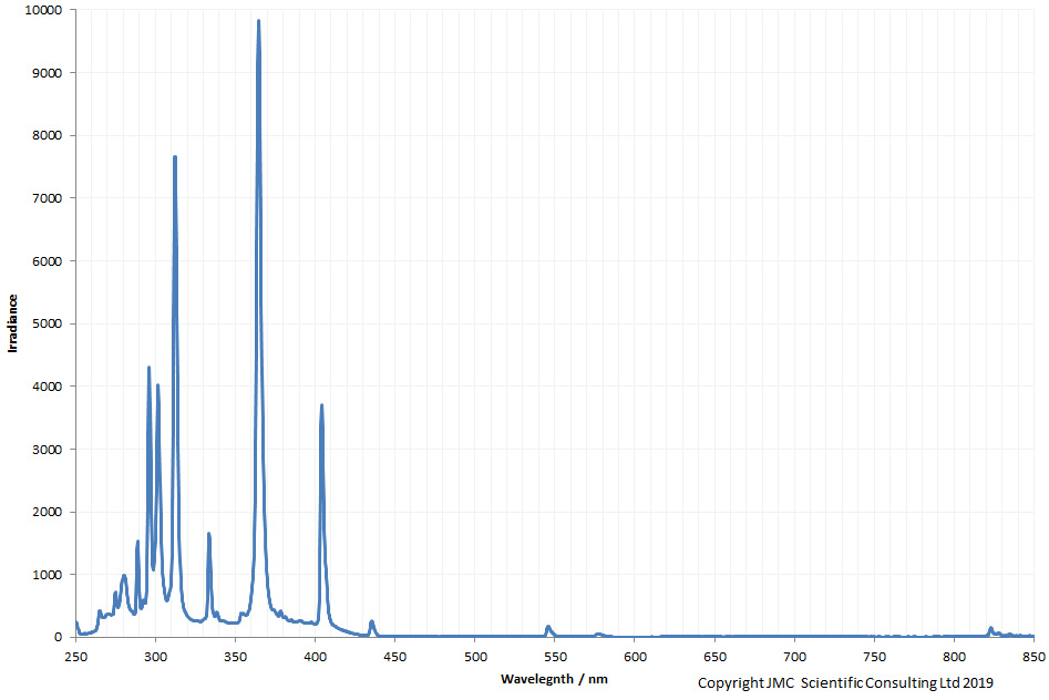
As can be seen the lamp is heavily weighted towards the UV, with very little light above 450nm. This is great for UV imaging, as eliminating the longer wavelength light means less likelihood of contamination of the image by non-UV light (the discussion on out of band blocking by UV will have to wait for another day).
Next step, how to capture the images? This is an interesting one, I could try direct reflectance photography, however I wanted to try something different here – UV induced fluorescence photography. With this type of imaging the light source is filtered to illuminate the subject with either UVA or UVB, and the fluorescence this induces is then recorded with the standard camera. This needs to be done in darkness, with no other extraneous light as obviously any other light will overpower the fluorescence. In this situation, the sunscreens aren’t the fluorescing components. Depending on their transmission profiles, they will absorb certain wavelengths of UV and prevent the paper behind them from fluorescing. So a UVA sunscreen filter would absorb UVA and prevent the paper from fluorescing when illmunated with UVA. Likewise a UVB sunscreen should do the same when hit with UVB.
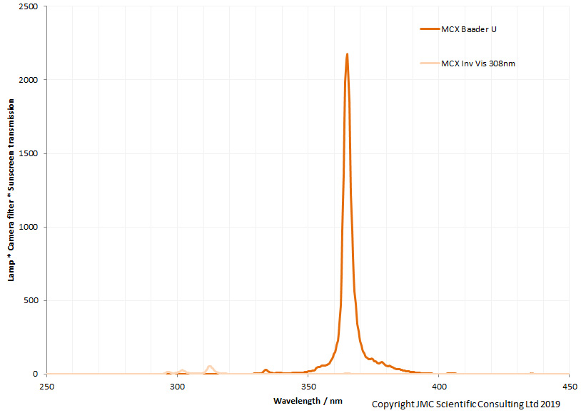
Equipment wise, camera – standard Canon EOS 5DSR. Lens, I went for my Nikon Rayfact 105mm UV lens, as it’s a good lens with macro capability, and and it was on the camera. Filters, 2 needed (one for the UVB region and one for UVA) and these will be key to splitting the sunscreen behaviour in two regions. I went for a Baader U for the UVA region, and an Invisible Vision 308nm for the UVB region. I’m not going to share transmission of these filters here, as those are available online, however what happens to the light from the LC8 when shone through these? This is shown below.
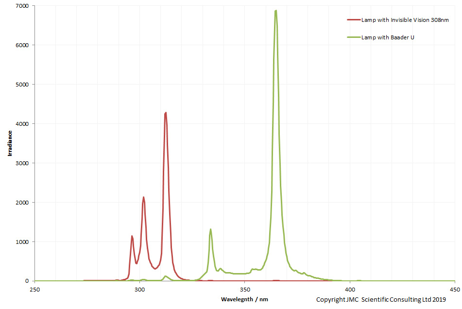
The filters do a good job of isolating 2 regions within the UV – the Baader U results in a big peak around 365nm (UVA), and the Invisible Vision 308nm filter gives a big peak around 311nm and two smaller ones around 300nm (UVB).
At this stage then, I have a light source, camera, lens and filter. The first test is to define a set of imaging conditions for each filter to enable me to compare images in the UVB and UVA regions. Why do this? The main reason is the camera response drops with wavelength, but also there is more UVA than UVB from the lamp. To compensate for this, the camera exposure for the UVB image will need to be longer than the UVA image, but how much longer? This leads to the first experiment – take a Labsphere diffuse reflectance standard (which reflects the same amount of light in the UVA and B regions) and image this with both filters across a range of different exposures. Of course I keep the f stop and ISO the same for all these. Then I plot the response of the camera RAW files against exposure, and I get the following.
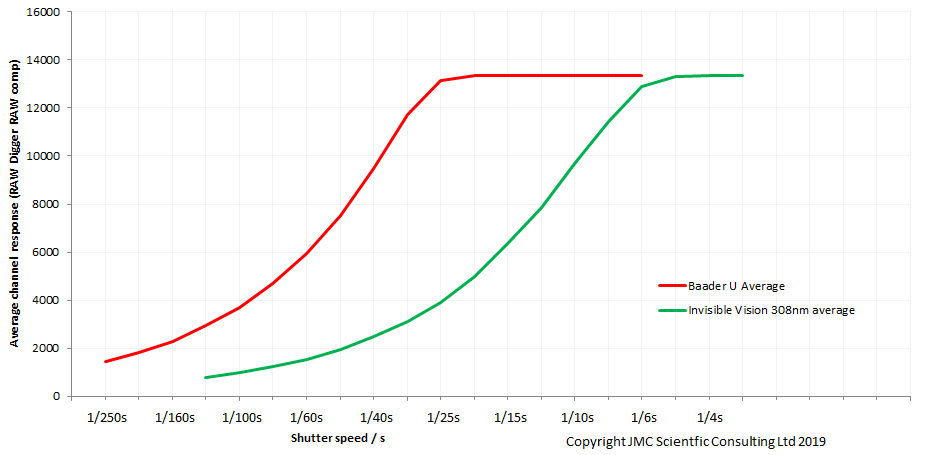
A nice controlled response for both filters – as the exposure time increases the image gets brighter (channel response increases). In the mid section of the graph, away from the light and dark extremes, this equates to about a 2 stop difference between the Baader U and Invisible Vision filters. Or in other words, for the UVB images I need to have about 2 stops more light than the UVA ones.
So I have light, camera, lens, filter and relative exposure times sorted out. What next? Sunscreen filters. I settled on 2 filters, Parsol 1789 (avobenzone) which is a UVA and partial UVB filter, and Parsol MCX which is a mainly UVB filter. These are produced by DSM, and DSM kindly provided me with a small sample of both of these filters for my work here. I spread the MCX directly on a PMMA HDD6 plate normally used for in vitro SPF testing. The 1789 was more complex, as I had to make a solution in ethanol and spread that on the HDD6 plate and allow it to dry. After a couple of attempts to get the thickness right (Goldilocks – not too much and not too little), I ended up with relatively thick layer of MCX and a good layer of 1789 for testing. I measured the transmission through both of these, to see how they compared.
The MCX is mainly a UVB absorber, although I had a thick layer, so that ended up going higher into the UVA than I really wanted – a thinner layer should be more UVB focused but this is a proof of concept experiment. 1789 absorbs both UVA and B, but more UVA. They key thing at this stage was that they were different in how they absorb UVA and UVB.
I now have samples ready. First thing then is a theoretical assessment – combine the lamp, camera filter and sunscreen transmission spectra, and do I get a difference in how I would expect them to be imaged. These theoretical plots are given below.
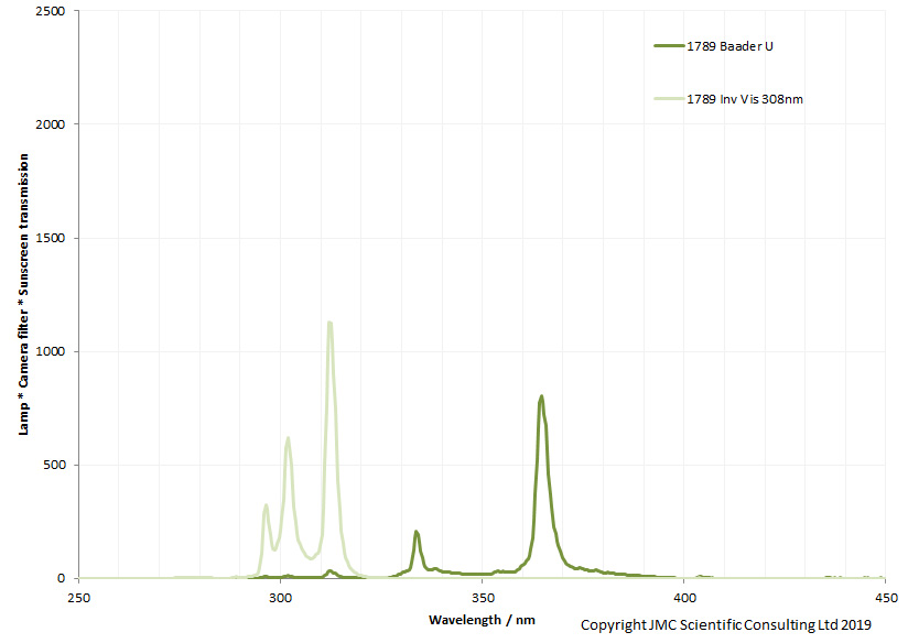
Looking at these 2 sets of graphs, the 1789 sunscreen would be expected to absorb some but not all the light in the UVB and UVA, but to transmit slightly less in the UVA than the UVB. It is a UVA absorber so this would make sense. MCX is mainly a UVB absorber, and expected to transmit much more in the UVA than UVB. In other words, they should behave differently when imaged – the 1789 should absorb some UVA and UVB and look slightly dark in both fluorescence images, while the MCX absorbs virtually all of the UVB and should look black in the Invisible Image as it’ll absorb pretty much all the UVB and prevent the paper background from fluorescing.
And now, how do the images look? Images were taken at 2 stops apart of the 2 sunscreen films, using the Baader U to filter the light, and then the Invisible Vision 308nm filter.
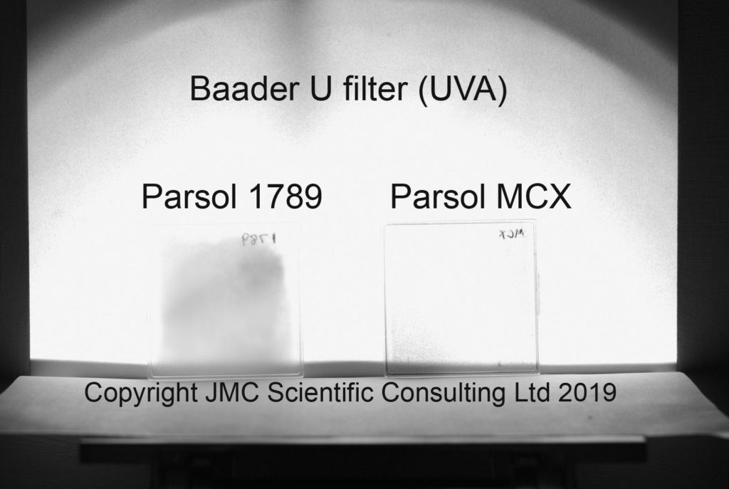
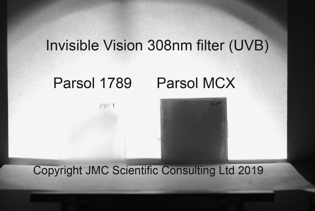
The good thing is that the 2 sunscreen filters look different depending on whether they are being imaged using UVA (with the Baader U) or UVB (Invisible Vision 308nm filter). The darker the film, the more light is being absorbed by the sunscreen and the less the fluorescence of the background. The Parsol MCX is absorbing much more UVB than UVA as expected (it is darker in the UVB image), and looks black then the fluorescence image is captured in UVB. The Parsol 1789 is absorbing slightly in the UVB and more in the UVA, so there is less fluorescence in the UVA illuminated image, and so looks darker when lit with UVA.
Success, it works, it is possible to differentiate between different type of sunscreen filters by a mix of UVA and UVB fluorescence photography!!!!!
However while it works, there are some issues when we compare the images. The sunscreen film thicknesses were not optimised here. As this was a proof of concept, the aim was to show whether sunscreens could be differentiated using imaging, and as a result I used quite thick films, especially of the MCX. In hindsight this was a bad idea. A thicker film results in a broadening of the bands the films absorb, and actually makes it harder to split them apart using the imaging as they overlap more. The coating of 1789 was relatively thin, as therefore it isn’t absorbing as much UV as it can, and the resultant fluorescent image isn’t as dark as it could be.
Also, the Baader U filter I used has quite a wide transmission range in the UVA. Ideally to help better differentiation between the UV regions, I would use a narrower bandpass UVA filter for future work. More filters, more money, so that may have to wait for now.
This is a perfect example of what happens when it comes to reporting results, and someone asks ‘never mind the details, did it work?’, just hold your tongue and remember it is the method that gets the results. If you can’t define the method there is no result. If you can break an experiment down into its constituent parts you can apply that skill to a wide range of problems.
What have I learned? This was one of the tougher experiments I’ve done, and as such was much more rewarding to see the result. In doing so I have learned more about UV lighting and filtering and how I can image behaviour in UVB, something extremely challenging to any photographer, especially using a high street camera. I’ve also learned more about sunscreens and the effects of film thickness. I’ve also pushed sunscreen UV fluorescence imaging forward into new areas, which I hope will eventually enable consumers to make more informed choices about sunscreen usage, with the eventual aim of reducing the incidence rate of skin cancer. I call that a good experiment.
I’d like to thank DSM for supplying me with 2 samples of sunscreens for me to test. All work presented here was funded by myself, and if you think this would help with your research, or you’d like to know more please contact me here.