
I’m a bit of dinosaur when it comes to the idea of ‘modelling’. As an experimentalist, I like build and test and then refine my idea, rather than rely on models. Also I’ve been involved in far too many projects where the term ‘model’ and ‘hypothesis’ get used interchangeably, resulting in huge issues which could have been resolved by just doing a few experiments. However there is no doubt that at times and when used properly, modelling can produce useful insights for projects.
With my UV microscope build I am converting an old Olympus BHB microscope into something I can use for doing transmission microscopy down to and below 300nm. At these wavelengths glass becomes opaque and lenses need to be made from materials such as quartz, UV fused silica, or calcium fluoride. And in a microscope there are a lot of lenses which need to be swapped out (as discussed here).
The condenser lens is positioned just before the sample and focuses the light onto the sample – a rather important role. The standard Abbe condenser on my BHB actually did a good job of letting UVA though (see here), but was blocking the UVB. Not unexpected really, as it is just glass after all. In fact, after being reflected through 90 degrees by the mirror below the stage the light then goes through 4 lenses before reaching the sample – the field iris lens, the auxiliary lens, and then 2 lenses in the Abbe condenser – none of which are suitable for UVB. To try and understand a bit more about the light movement and behaviour in these lenses, it was time to delve into the murky waters of optical lens design software. So it was time to grab a fresh cup of extra strong coffee and jump in…..
As a novice in this area, I thought I’d try a free piece of software which had some online tutorials – WinLens3D. The first thing to try was to produce a model of the 4 lenses below the stage. Unfortunately one of the lenses in the condenser is an odd shape, so I had to make an assumption for that one that I’d treat it like a half ball lens (a hemisphere). Creating a model with 4 lenses, gave the following.
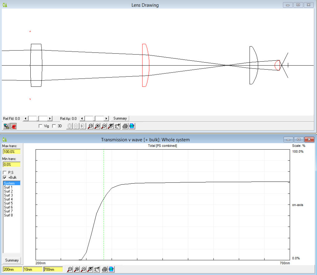
Moving from left to right, the 4 lenses in the stack are the field iris lens, the auxiliary lens, and then the 2 lenses from the condenser. This is a rough model, based on some of my measurements, so will not be 100% accurate. The good thing about this type of modelling software, is that in addition to looking at how the light moves through the lenses, the optical properties of the materials can be used to calculate a theoretical transmission spectra for the system, and this is shown in the graph in the image above. Assuming they are made from BK7 (a common glass for lenses) transmission starts to drop at 400nm, before reaching essentially zero at 300nm and below. With this you can see why normal glass is no good for UVB imaging. However with the model, you can change the materials the lenses are made from and see what effect that has. Changing from BK7 glass to UV fused silica gives the following.
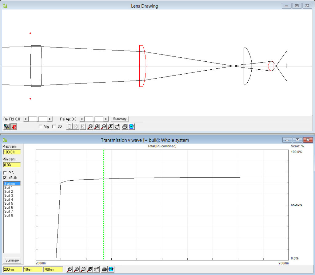
Changing to UV fused silica alters the light movement through the lenses slightly – as expected as the actual focal lengths of a specific lens design will change with refractive index of the material it is made from. However the biggest difference is in the transmission spectra. UV fused silica has great UV transmission, and as you can see the predicted transmission plot now shows a pretty much flat transmission curve down to 250nm, well into the UVB region. The software then does something a bit odd though – the transmission plot drops straight to zero at 240nm. I actually think this is a quirk in the software, as the fused silica should be good down to around 220nm. I suspect the data for the silica just stops at 250nm. Overall, moving to UV fused silica looks good – the model seems to predict good transmission, and the change from glass while slightly altering the light path should not make it unusable.
What to do about the condenser? I have a vintage Zeiss quartz microscope condenser currently waiting for me in the US to be collected the next time I visit, but Covid has put all those plans on hold for now. In the mean time, is it possible to modify an existing condenser by replacing the glass elements with UV fused silica ones? Using an existing condenser is the preferred option, otherwise it’d need custom machining work in addition to new lens, and the costs would rise very quickly. Taking a spare condenser apart presented the first challenge. One of the lenses was secured by a ring that had been glued in place in the factory. Having tried polar solvents, non polar solvents, heat, cold and various other methods to free it off nothing worked, and I resorted to the tried and tested approach of ‘hit it with something hard’. I got the lens out but not in any form which was useful. It did however leave me with the metal condenser housing which could be reused. The lens itself was 35mm diameter, which is an odd size for my supplier to source a replacement. To fix this I bought a 30mm filter ring and glued it in place where the old lens was. This allows the use of 30mm diameter lenses, which are much more common. I currently have one on order, and will update when it arrives.
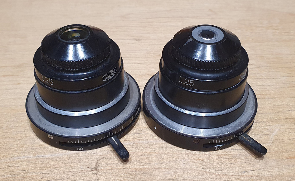
The top part of the condenser has a very odd shaped lens in it. It looks to be based on a ball lens, which then has a section sliced from it, and a chamfer ground into it as can be seen below.
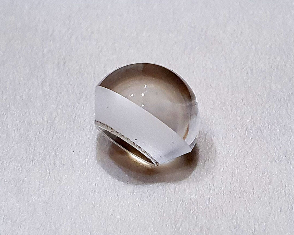
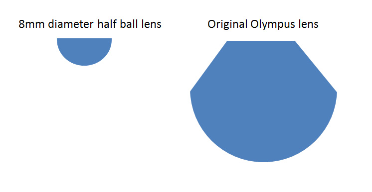
This is a not a common shape, and after trying multiple suppliers have currently given up on trying to find someone who can make this in UV fused silica. If I win the lottery, I’ll come back to getting one custom made, but it’ll have to wait for now. Looking at the shape though, it got me wondering whether a half ball lens would work. In fact it was a half ball lens that I used in the WinLens3D modelling above, and it looked like it should do the job. Half ball lenses are a bit more common, although I was looking for a large diameter one, which is much rarer. In the end I found an 8mm diameter UV fused silica one at Knight Optical here in the UK. This was much smaller than lens it would replace, but was worth getting to test the idea. The two lenses are shown below, highlighting the differences in shape.
The smaller lens left me with a bit of a problem – how to mount it in the condenser? The original lens was held in place with a screw ring, but the new lens was much too small for that. I resorted to my old friend JB Weld, which is a 2 part epoxy adhesive used for fixing anything as far as I can tell. The good thing is that it is opaque as well, and I just glued the lens in place using the JB weld to fill the gap around the lens. The photo below shows the original (left) and the modified condenser (right), and you can see how small the UV fused silica half ball lens looks compared to the original one.
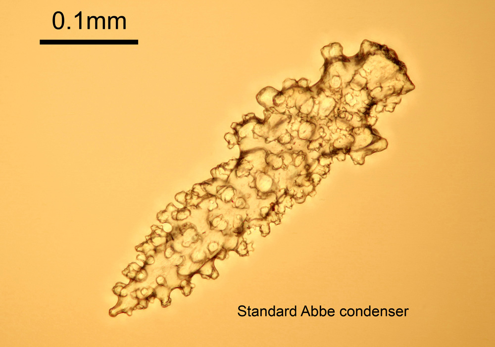
Making one of these is all well and good, but if it cannot illuminate a sample it really is not going to be a good condenser. As a quick test I imaged a sample slide of Gorgonian sea fan spicules (from Diatom Lab). These guys make high quality microscope slides great for microscopy testing and imaging, and I’d recommend checking them out if you want slides for imaging. The objective was an Olympus 20x SPlan, and the lighting a tungsten bulb in the microscope. This is a visible light image taken with a normal camera, just to test to see if the condenser would work. The warm cast to the image comes from the tungsten bulb. Images were collected as a stack of about 15 shots and processed in Zerene stacker. UV testing will come later. Firstly one of the spicules taken using the original unmodified Abbe condenser.
Now an image where the standard Abbe condenser was replaced with just a single 8mm UV fused silica half ball lens.
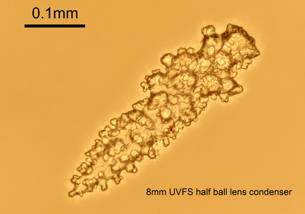
While slightly lower contrast than the standard Abbe condenser the 8mm UV fused silica half ball lens was still able to provide good lighting for an image of the spicule. Success. Also the condenser with the 8mm half ball lens is currently missing the second lens which is present in the standard one, so hopefully image quality should improve further with both lenses in place.
There are some drawbacks to using such a small lens. Sample size is limited, along with the choice of objectives. I need to use 10x or higher magnification objectives with it, but as my UVB capable objectives are 10x and above this is not a problem. The light leaving the half ball lens is highly convergent, so condenser position is crucial to getting good lighting. How this will work in UV remains to be seen as focal length will be different to that in visible light and may leave me with slightly less working distance to play with. The image with the half ball lens was slightly darker than with the standard condenser leading to longer image acquisition times (approximately one stop difference).
Where does this leave me? The conversion of a microscope to being able to do UVB imaging is a complex job, certainly more complex than I originally thought it was going to be. As such it takes time and testing. Modelling of the optical properties of the lenses has proved useful, and testing so far is looking good. I’ve been able to modify an existing condenser to install a lens which has great UV transmission characteristics and use it to create good quality microscope images. More work to be done for sure, but the UV BHB is coming along, and I am now a step closer to completion. If you want to know more about this or any other aspect of my work, you can reach me here.
Addendum – after writing this article, I’ve been able to source some larger diameter half ball UV lenses (12mm as opposed to 8mm) and they have been sourced for future testing.