
As I write this it is the the last day of what for most has been a ‘character building’ year, and I shall start today’s post with a little question – As scientists, what is it that drives us to do the things we do? See, nothing to serious, and with that slight philosophical diversion, let’s dive into the subject of this post.
With UV imaging, things aren’t always what they seem. Equipment designed for UV work could be only for certain wavelengths for instance – normal glasses can still be used for UVA imaging work, while materials such as quartz and calcium fluoride are needed for shorter wavelength UVB work, as normal glass would just absorb the light. Some microscope objectives are described as ‘UV objectives’ but are not meant for imaging in the UV, rather they have low fluorescence and are used for visible light fluorescence imaging after illuminating the sample with UV. With older equipment, it becomes hard to try and find original source information about it as it often doesn’t exist digitally, so there is little alternative to hands-on testing to try and determine if something is suitable for a specific application.
In my searches for UV imaging kit, I came across a microscope condenser called a ‘Tiyoda UV 1.2-1.4 darkfield condenser’. This piqued my interest as it sounded as though it was a dedicated UV darkfield condenser, and got me wondering whether it was made of quartz or other exotic materials. Problem was, there wasn’t any info out there on the transmission properties of it. I saw a couple for sale, for rather large amounts of money (hundreds of GBP), which was too much to invest just to answer a question. Eventually I found one for sale here in the UK which cost a lot less, but was best described as a ‘fixer-upper’. So I bought it and here it is.

The condenser came in a mount for a Reichert microscope (which I don’t have) but my main interest was to assess its UV transmission properties. Main problem when it arrived, was that the coating around the central part of the condenser was damaged, as shown below.
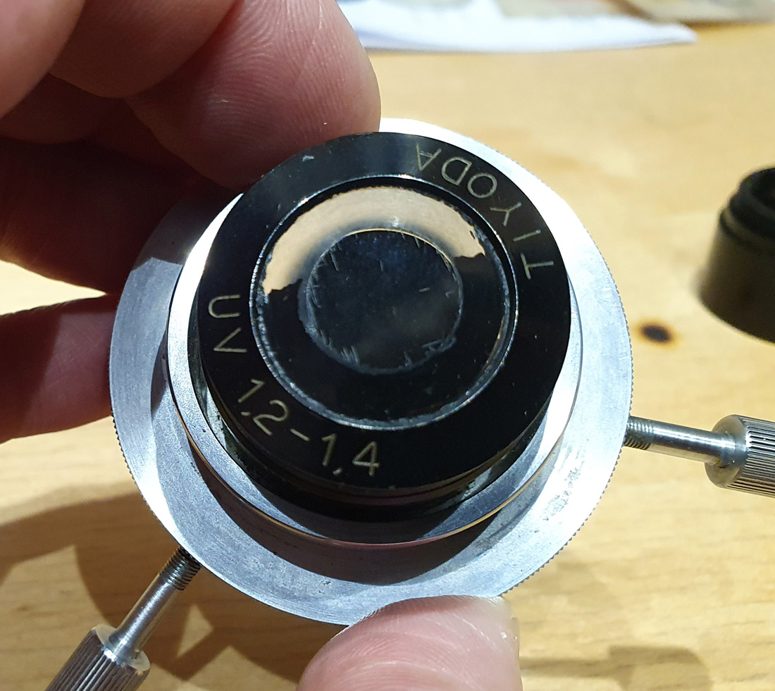
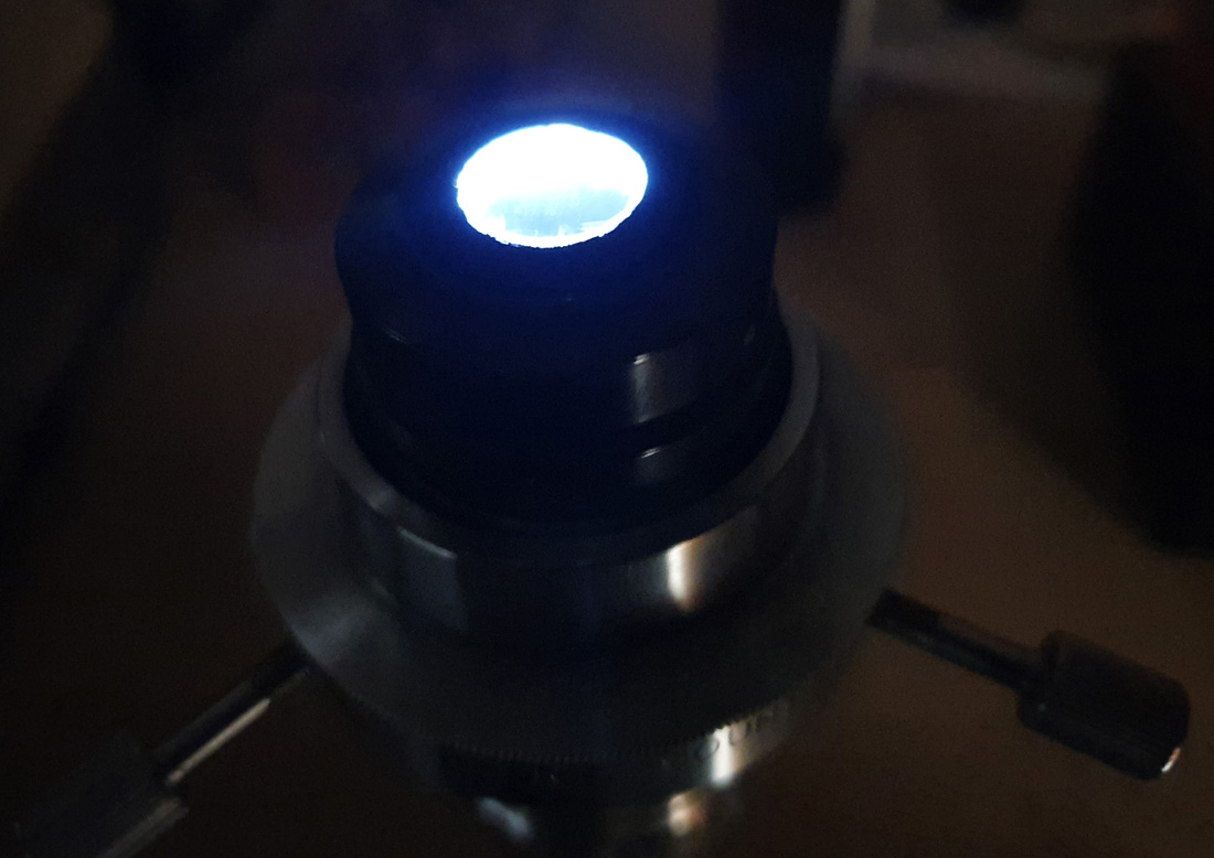
The black paint should be present in a ring around the central part of the condenser, and on this copy it was missing on about half of it. The construction of these things is quite amazing and goes back a long way. They are known as ‘cardioid condensers’ and use a specially shaped mirror to project a cone of light onto the subject. Shining a torch through this one from below produces the following.
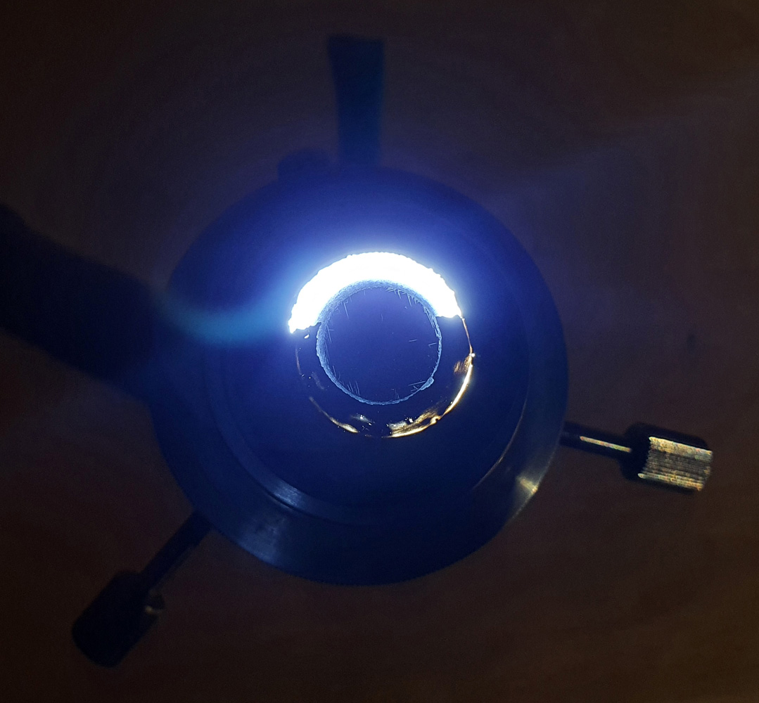
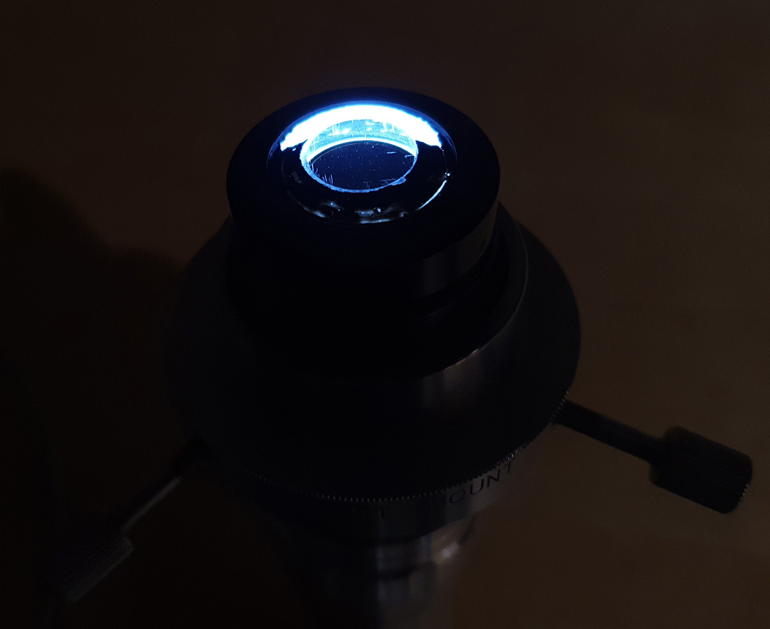
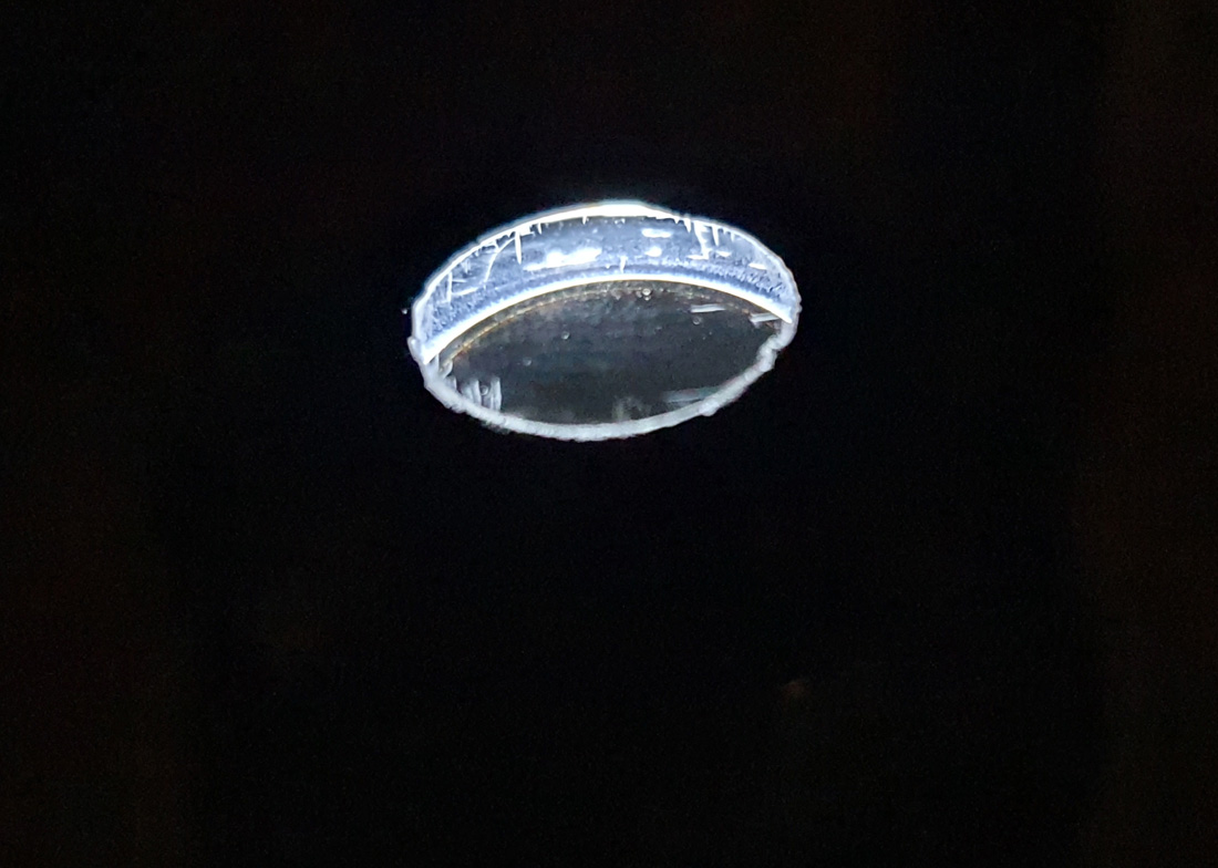
In the image above, the black ring around the central disk should be blocking all the light from below, and it’s pretty obviously damaged. The central disk is actually transparent, and this can be seen more easily if viewed from the side with the torch still on. This is what would sit just below the sample on the microscope stage.
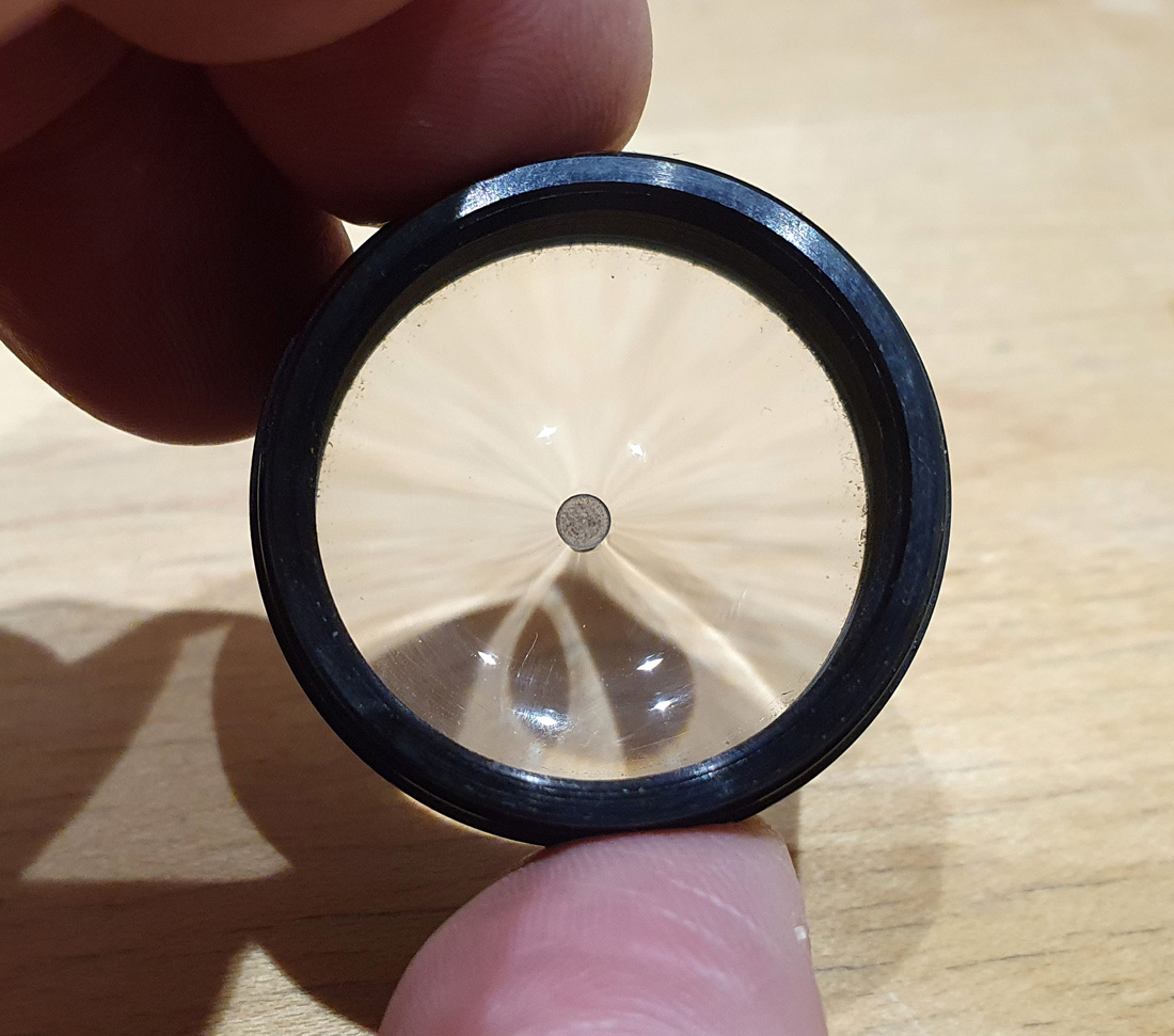
The unit consists of two main parts – the main top piece, in and above the Reichert mount, and then a screw-on lens underneath which is marked with the name ‘Super, Wide PAT. PEND.’, as shown below.
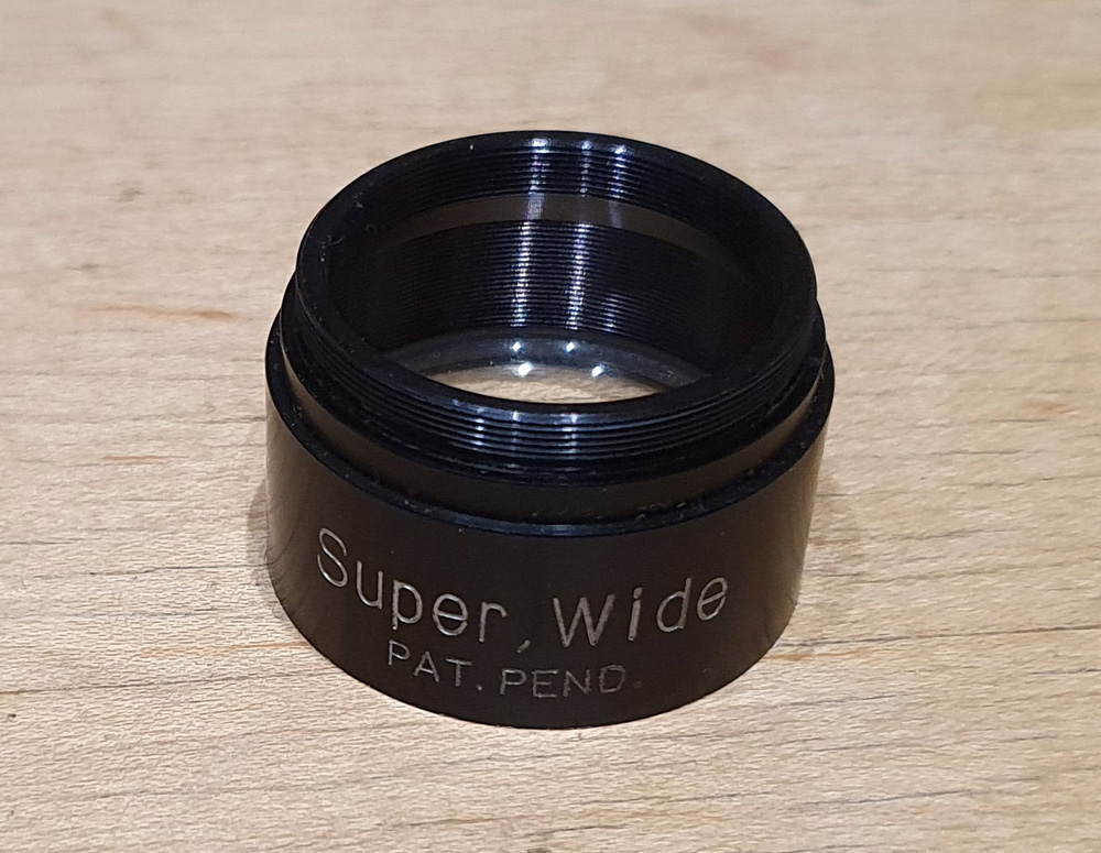
The view through this lens is pretty trippy, and it has a dark spot in the centre. It also looks very, very delicate.
This lens actually creates a circular ring of light from a point source as can be seen below, as it projects the image of my ceiling lights onto the desk.
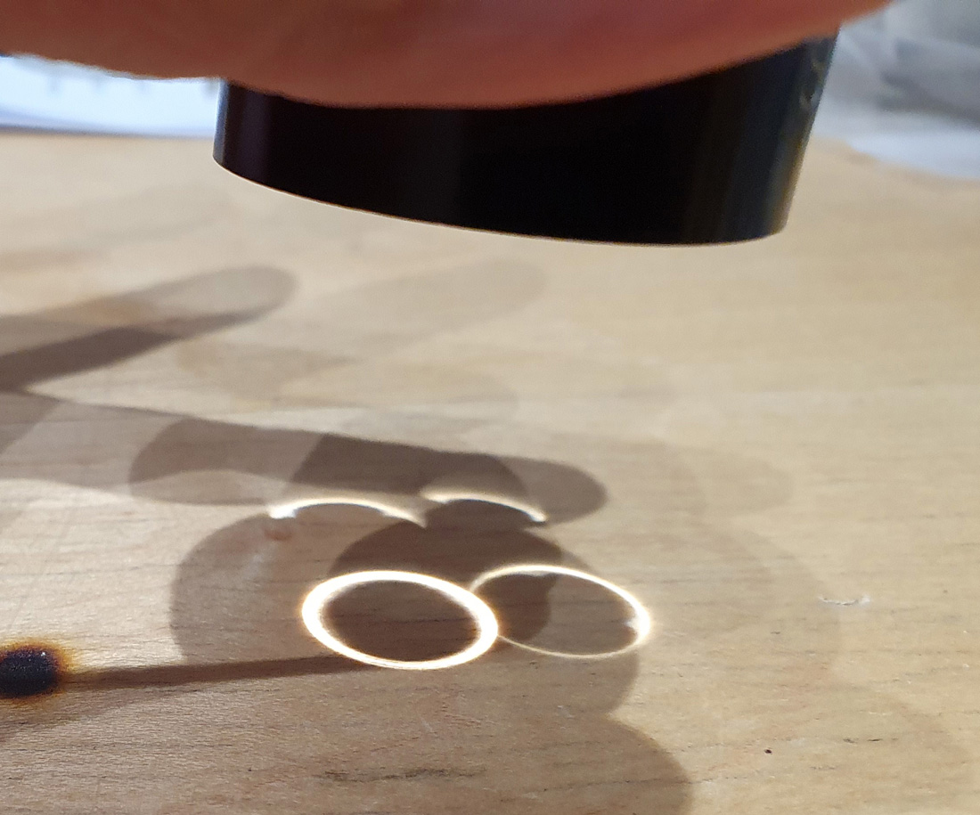
In use, this ring of light is then projected into the main body of the condenser and reflects off the mirror towards the front of the condenser. A very clever design minimizing the amount of light which would otherwise be lost.
The damage to the top of the condenser was actually a blessing as well as a problem, as it allowed me to measure the transmission straight through, so I can see whether the components were attenuating the UV. Measuring the transmission of the individual parts and complete condenser gave me the following.
Now there is a lot going on in the graph above, so I shall explain. The red line is the transmission through the Super Wide Pat Pend lens by itself. This actually shows good transmission down to about 300nm, which suggests it is a thin layer of conventional glass, rather than something unusual like quartz. The green line is the transmission through the top part of the condenser with the damaged black paint. Measured transmission is very low here, as even with the damage the light still has to bounce off mirrors and through a small hole to get to the detector, which attenuates the total signal. When the two parts of the condenser are recombined, and transmission measured, we get the blue line. Now the incoming light is focused by the Super Wide Pat Pend lens, onto the mirrors and out of the top of the condenser. As can be seen the overall transmission drops from 400nm down to about 320nm, below which it is essentially blocking the light. Note that absolute transmission of the condenser would be higher than this as the diameter of the beam of light I use for my tests is relatively large, and some light is lost by not being able to pass through the small optics of the condenser. The key thing to note is the drop in transmission at the short wavelength end. The Tiyoda UV 1.2-1.4 would therefore be good for the longer wavelength UV down to around 320-330nm, but not good below that as it would prevent the light from transmitting.
OK, so I have a damaged condenser which does not have short wavelength UV capability. What next? First step was to repair the damaged paint, and I did this using Semple Black 3.0 paint which as I have shown in other applications has great light blocking properties. After painting, the condenser looked like this.

Shining the torch through it now, and the light is only coming from the central disk.
If I turn down the exposure on the camera, and capture the torch through the condenser again, I get the following.
Basically the only light now getting through the condenser is coming through the central circular opening, as it should be. However it is pretty obvious now that there are some major scratches in the glass of the circular opening especially close to the edges. This condenser has had a hard life….
Where does this work leave me? I have a condenser in a mount which does not fit any of my microscopes. Even if the mount was modified, the diameter of the condenser means that my microscope stage would need modifying to make it fit. The condenser does not have the great UV transmission I was hoping for (although it will still be good for UVA work). The one I have was damaged, and while I have given it a new coat of paint to cosmetically repair it, I have no doubt that a few uses with immersion oil and that paint would come straight off.
So after all this, what was the point of this exercise? Looking around online I was unable to find anything definitive about the transmission of light through a Tiyoda UV 1.2-1.4 condenser. By buying one myself I was able to test it, and fill a gap in the knowledge base about these old pieces of equipment. It answered a question that was relevant to my research, and has allowed me to definitively say how it works, and where it can and cannot be used. And now I write up and share my experience, so that anyone else who may be wondering this, perhaps as part of their work, has something to refer to.
At the beginning of this post I asked a simple question – As scientists, what is it that drives us to do the things we do? Motivations for the work we can do take many forms. Money – sure, we have to make a living and some questions need answering to push projects forward. To push our own knowledge forward – absolutely. To fill a gap in the knowledge that wasn’t there and share what you know, enabling the work of others in your field to move forward as well as your own. Now there’s a nice thought as we move from what for many has been a difficult year, into one which hopefully will be a better one.
If you’ve made it this far, and would like to know more about this or any other aspect of my work, I can be reached here. Happy New Year everyone.