
When doing normal visible light photography, the question of whether the wavelengths you’re interested in capturing can even reach the camera, tends not to come up. Lenses are transparent to visible light, and our eyes and camera sensors are sensitive to it, so we can see just what we are going to be imaging. Simple. However with UV photography that is not always the case. Normal camera lenses block varying amounts of UV and if you want to image the UVB region, you need to delve into the realm of dedicated UV optics without normal glass. Even with those considerations, with UV photography once you have a suitable lens and filter, and a modified camera you are good to go. The concept of doing UV microscopy though, takes the things you need to consider for photography and amps everything up to 11. Today I’ll bring some of the work that I’ve been doing to build a UV microscope together and see what I have still got to do.
The optical train for a microscope is quite complex. In my microscope, starting with the light source, the light then goes through between 1 and 5 lenses, and bounces off a mirror, all within the body of the scope before going through the condenser. Then we have the slide and coverslip with the sample. After that we have the objective lens. Above the objective lens we have the head with the eyepieces, which also contains the photoeyepiece. And it is only all of this that we have the camera. Some of these I have discussed before, and are linked in the description above. I’ll now go through some more recent work looking at whether the internal lenses, mirrors and windows within the microscope are suitable for UV, and if not how to address that.
Within the body of my BHB microscope there are a set of lenses and a mirror that the incoming light has to traverse before it even reaches the condenser. These are to focus and direct the light so it can reach the sample with enough intensity. 3 of the lenses aren’t absolutely necessary for the UV imaging, as the xenon and mercury xenon lamps I have have some degree of internal focusing. However this still leaves 2 lenses, and mirror which are necessary. The two lenses can be seen in the image below.
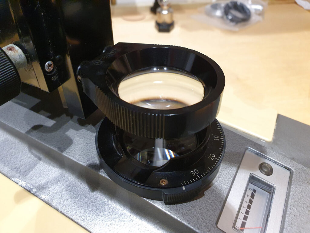
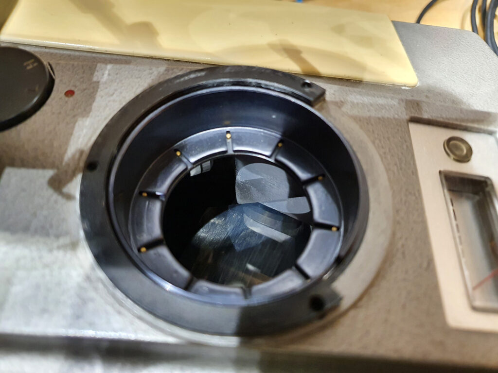
The top lens above is the Auxiliary lens, and this isn’t always needed depending on the magnification you are using. Below that with the numbered scale is the Field Iris lens. Below the Field Iris is a mirror which bounces the light from horizontal to vertical. With the Field Iris lens removed, you can just about see the mirror underneath.
In order for the microscope to be usable for UV imaging, the lenses need to be able to transmit the UV, and mirror needs to be able to reflect it. I removed both lenses and measured their UV transmission using my lens transmission testing rig, and got the following.
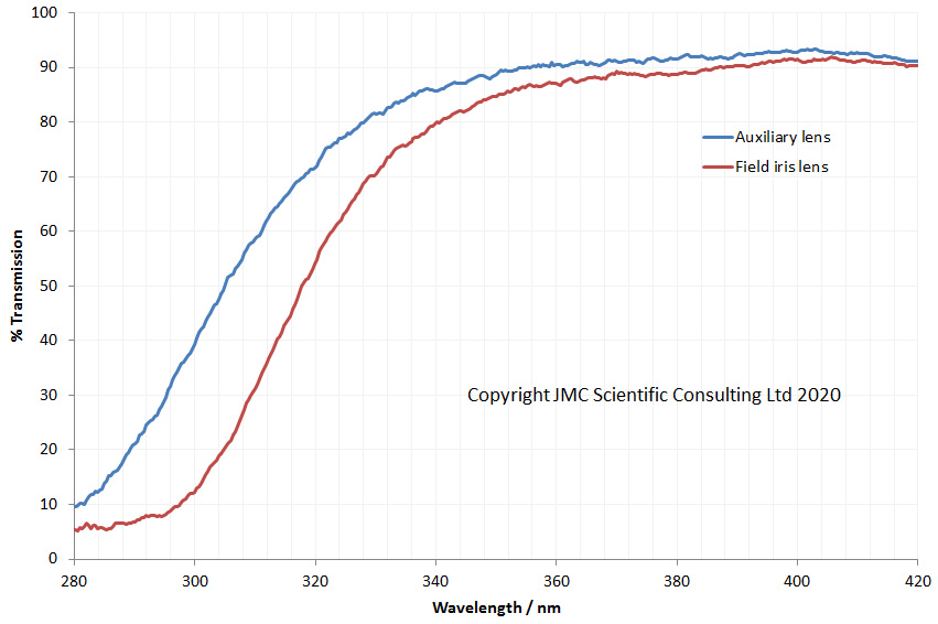
Both lenses looks like they’d be OK for 365nm imaging, but at the shorter UV wavelengths the transmission drops quickly. This makes sense as they are glass lenses, and normal glass absorbs UVB. So they’d be no good for UVB imaging. Determining whether the mirror would be suitable for UVB was a bit more problematic. I do not have a setup for accurately measuring specular reflection from shiny surfaces, and I didn’t want to remove the mirror unless absolutely necessary, as they can be annoying to realign. This meant trying to test it in-situ. To do this I used a Xe lamp. I measured the spectrum of the lamp by itself. Then shone the lamp off the mirror and measured the spectra again. I then normalised these for max irradiance (which occurred at about 400nm) and calculated how much light was reflected from the mirror vs the light output from the lamp alone for between 250nm and 410nm, and got the following.
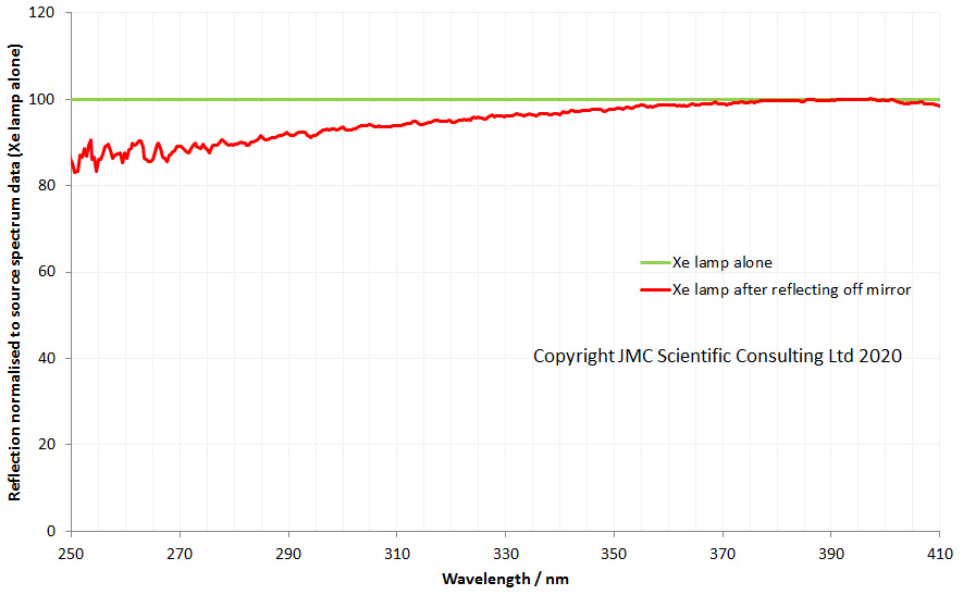
The mirror reflection shows no major dips down to 250nm indicating good reflection in the UVB. This is not a perfect test, as I am assuming that 100% of the light is reflected at 400nm. However it is good enough for seeing whether there are any big dips in the reflection spectra. The next job was determining focal lengths for the lenses. The Auxillary lens was 40mm diameter, planoconvex and about 7cm focal length. The Field Iris lens was 40mm diameter, biconvex and about 13.5cm focal length. For replacement UV suitable lenses, I’ve gone through Laser2000, who have good range of lenses in different sizes and focal lengths and went with a 7cm planoconvex, and 15cm biconvex. For the biconvex the available focal lengths were 12cm and 15cm, however as the wavelength decreases the focal length does too for these simple lenses, so the 15cm is nearer to the original in the UV. These lenses should enable good transmission of UVB to the condenser. Will this prove to be the right choice – I shall see when then lenses arrive. Watch this space…
The next thing to consider what happens to the light between the objective lens and the camera. On the Olympus BHB there is a binocular head which fits on top of the microscope which allows the user to view the sample. This can also be fitted with a third vertical tube (making it a trinocular) which enables a camera to be fitted. The head however also has some optics in it – a thick window at the base, and a beamsplitting prism to enable the light to be split between the eyepieces and the photoeyepiece for the camera. Of course, every piece of the glass in the optical train has to be assessed for suitability when thinking about UV imaging. How do these components impact UV transmission? Thankfully the BHB head is straight forward to take apart (I love old mechanical designs). Doing so reveals a thick window at the base of the head and the prism beamsplitter assembly, as shown below.
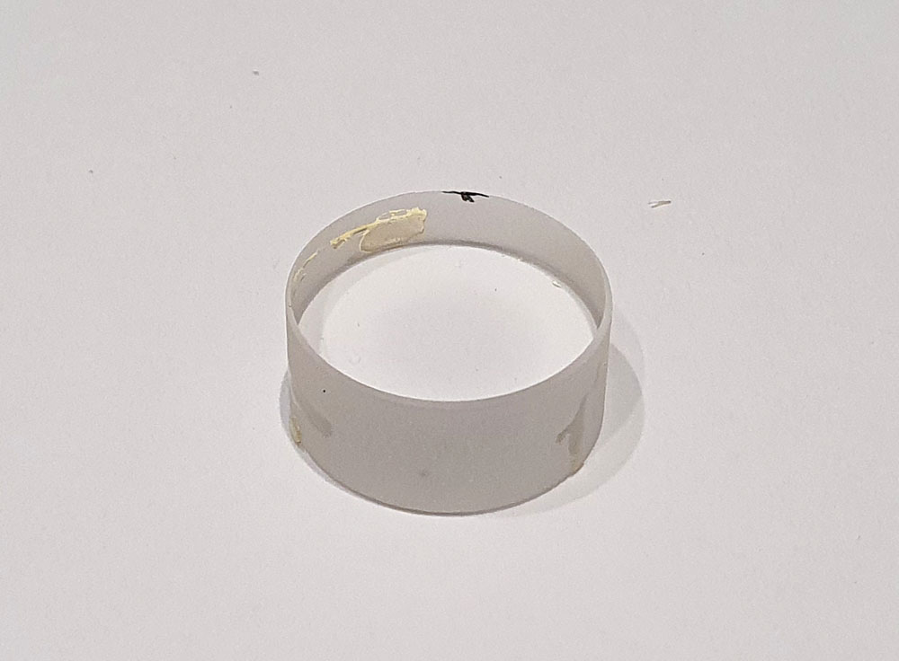
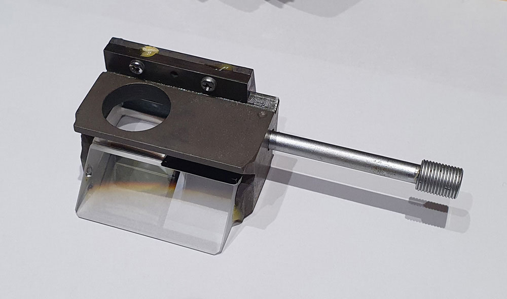
The window is thick, very thick. The size is 20.9mm diameter and 9.9mm thick, but it does look to just be a window and not a lens. It also looks to be a simple single element. The beamsplitter is more complicated. In the position shown in the image above the light is sent to both the viewing eyepieces, and the photoeyepiece. While not obvious in the photo, this requires two prisms – one on top of the each other – and there is a glued interface as well, making it quite complicated. There is no path to the photoeyepiece without going through this prism arrangement. The transmission spectra for these two components are shown below.
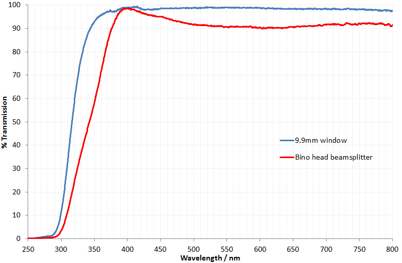
Both the window and the beamsplitter show good transmission at 365nm, but the transmission does drop quickly as the wavelength gets smaller, and is essentially zero by 300nm. For imaging at and below 300nm both of these will block all the UV and be opaque. This could be a tricky one to fix – if I want to use the head for UVB, so I can view the sample before taking the photo, I’ll need to figure out a way of getting the UV through these components. I can just use a vertical monocular tube for the photos, as that has no optics in it, so there is another approach, but I’d like to keep the optical eyepieces if possible. More thought needed here, especially with regards to making the use of eyepieces with UV light sources safe…… After more thought (and more coffee) I shall take some measurements and source suitable components to test.
Just over 6 months ago now I started my journey into microscopy, and it has so far proved fascinating and challenging in equal measures. Setting myself the challenge of making a UV microscope able to be used down below 300nm have really made my life difficult. But then science is often difficult, and a challenge is not something that should be shied away from. Being able to image in UVB and UVA will be useful for my sunscreen research and for imaging sunscreen formulation structure. If I were to try and have a UVB suitable microscope built, I doubt I’d get much if any change from 100,000USD so until I win the lottery is a bit outside my R&D budget. In fact a couple of the objective lenses alone if bought new would cost more than I have spent on my entire project to date, so a self build is the only option. I’m not there yet, but am gradually working through the issues and will update as and when I have more results. If you’re interested in this or any other aspect of my work, I can be reached here.