Some experiments are complex to setup but easy to do, others are in theory simple to attempt but in practice quite time consuming to carry out. This little experiment was not particularly hard to do, but took quite a lot of time to setup and get the images and process the data. Quite a neat result though, so I thought it was worth sharing.
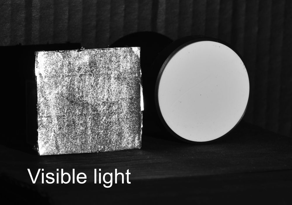
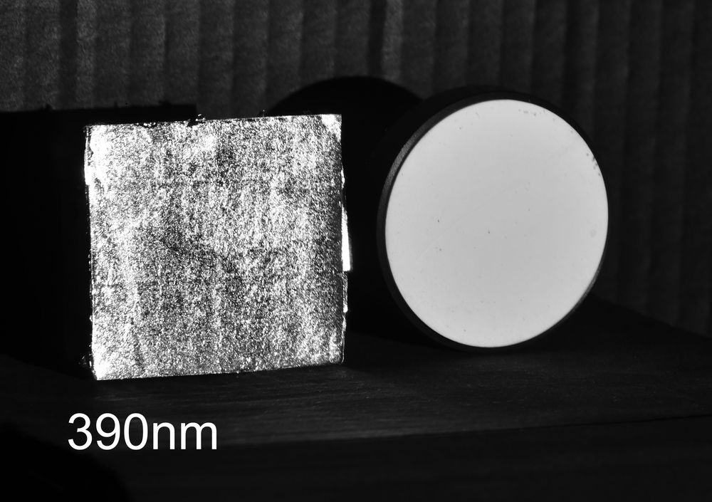
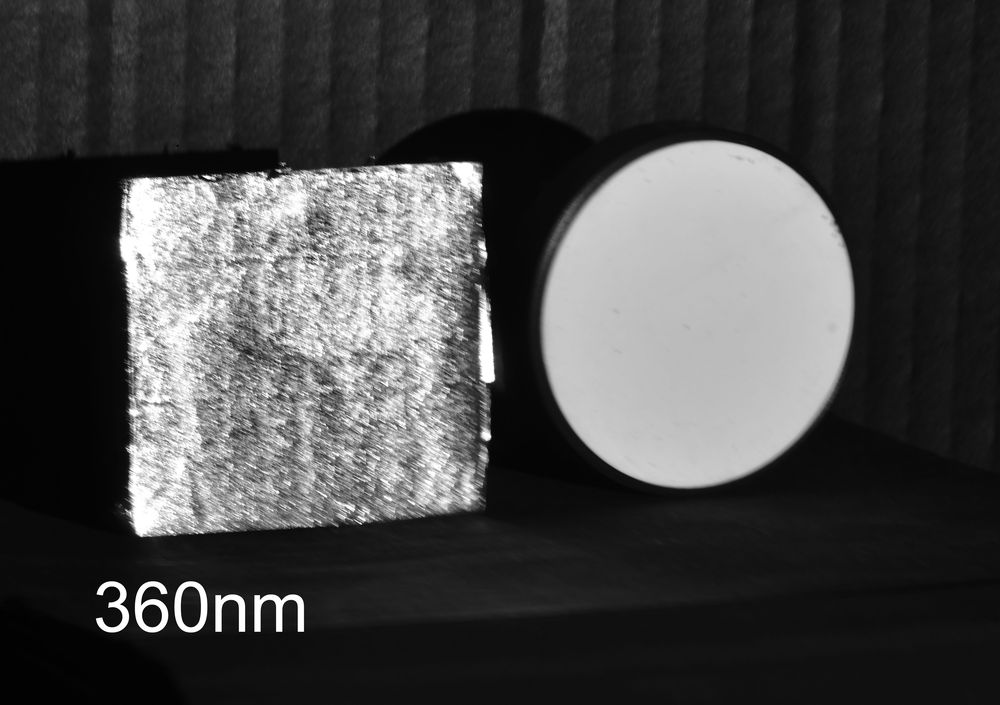
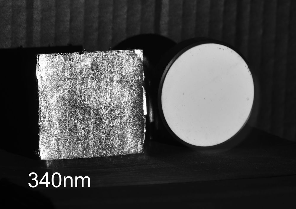
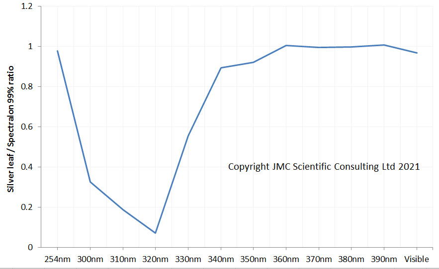
This came about after a discussion on the Ultraviolet Photography forum, about the behaviour of the metal silver in the ultraviolet. Silver should have a strong dip in its reflection curve at around 320nm, as shown here, and it got me wondering whether I could image that with my UV camera setup. Not having loads of silver laying around the house I ordered a couple of sheets of edible silver leaf which is used in cooking, and mounted some on a piece of cardboard.
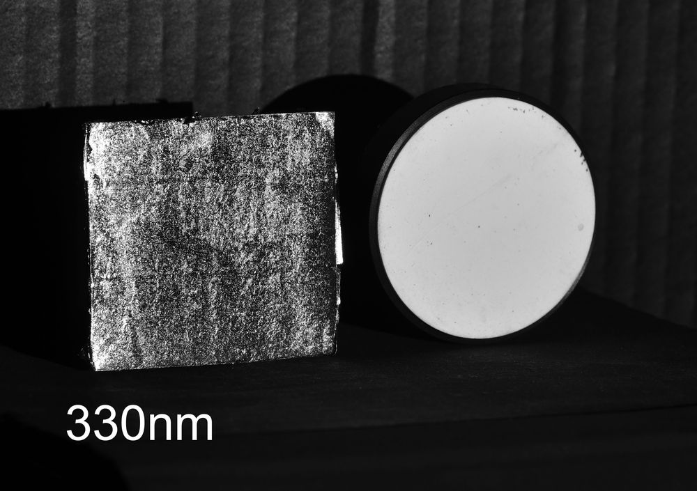
Imaging wise, I placed the sample in a box painted with Semple Black 3.0 paint to keep the reflections down. I also included a 99% Spectralon diffuse reflectance standard along with it. This was so that I could balance the exposures at different wavelengths and loo for differences in how the silver appeared. Camera was a monochrome converted Nikon d850 from MaxMax, lens was a 105mm UV Rayfact. Filters were a mix of Baader UV/IR for visible light, Thorlabs and Edmund Optics bandpass ones for 390nm to 300nm (along with a Hoya U-340 4mm for the 300nm image as the bandpass filter leaked a bit), and a 254nm bandpass filter from a forensics camera. Light source was a Hamamatsu LC8 200w xenon lamp which I used down to 300nm and a UVP 254nm filter lamp for 254nm. You can see now why it was time consuming.
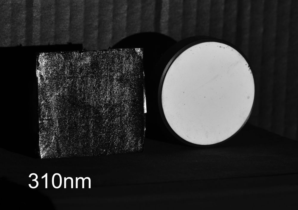
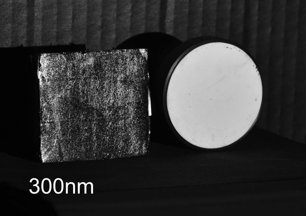
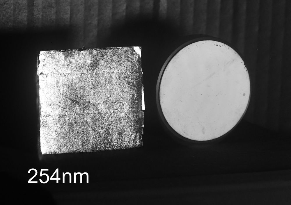
The images were as follows.
The images did indeed show a very sharp drop in reflectance of the silver at around 320nm. Yay, the images back up the data from the reflectance graph. Good to know the edible silver leaf is indeed silver.
Including the Spectralon standard allowed me to compare the channel response from the silver with that of the Spectralon, and plotting that gave the following.
Plotting out the channel response does indeed show the strong dip in reflectance at 320nm and matched the literature data well down to 300nm. At 254nm though the match is not so good, and I am not 100% sure as to why that is. I believe that Spectralon reflectance starts to drop around 250nm, and I know from imaging at 254nm before that any organic material would be highly absorbing at that wavelength. As a result the 254nm image of Spectralon may be darker than it should be as my sample certainly could do with a clean. If this is darker than expected then it would make the silver seem more reflective than it is. It should also be stressed that at 254nm camera sensitivity is extremely low so of all the data points this is the one I am least confident in. More work needed on that from me to understand it better….
Why bother doing this you may ask, why use a camera in this way? Well, that lovely antique you are interested in buying that is supposedly silver, do you really know that it is? This type of technique can be used to check what materials actually are, and can sometimes be simpler to implement than x-ray methods and less damaging to the samples. However my main interest was curiosity – could I use a camera to see the behaviour of silver in the UV trying something to see what will happen. After all, a lot of research starts with a a curious scientist. Thanks for reading, and if you’d like to know more about this or my other work, you can reach me here.
Had a great time yesterday giving a talk to the Royal Photographic Society Imaging Science Group about imaging skin with ultraviolet, visible and infrared light.
Active for over 100 years, you can read more about the Imaging Science Group and their activities here, as well as finding out about their upcoming talks for October and November. My talk covered cross polarization, UV and IR photography of skin as well as applications of UV fluorescence in dermatology. The talk was recorded, and can be viewed on the RPS Imaging Science Group website, along with the other talk from the evening on UV reflected and fluorescence imaging of plants by my fellow speaker Adrian Davies, if you’d like to view it.
Thanks again to the folks of the Imaging Science Group for inviting me to talk to them.
Had a great time today presenting about the measurement and assessment of skin erythema to the NHS Tayside Photobiology Unit, whose aim is to offer a comprehensive diagnostic, therapeutic and management service for Scottish patients with photosensitivity. Approximately 250 patients are assessed through the service each year. They are also the collaborative centre with NHS England Highly Specialist Xeroderma Pigmentosum Services based in London. The Unit additionally provides the National Cutaneous Porphyria Service, offering laboratory investigations and advice for patients with this group of diseases. They also offer an extensive range of phototherapeutic options and the Managed Clinical Network for Phototherapy in Scotland (Photonet) was developed there. Additionally they coordinate and lead the Scottish Photodynamic Therapy (PDT) Centre and are the first centre to receive Euro-PDT Centre of Excellence accreditation. For more on the work they perform, see here.
Erythema (skin redness) is a vital marker for showing the effects of UV exposure on skin. Took the team through the range of methods and approaches for assessing and quantifying erythema, along with the watch-outs and considerations that are needed.
Great to have the opportunity to offer training to the team on such an interesting area.
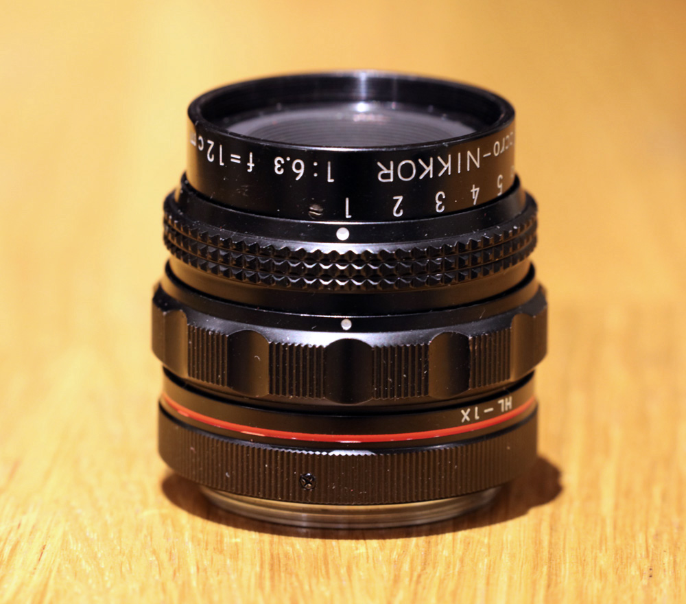
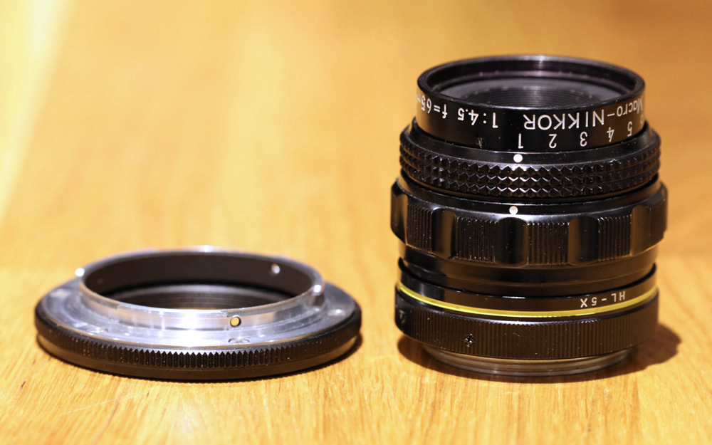
As researching the photographic imaging process is part of my work, I am lucky enough to have access to a number of amazing lenses. Today I share with you the Nikon Macro Nikkor 65 mm and 12 cm lenses. These are not to be confused with Nikons usual macro lenses (actually Nikon calls these Micro Nikkors), the Macro Nikkors were developed for the Multiphot large format photomacrography and photomicrography system. Confused yet? If so don’t worry, basically they are M39 threaded, completely manual lenses, designed for close up work with a bellows. I wont share much about their background here, as there has been plenty written already about them (for example, see here).
Why my interest in them? Well, they are great macro lenses, with a bit of a reputation among photographers, and as always I am interested in learning more about the more unusual pieces of equipment. As always I’m also interested in whether or not lenses have the potential for use with UV imaging. I was recently fortunate enough to be able to get two of the four that were made – the 65mm and 12cm ones – along with an adapter to fit them to Nikon bayonet mount for mounting on a normal camera. Here’s how they look. First the 12cm.
12cm Macro Nikkor lens
And the 65mm one along with the adapter.
65mm Macro Nikkor and Nikon bayonet adapter
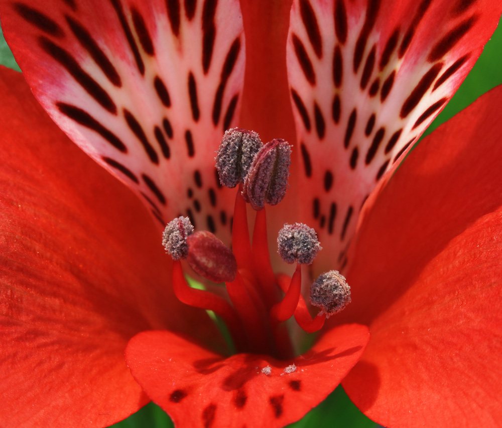
What’s their image quality like. As a quick test shot here’s a close up of a flower, taken with the 65mm one on bellows, using one of my Canon EOS 5DSR cameras and with ambient light in the room. This was pretty much the full frame, but reduced in resolution for sharing online.
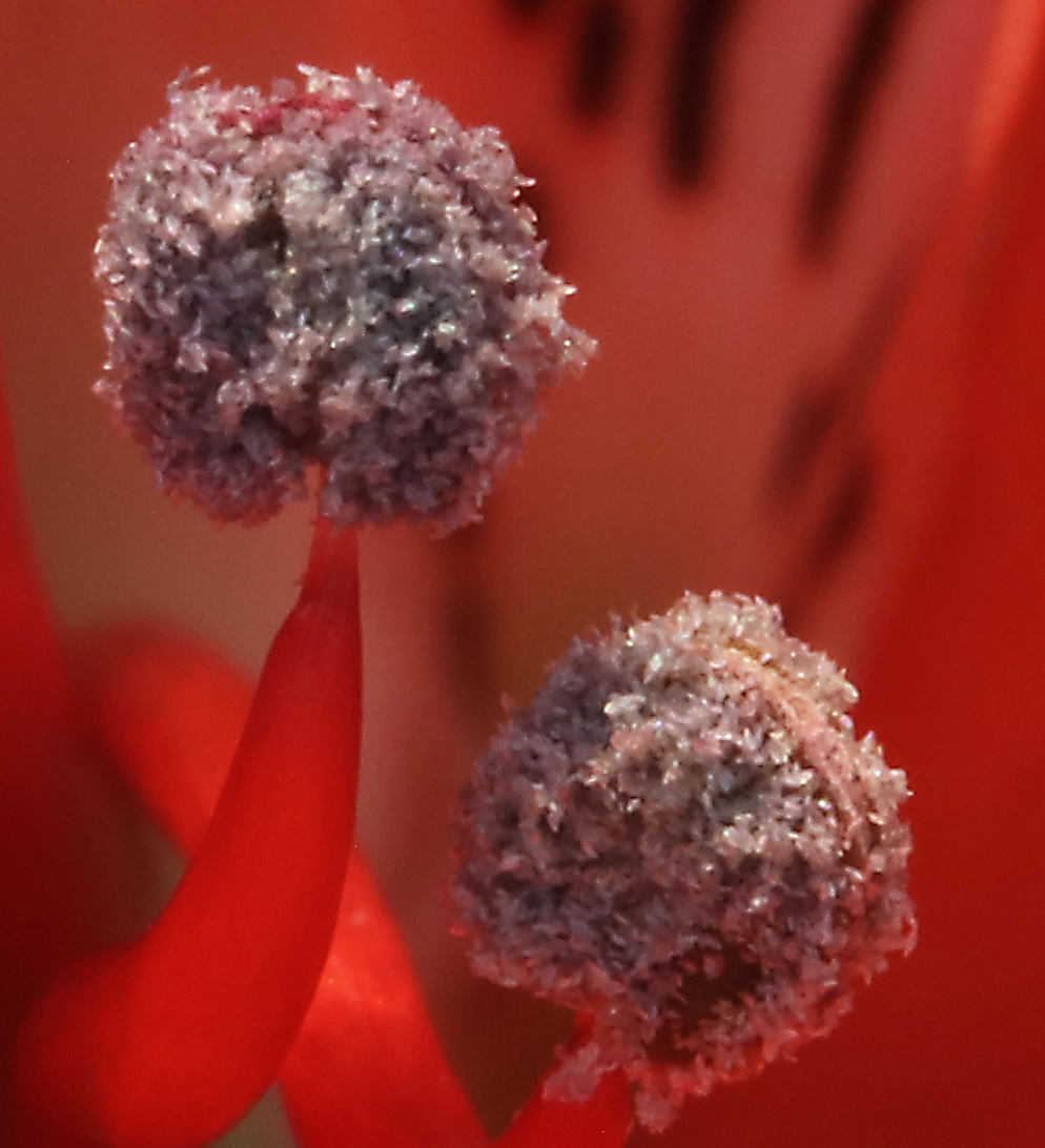
And now a crop from the original of the image above, shown at the actual pixel resolution of the image.
Given this was done with ambient light rather than flash, so the exposure time was 4 seconds, I’m quite happy with the quality it produced.
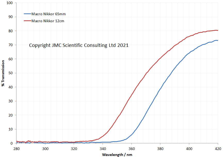
How did they look for UV transmission? As always I test my lenses with my Ocean Insight FX spectrometer for transmission between 280nm and 420nm, and here’s how they performed.
UV transmission of the Macro Nikkors
Not the best for UV transmission, although the 12cm one has more reach than the 65mm one. Not hugely surprising, given the optical coatings they have, and their overall construction. C’est la vie, although they would still be potentially useful in the 360nm to 400nm range.
Bit a brief update today, but back to work now. This cutting edge science wont do itself you know. Thanks for reading and if you would like to know more about this or other aspects of my work, you can reach me here.
As discussed here, I was recently fortunate enough to be able to spend a few days evaluating a Phase One IQ4 Achromatic camera, courtesy of Teamwork Digital Ltd here in the UK. This really interested me as it is a medium format (53.4mm x 40.0mm) back side illuminated sensor with no Bayer filter layer. Given my work imaging outside of the visible spectrum, this had a lot of potential, so I wanted to see what it could do. I wont go through all specs of the camera here, but this is prestige piece of imaging equipment and for more information about it head to the Phase One website.
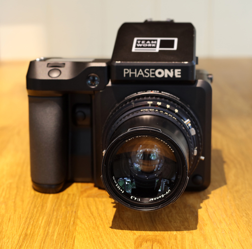
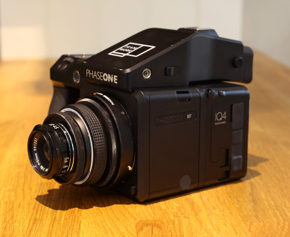
For this test I wanted to be able to see what the camera could do with a given subject looking at it from UV, through the visible to the IR, in effect across the full range of sensitivity. To do this I used a light source which produced light across that range (Bowens GM500 flash units with quartz tubes), a Zeiss UV Sonnar 105mm f4.3 lens, which I have previously mentioned here, and is a very special lens made of quartz and calcium fluoride elements rather than glass, making it suitable for deep UV work. Here’s how the lens looks mounted on the camera.
Zeiss UV Sonnar 105mm f4.3 on the Phase One camera
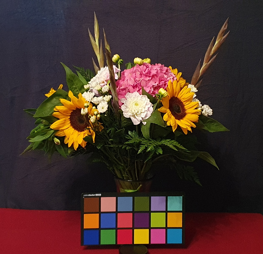
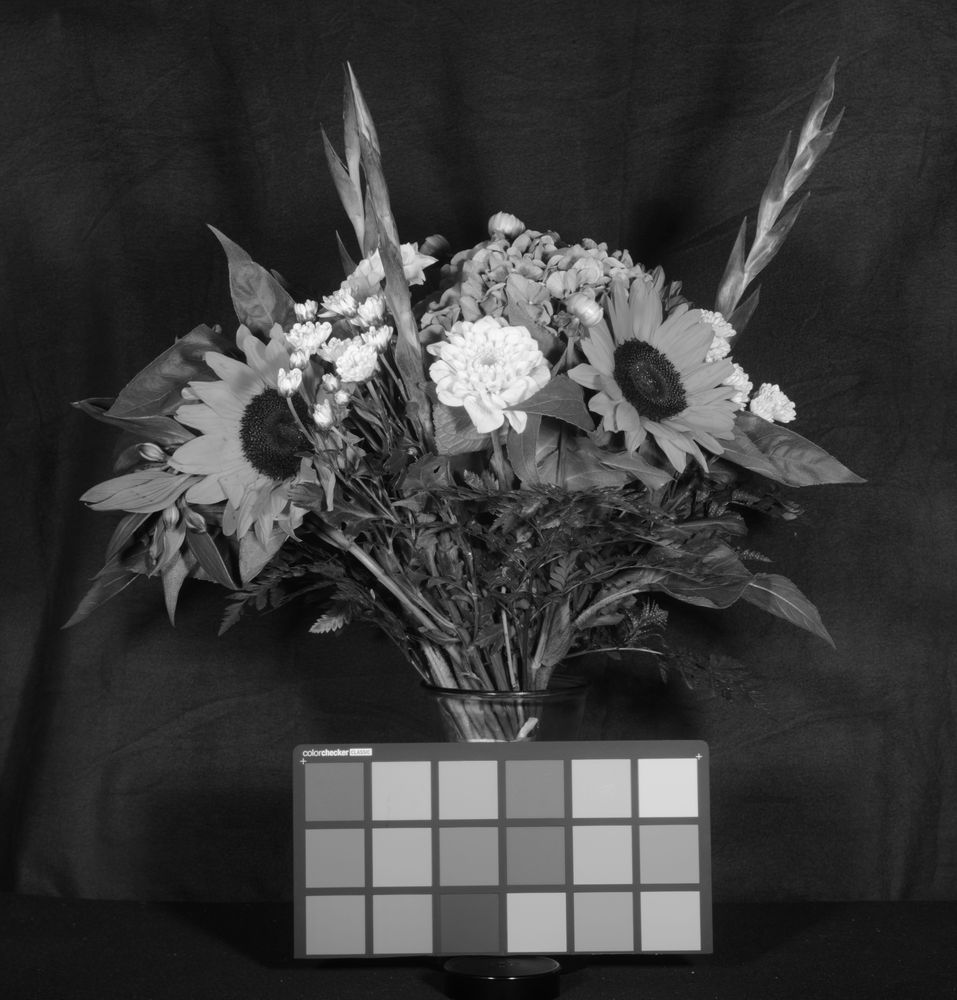
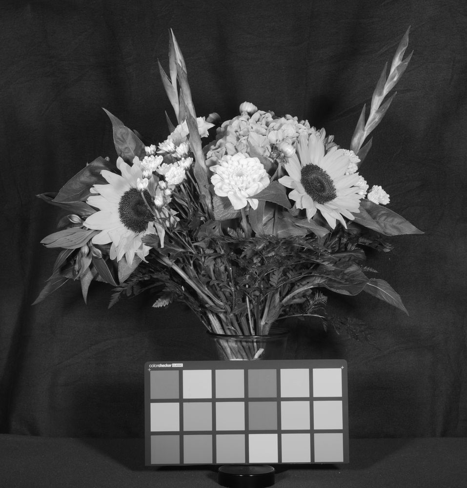
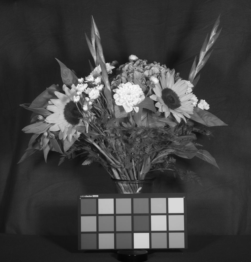
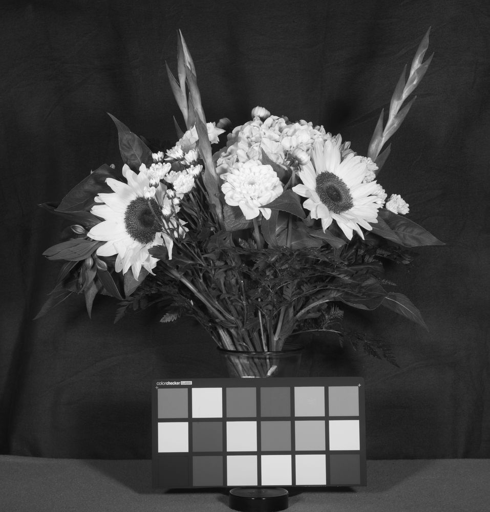
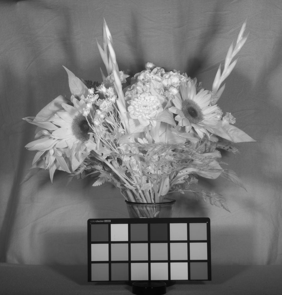
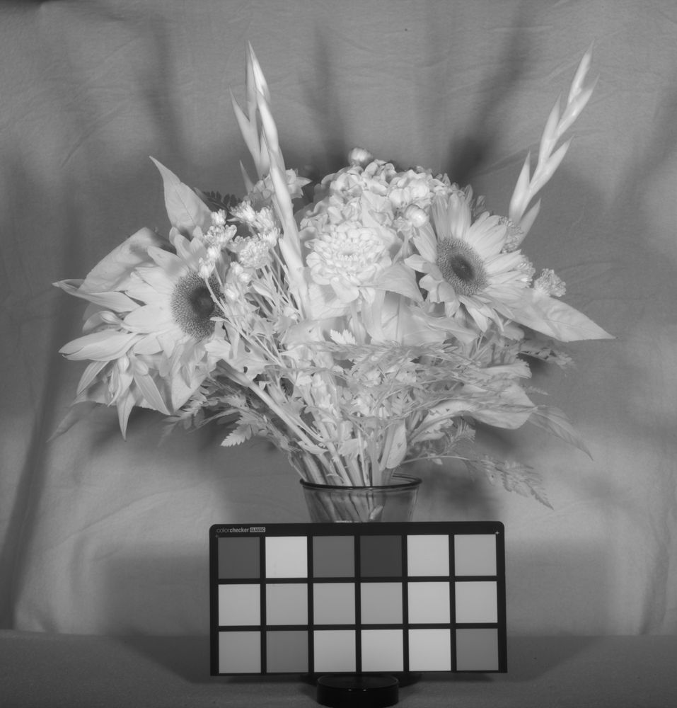
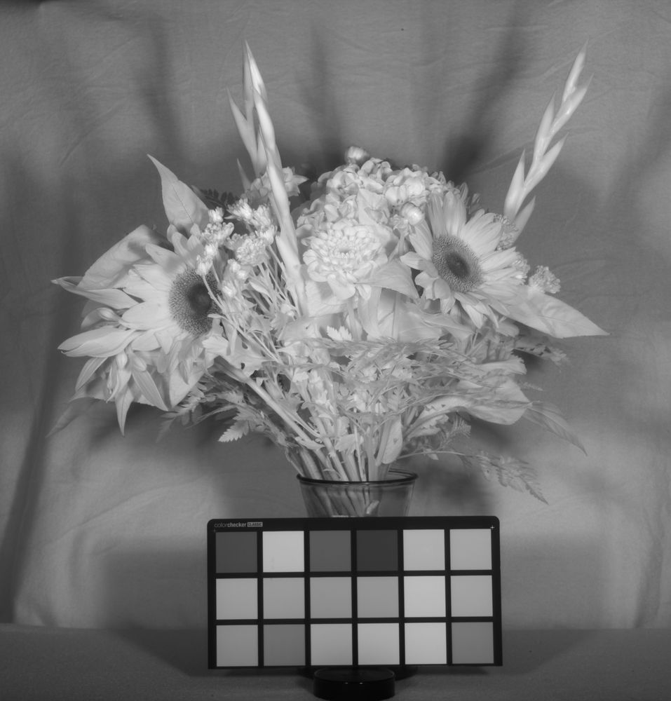
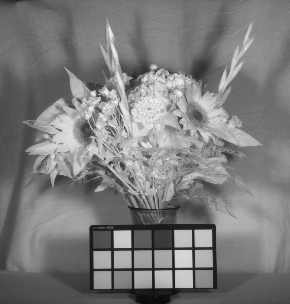
For a subject, a bunch of flowers from my local florist – Tangerine and Green, Englefield Green. I also included a Colourchecker chart, although as some of you may notice it looks a little odd. I cut the bottom row of white, grey and black tiles off to run in a spectrometer a while back, so it is now just the coloured tiles. Oh, the challenges of science. The images below firstly show the flowers in the visible spectrum (taken on a camera phone) and then in black and white from the IQ4 Achromatic from the UV through to the IR using a range of different filters which are mentioned below each image.
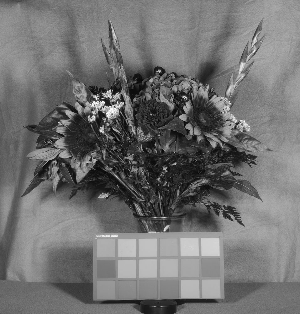
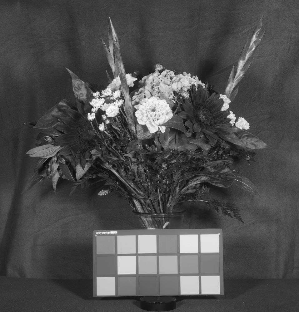
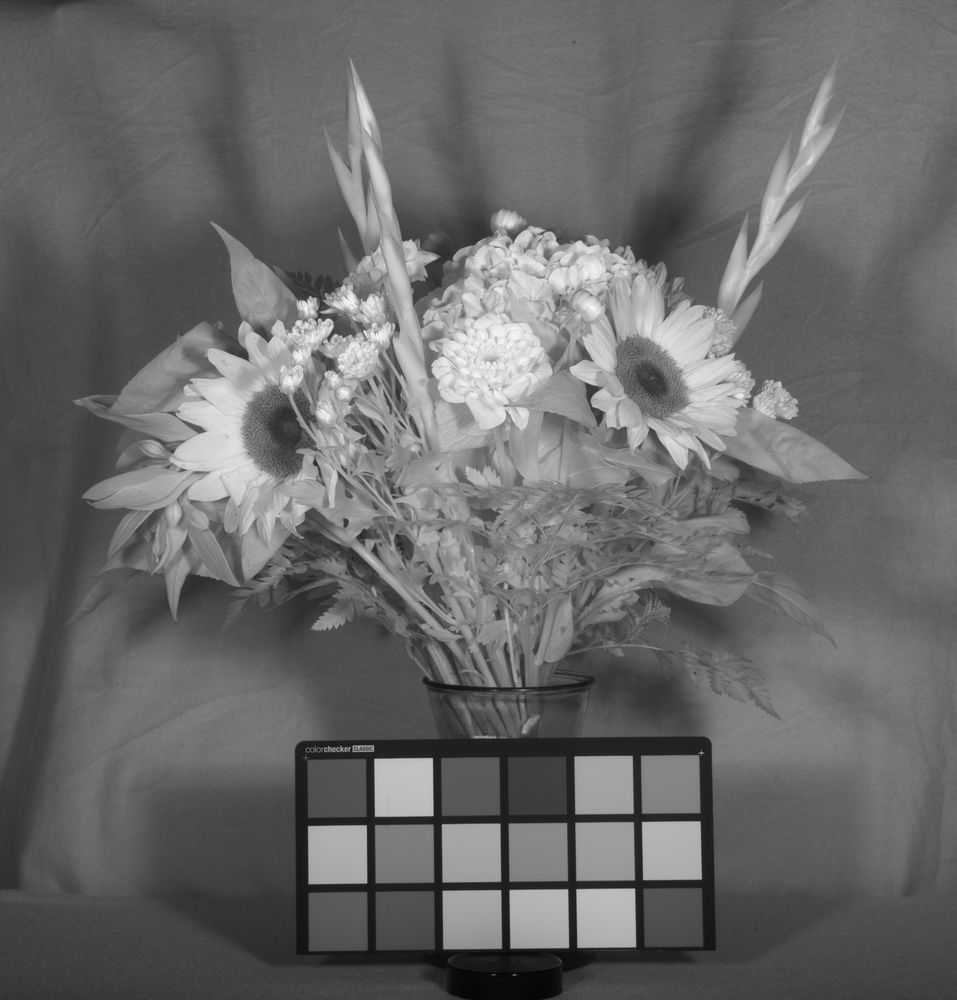
Visible light colour image taken with camera phoneUV image (Baader U filter)Digital Collodion (Schott BG18 + Schott BG25 filters)UV, blue and some IR (Schott BG25)Visible region (B+W UV/IR cut filter)Green (Hoya Green filter)Red and IR (B+W 090 red filter)Red alone (B+W 090 red filter + B+W UV/IR cut filter)IR (Heliopan 715 filter)IR (Heliopan 780 filter)IR (Heliopan 830 filter)IR (Heliopan 1000 filter)
With the images above, they have been reduced hugely in size from the original resolution for sharing on here. Also the flash settings and ISO needed changing for some of the images, especially towards the ends of the wavelength range.
Overall, the flowers demonstrated a huge change their appearance in the different wavebands. The digital collodion image (with the Schott BG18 + BG25 filters) is an interesting one. I’ve written about that filter stack before, here, and it is interesting to see how different the flowers look with it compared to both UV and the broader visible light images. As expected the flowers look fairly similar with the various different IR filters.
Again, very impressed with the Phase One IQ4 Achromatic. It was certainly able to capture images from the UV through the visible and into the IR, when used in combination with suitable lens, filters and light source. I will have more to come from my evaluation of the camera, when I look at its use for landscape photography in the visible and IR regions. Thanks for reading, and if you’d like to know more about this or other aspects of my work, you can reach me here.
I was recently fortunate enough to be able to spend a few days evaluating a Phase One IQ4 Achromatic camera back, courtesy of Teamwork Digital Ltd here in the UK. This back really interested me as it is a medium format (53.4mm x 40.0mm) back side illuminated sensor with no Bayer filter layer. Given my work imaging outside of the visible spectrum, this had a lot of potential, so I wanted to see what it could do. I wont go through all specs of the camera here, but this is prestige piece of imaging equipment and for more information about it head to the Phase One website.
Working with a sensor this large does present some challenges if you are used to cameras will full frame or APS-C sensors, chiefly that of the image circle produced by the lens you use. I have a few Hasselblad lenses designed for the old 6×6 cameras from my film camera days, but more on that in a future post. For the work I’ll be showing here I actually used an El-Nikkor 80mm f5.6 enlarger lens (old version with the chrome body), and this is shown mounted on the camera below.
Phase One IQ4 Achromatic with the El-Nikkor 80mm f5.6 enlarger lens attached
Mounting the enlarger lens was relatively straightforward – Teamwork provided me with an adapter to go from the Phase One XF body to Hasselblad, and then I had a Hasselblad to M39 adapter setup from Zörk which has a ball joint (for tilt work) and a helicoid (for focusing). A setup like this makes macro imaging nice and simple, and this older version of the El-Nikkor 80mm has good UV transmission as well.
Subject wise, I used some lovely flowers from my local florist – Tangerine and Green, Englefield Green – as I knew I could get some which would have nice UV signatures. Lighting was done using a single Bowens GM500 studio flash head with a quartz flash tube which I had custom made. Images were taken in the UV using a Baader U filter, and in visible light using a filter stack of Schott S8621 1.5mm and a 420nm longpass filter.
Firstly, a sunflower in UV.
Sunflower in UV with the Phase One IQ4 Achromatic
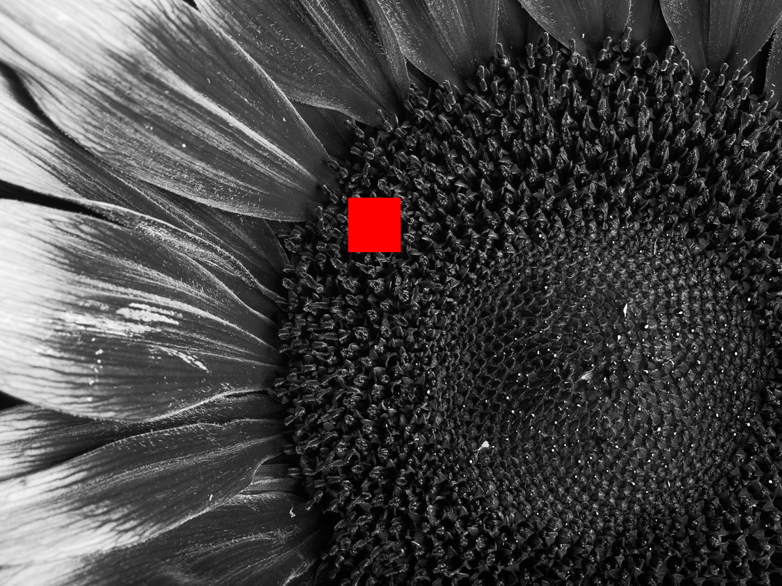
The UV sunflower image shows the expected behaviour of the dark centre to the flower, and the dark inner parts of the petals. The image above is the full frame shot captured by the camera – no cropping. Obviously the image above has been reduced in resolution for sharing here. As an example of how much information there is in one of the images produced by this IQ4 back, take a look at the two images below.
UV sunflower image with a 1000×1000 pixel region marked out
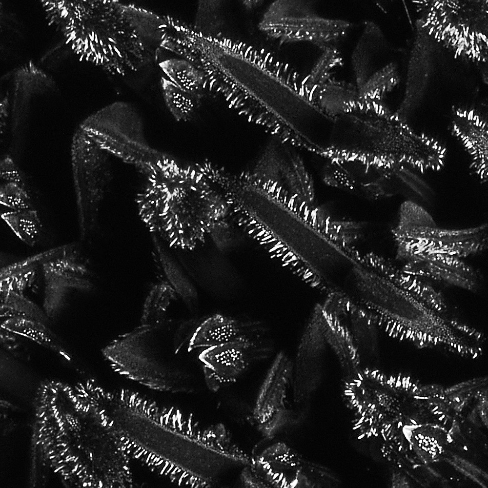
The images above shows the sunflower in UV again, this time with a red square that in the original full size photo would be 1000 x 1000 pixels. A crop showing this area in the original image resolution is shown below.
Original image resolution from the UV sunflower image
The amount of information contained within one of the images that the IQ4 back can produce is staggering. And keep in mind, I’m using an enlarger lens here, not one of the new lenses built for these cameras, so I doubt the resolution in my images is as good as what can be obtained.
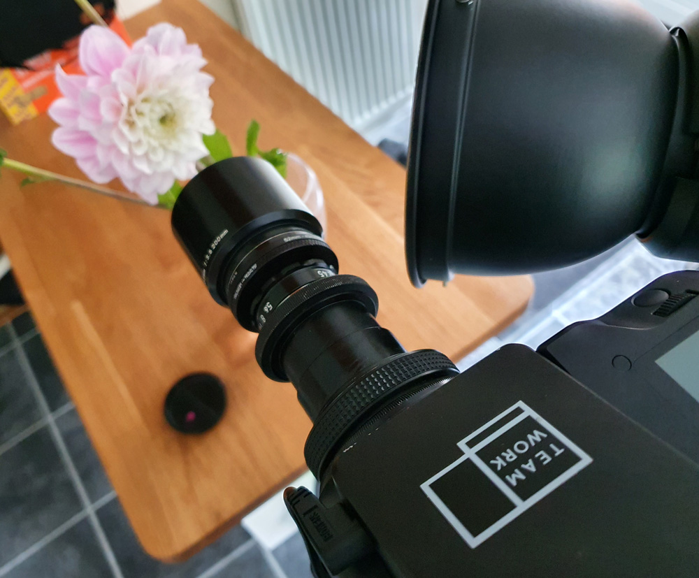
The imaging setup for the flower close-ups is shown below along with a second flower that was imaged. I’ll be honest I’m not sure what this flower is (could be a Dahlia, however that is a bit of a guess), but it looked nice, and I thought it would make an interesting subject.
Imaging setup for flower macro work
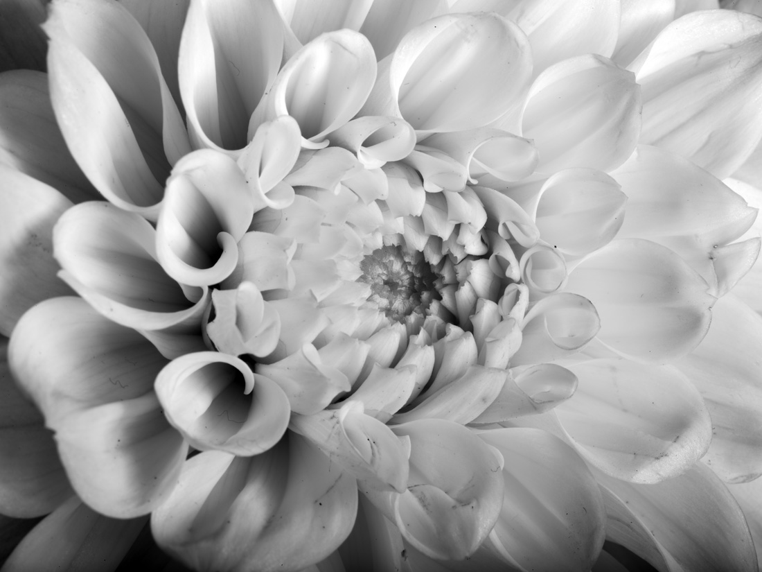
This is how the flower looked when imaged in visible light.
Flower in visible light
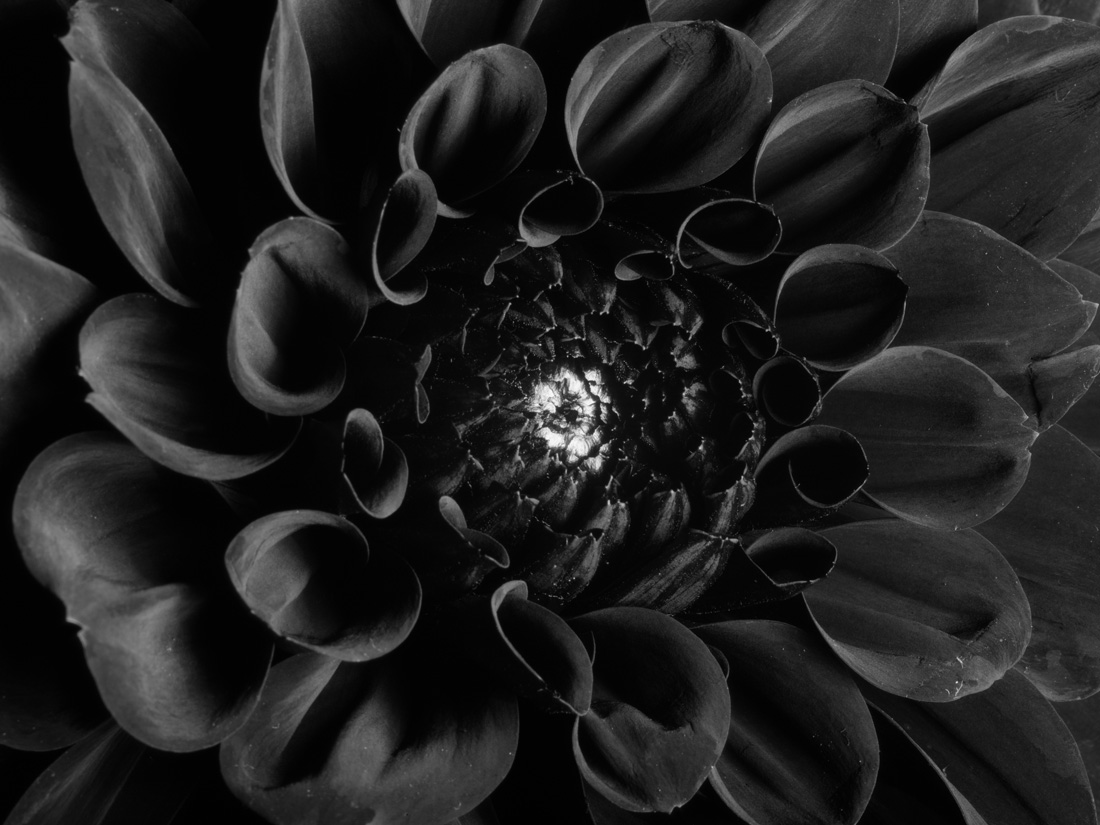
And now the same flower under UV light.
Flower in UV light
This flower looked very different under UV – it goes from being very pale in the visible spectrum to absorbing most of the UV light and looking almost black, apart from right in the centre.
Overall I was really impressed with the Phase One IQ4 Achromatic. There’s no doubting it is a premium product and it does come with a premium price tag, but the images it is capable of producing are certainly up there in terms of quality. Thanks again to the guys at Teamwork Digital Ltd for making this work possible, and to you for reading this. I will be sharing more images taken with this camera in future posts, including some Infrared ones, so check back in and see what else there is. If you’d like to know more about this or any other aspect of my work, I can be reached here.
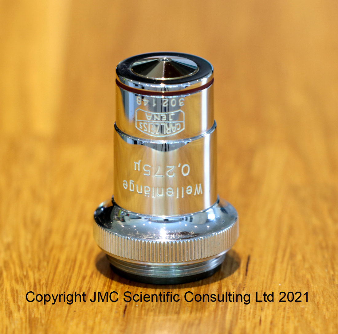
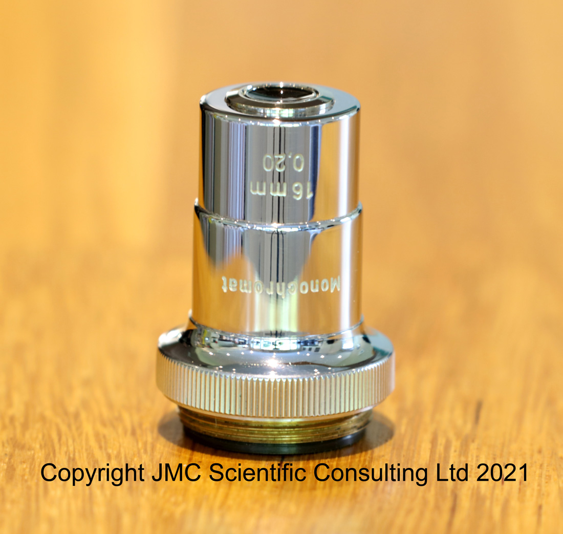
Those that have read my posts before will know that I have a bit of a thing for UV imaging, and that I have been been building a UV microscope capable of imaging down to and below 300 nm. While doing so I’m always on the look out for second hand equipment which can either help with the work, or is of historical value to the whole area of UV microscopy. Today’s post provides some historical context to the development of UV microscopy and shows a couple of the early objectives designed for that job – the Zeiss Monochromats.
The key reason for the development of UV microscopy was the goal of improving resolution – as the wavelength decreases the maximum theoretical resolution that can be reached improves. It made sense therefore to move from visible to UV to see what could be achieved. This increase in resolving power is quite marked, as was noted in ‘Practical Photo-Micrography’ by JE Barnard, 1911, “The objectives made for direct use with ultra-violet light are called ‘monochromats’, and the wave-length for which these are corrected is 275 µµ [275 nm]. The N.A. of the highest power lens in the series is 1.25; but by the virtue of the shortness of the wave-length of the light, the resolving-power is equal to an objective used with white light of 2.5 N.A. – an objective which of course at the present time it has not been possible to produce.”. And nor is it today over a 100 years later. As a side note, the textbook used 275 µµ for the wavelength, and I added the [275 nm] as nm is more commonly used today. As a good friend reminded me, the way the book showed it is a little odd and a more correct way of showing it would be 275 mµ, or as is given on the objectives below 0.275 µ. Not sure why it was shown like this, but wanted to clarify in case of confusion.
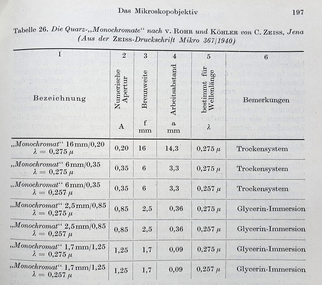
What are these ‘monochromats’? Zeiss produced a range of them with focusing distances from 16 mm down to 1.7 mm, and these were summarized in a table in ‘Die Wissenschaftliche und Angewandte Photographie’ by Kurt Michel, 1957;
Range of ‘monochromat’ objective lenses produced by Zeiss.
The Monochromat objectives were made from quartz lens elements, and were designed to be used dry (trockensystem) or with glycerin immersion. Glycerin rather than oil is used for these UV objectives as it remains transparent even down to 250 nm unlike the oils. They were also designed for use at specific wavelengths in the UV – 0,257 µ [257 nm] and 0,275 µ [275 nm]. These wavelengths were chosen as they are the strong emission lines for mercury (in mercury xenon lamps) and cadmium (from a cadmium arc source) respectively. This does not mean that they can be used at other wavelengths, but it is likely that image quality would suffer as a result. The 16 mm Monochromat might be a later edition to the range, as although it is mentioned in Michel’s book of 1957, it did not appear in Barnard’s text of 1911 (which only mentioned 6 mm, 2.5 mm and 1.7 mm objectives).
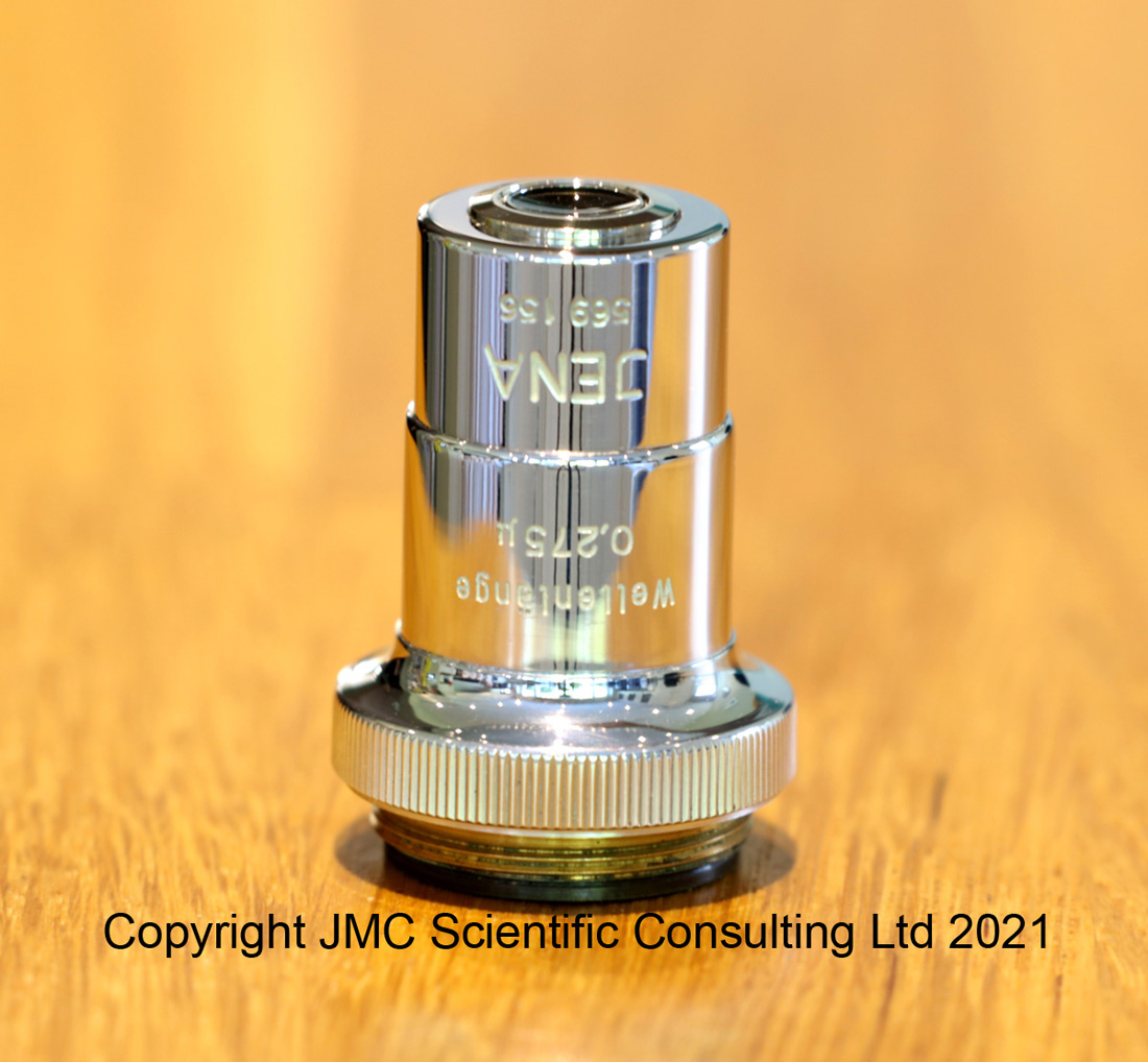
Enough waffle from me, what do these look like? I’ve been fortunate enough to find two of these objectives a 16 mm one and a 1.7 mm one. The 1.7 mm one was for sale on a ‘well known internet auction site’ and has come over to the UK from Ukraine, the 16mm one came from Germany where it became available for ‘the cost of the shipping to the UK’ as it was of no use to the original owner. It’s nice when that happens.
Here’s the 1.7 mm one, with its original objective keeper.
And the 16 mm one;
Both of these were designed to be used with the Cadmium line at 275 nm and both are RMS threaded. In theory they should be for a 160 mm tube length microscope, which is what I have, so I will certainly be trying these out. However it wont be at 275 nm – the lowest I can go with my current setup is 313 nm, and I have no plans on building a cadmium arc lamp (‘elf and safety and all that). I’m expecting relatively soft images, especially when compared with the Ultrafluar lenses, but you never know. Slightly worryingly, JA Needham in ‘The Practical Use of the Microscope’, 1958, said that “The quartz monochromats were corrected for one wavelength (275 mµ) [275 nm] and could not be employed with other wavelengths in the ultra-violet.”. However we shall see after some testing. I’ll also run these through my lens transmission measurement setup to get their transmission between 280 nm and 420 nm. While I’m not expecting any surprises with them (as they should be of all quartz construction), I like to check all new lenses that come in.
The history of imaging and microscopy is fascinating, especially when you dig into the details of how these amazing scientists and engineers tried to push the boundaries of what was achievable at the time. UV microscopy while being a technique that developed over a 100 years ago, is seldom used today as other ways of improving resolution have since come along. However it has huge potential in the field of imaging sunscreens, so is an area I will be continuing to explore and develop. Thanks for reading, and if you want to know more about this or other aspects of my work, I can be reached here.
When I’ve had a good experience with a supplier I like to try and mention them on my page, if nothing else as a bit of thank you. This brings me to Tangsinuo, a Chinese optical filter supplier. I recently found myself in need of some UV transmitting filters in larger sizes than I would normally be able to buy from Schott or other conventional suppliers. Big filters tend to command big (really) price tags even when they are available and this ruled out the more conventional suppliers for this work. ZWB glass is often seen advertised on ebay and other sites as being ‘equivalent’ UG1, UG11 and others, although some of the transmission graphs that come with the adverts have left me wondering how good they actually are.
One supplier – Tangsinuo – has been mentioned a few times on the UV photography forum which I’m member of, so I reached out to them to see if they could do large filters (200mm square) using the glasses I was interested in and was pleasantly surprised to find out that they could, and that they were very cost effective. In the end I placed an order for some 200mm square ZWB1 and ZWB3 glass, some 77mm diameter mounted filters in ZWB1 and 3, some 52mm filters in ZWB3 at different thicknesses, and also a load of fused silica 1mm thick microscope slides (75mm x 25mm) which are normally quite expensive items. All in all the price as extremely good even when I paid for expedited delivery – just over a week from China to the UK using tracked delivery.
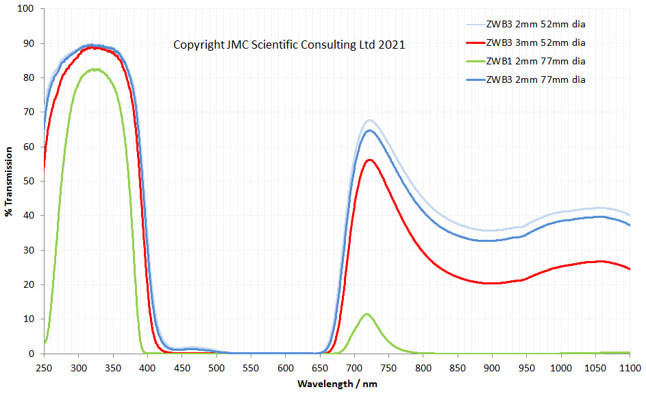
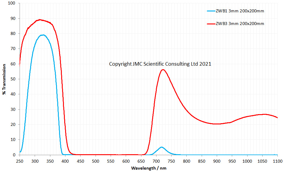
So, how did they look? Transmission spectra of the filters, and the filter thicknesses, are given below (as measured using my Ocean Insight FX and STS spectrometers).
Transmission spectra of 77mm and 52mm camera filtersTransmission spectra of 200mm square filters
ZWB1 is said to be equivalent to Schott UG11, and it looks similar, although does leak a bit more IR than the Schott for an equivalent thickness. ZWB3 is said to be equivalent to Schott UG5, and again it looks similar. Overall, very impressive especially given the price.
I’ve not shared the transmission spectra of the fused silica microscope slides here, as well they are pretty much a flat line from 250nm to 1100nm and no where near as interesting as the filters.
My filters had a good surface finish (no surface striations which can sometimes be seen with some of these Chinese filters – I have a couple myself) and were chamfered at the edges.
So, thank you Tangsinuo. It should also be noted that they are open to working with customers on custom sizes and thicknesses too which is great to hear. Great prices and professional customer service are nice to experience, so please keep it up. If you’d like to know more about this or any other aspect of my work, you can reach me here.
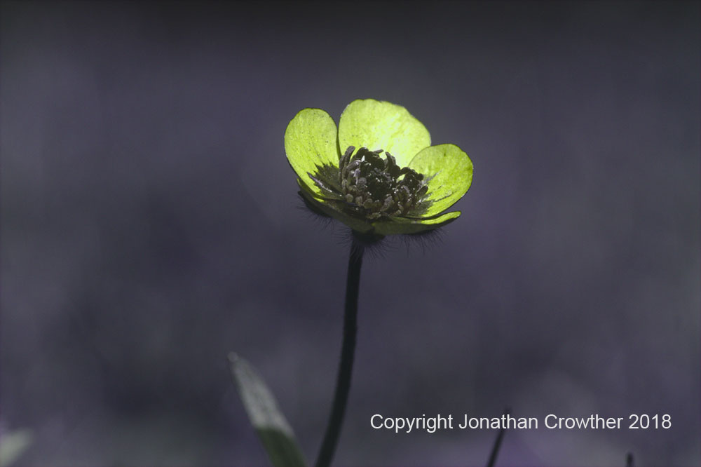
As a photographer who spends a lot of time working outside of the visible spectrum I regularly use filters on my lenses or inside my camera to isolate the wavelengths of light I’m interested in seeing.
Buttercup in UV, taken with UV converted Canon EOS 7D camera and Zeiss 105mm UV Sonnar on extension tubes
However filter choice can be far from straightforward, especially when imaging in the UV region. Today, I’ll give a quick example of why this can be a problem. First though a question – when is a filter not a filter? Take a red filter, which is often used in black and white photography to darker skies and lighten foliage. What is it doing to the light? What a dumb question, it’s letting red light through. Well, yes, it is, but then a simple clear glass filter would let red light through. With filters it’s not so much about what they are letting through (although that is obviously important), it’s about what they don’t let through. A red filter is red because it blocks light that isn’t red – it lets red through while blocking other wavelengths. When imaging in the UV region, this blocking becomes very important, because cameras are relatively insensitive in the UV region compared to the visible and IR regions. If the blocking on the lens isn’t up to scratch hen wavelengths you’re not interested in can make it through to the sensor and contaminate the image.
There are two main types of filters that photographers use – ionic filters such as Schott UG11 or Hoya U-340 which filter the light using the bulk properties of the glass itself, and dichroic filters which have a thin coating on one or both surfaces the glass which provides the filtering. Dichroic filters can just be on plain, colourless glass or they can be applied to an ionic filter, so the filtration is provided by the coating in addition to the bulk of the glass. An example of a dichroic filter in widespread use for UV photography is the Baader Venus U (commonly known as the Baader U).
Dichroic filters can be tailored to allow for very sharp cutoffs on the filters, and also high transmission, while ionic filters tend to have much smoother transitions. On the face of it, dichroic filter would seem to be perfect, for the UV photographer, offering high transmission and in theory excellent blocking of out of band wavelengths.
But there is a bit of an issue with dichroic filters which can be a problem if not considered. That is the effect that the angle between the incoming light and the filter has on its transmission properties.
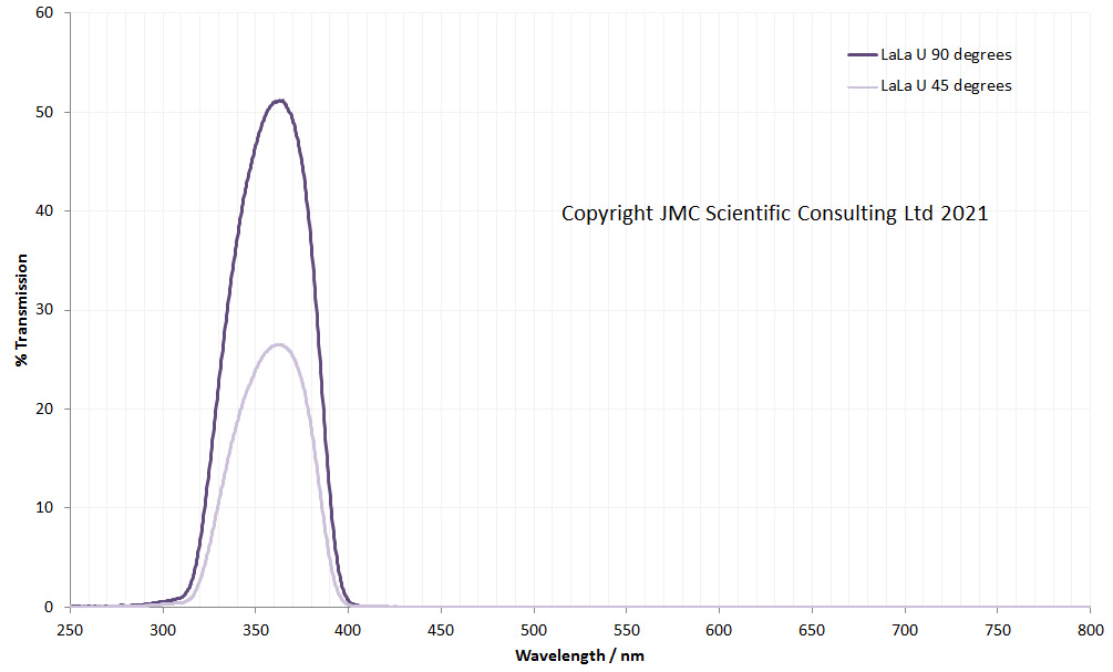
Let me explain. I shall start with an example of an ionic glass UV filter – the LaLa U made by UVIRoptics. The LaLa U is an ionic filter stack which lets UV through while blocking visible and IR. Here’s what the transmission through the filter looks like at two angles – light incoming at 90 degrees to the filter, and at approximately 45 degrees.
LaLa U filter stack transmission with the light at 90 degrees and 45 degrees to the surface of the filter
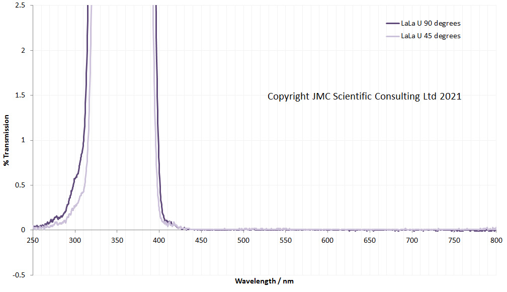
Transmission was measured using an Ocean Insight FX spectrometer and light source. Tilting the filter to 45 degrees drops the transmission (as the light is going through a lot more glass), but the shape of the transmission peak doesn’t change. If the graph is replotted to look for leaks, I get the following.
LaLa U graphs replotted to look for leaks
As expected, the LaLa U has good blocking in the visible and IR regions, and tilting it does not make a difference.
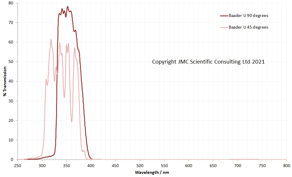
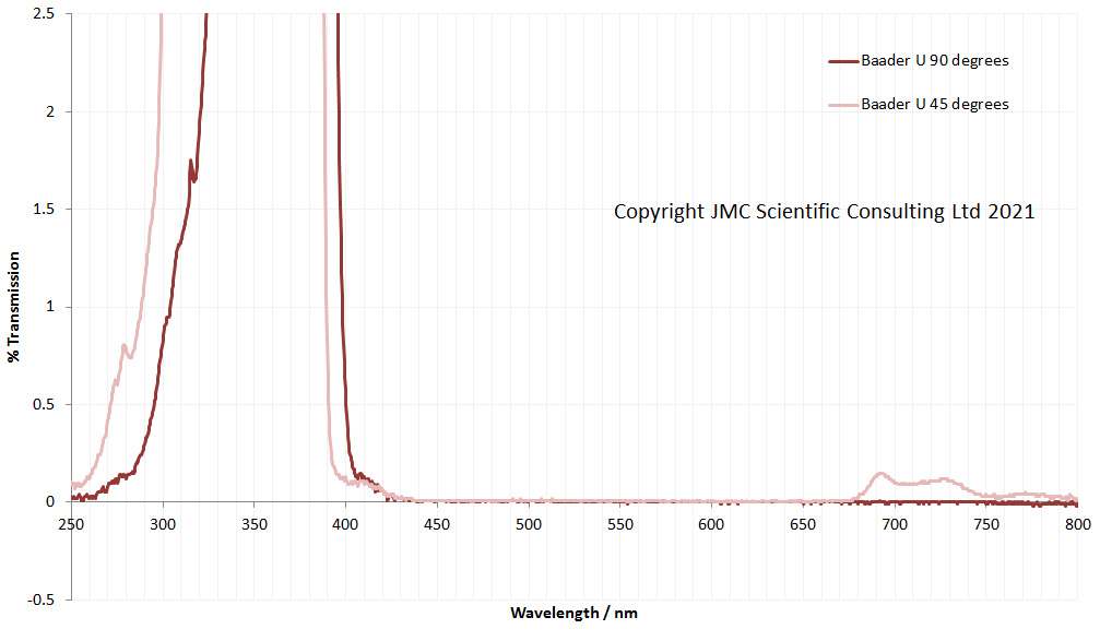
Now, what happens when we look at the dichroic Baader U filter in the same way? First graph, full scale, second graph magnification to look for leaks.
Baader U transmission with the light at 90 degrees and 45 degrees to the surface of the filterBaader U transmission graphs replotted to look for leaks
The Baader U behaves very differently as it is tilted. Unlike the ionic LaLa U filter, the Baader U transmission spectra shifts to a shorter wavelength when the light is at 45 degrees to the surface of the filter. In addition the UV transmission profile is much more jagged in shape. Also, and even more concerning it is now letting in light above 680nm, and while 0.2% transmission may not seem like a lot, this can be an issue for UV imaging.
Some dichroic filters have even tighter transmission regions than the Baader U. Examples of these include Edmund Optics and Thorlabs 10nm bandpass filters. These both claim to have high blocking of out of band wavelengths, while at the same time giving high throughput in the region of interest. I use these for filtering light sources and also for imaging in front of camera lenses, although they are normally used more for filtering light sources than imaging.
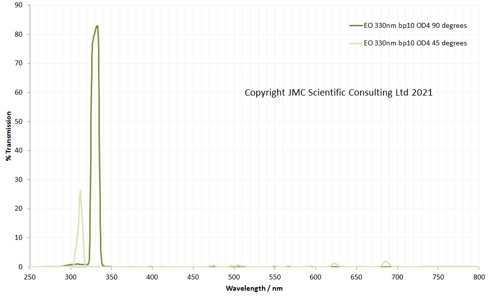
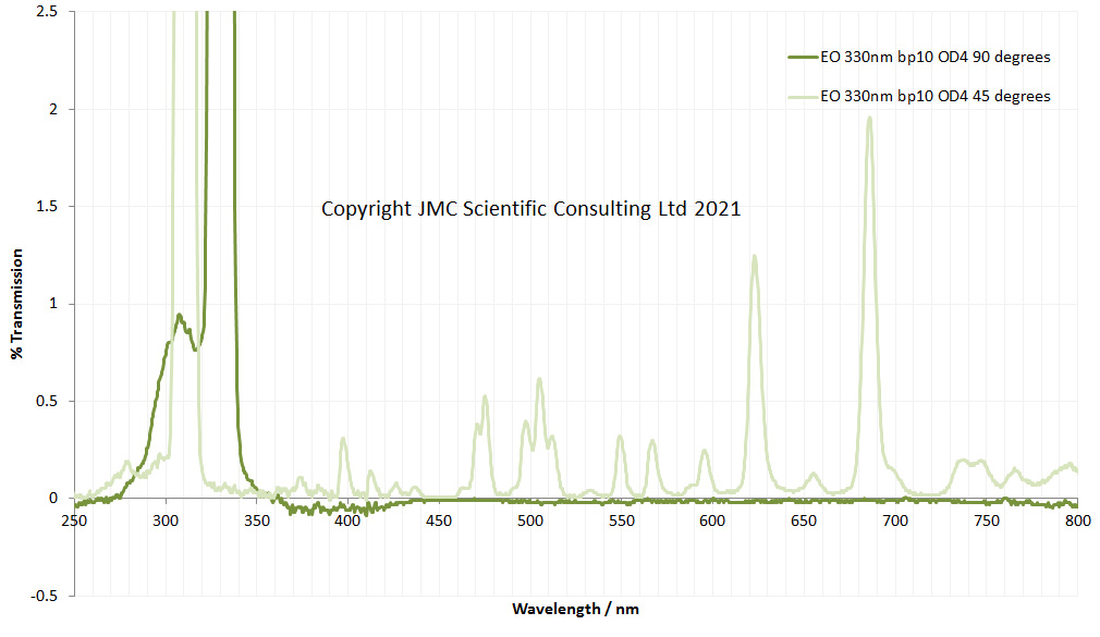
How do these behave? Firstly, the Edmund Optics 330nm, 10nm bandpass filter which claims OD4 blocking (<0.01% in the out of band regions) and has a mirror finish on both surfaces of the filter as a result of coatings.
Edmund Optics 330nm 10nm bandpass filter transmission with the light at 90 degrees and 45 degrees to the surface of the filterEdmund Optics 330nm 10nm bandpass filter transmission graphs replotted to look for leaks
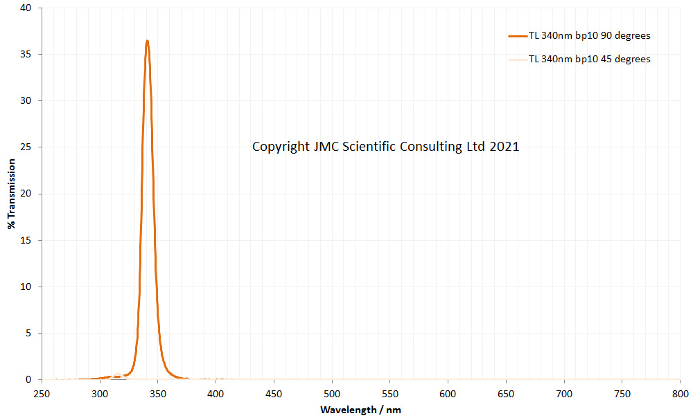
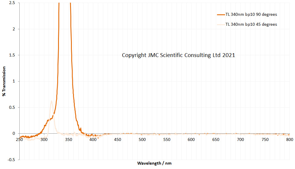
And next, the Thorlabs 340nm 10nm bandpass filter.
Thorlabs 340nm 10nm bandpass filter transmission with the light at 90 degrees and 45 degrees to the surface of the filterThorlabs 340nm 10nm bandpass filter transmission graphs replotted to look for leaks
First, I should mention that the Edmund and Thorlabs graphs highlight some of the issues when using a solid state spectrometer like the one I have for looking at filters with really sharp peaks, and that is the artefacts that can occur at either side of the main peak in the profiles. The slight dip in transmission below 420nm and above 700nm for them both is not the spectrometers fault. That was all mine. I didn’t recalibrate the baseline while running these 4 filters, so the last two (Edmund Optics and Thorlabs) are showing a slight drop below 0% transmission below about 420nm and above 700nm. It was a sunday morning, I hadn’t had my coffee yet. Excuses over, and despite those effects, how does tilting impact the spectra? With the Edmund Optics filter, peak transmission drops from 330nm to 310nm, and reduces in intensity. Very worryingly though, it starts to let significant amounts of light through across the visible spectra and into the IR. This would be expected to seriously contaminate a UV image if not dealt with properly.
The Thorlabs filter peak transmission drops from 340nm to about 315nm, along with a huge drop in intensity. However unlike the Edmund Optics filter, it doesn’t develop obvious leaks in the visible or IR region (at least up to 800nm).
I should emphasize at this stage that these Edmund Optics and Thorlabs filters have not been developed for use as camera filters, and are designed to work with the light hitting them at 90 degrees to their surface, so it is not unexpected to see their performance being degraded when the light hits them at 45 degrees. Also, I’m not clear on whether other filters in their ranges behave in exactly the same way. Dichroic filters are tailored for the wavelength they are to be used at, as such they could well vary in the transmission they show at different angles.
If you’ve made it this far and are suffering from graphical overload, you can now take a breather – no more graphs. Why are these changes important and more importantly, what can be done about them if using these filters for photography?
As for the ‘why’ consider how light goes through a lens and reaches a camera sensor. It doesn’t just come from directly in front of the camera, but as a cone of light. The wider the focal length of the lens, the wider this cone. 45 degree either side of normal to the lens is pretty wide, equating to a focal length of about 22mm on a camera with a sensor the size of a 35mm SLR. As a result of this the spectral distribution of the light reaching the edges of the image could be very different to the light in the middle of the image, leading to strange colour shifts across the final UV image.
The 45 degrees used for the test here is a pretty tough harsh based on this, and the effects would be expected to become less severe as the angle gets closer to 90 degrees to the surface of the filter. For example a 105mm focal length lens has angle of about 23 degrees on a full frame (35mm) sensor camera. On longer focal length lenses, like a 105mm one, the effects described here would be expected to be much less pronounced.
What can be done about this? Longer focal length lenses will be less of an issue, so be aware that dichroic filters can have an issue when using wide angle lenses. Use a good and appropriately sized filter hood to block as much light coming in from the side as possible. If the mechanics allows for it, try mounting the filter behind the lens (between the lens and body of the camera). Although be aware that mounting a mirror finish filter just in front of the sensor can present its own problems with reflections. Perhaps the most obvious thing to do is consider using an ionic glass filter stack instead of a dichroic one. If the slightly reduced transmission is something you can live with, and there is no need for ultra sharp cutoffs to the light, then this can be the most flexible approach and can be used on a wide range of focal length lenses without changing the spectral distribution of the wavelengths getting through to the sensor.
This aim of todays discussion is not to have a downer on dichroic filters – they are extremely useful, offering high transmission and well defined cutoffs – the aim is to point out that depending on how they are being used they can have issues which need to be dealt with to get the best out of them.
There’s been a lot of graphs today, so well done if you’ve made it this far. Thanks for reading, and if you want to know any more about this or any other aspect of my work, you can reach me here.
The Collodion imaging process harkens back to to early days of photography. A photosensitive layer comprising a nitrocellulose carrier and silver halide on a glass plate forms the image capture media, and the result is a negative image of the subject – essentially a precursor to the more recent use of film photography.
Unlike modern films and digital cameras, Collodion plates are not sensitive to the full visible spectrum, being essentially unable to capture the longer wavelengths, while at the same time being sensitive to some UV. As such the images captured with them look very different to modern images, with very washed out skies being a common feature, along with darkened foliage. Skin tends to be captured as darker than it appears in normal visible light images (due to the increased absorption of short wavelength light be melanin) along with an emphasis of surface texture (again due to the short wavelengths being imaged).
Something I’ve wondered about since starting with digital photography is how to go about replicating the effects of Collodion in a digital camera. The first step was to try and understand the spectral response for Collodion plates. Some work has been done on this by LundPhotographics, who showed that it was mainly sensitive between 320nm and 520nm. This correlates well with the spectral response of an un-sensitized photographic plate as shown in “The Theory of the Photographic Process” 4th Ed by TH James (Figure 17.42 on page 512) which showed sensitivity between about 360nm and 510nm. With the work discussed by TH James they acknowledge that drop in sensitivity towards the blue end was a factor of the use of tungsten light which has limited blue and UV. Therefore the LundPhotographics range of 320nm to 520nm is a good start point, especially when imaging with sunlight.
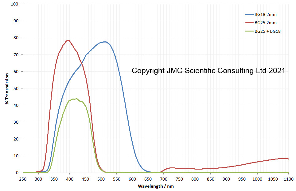
The next stage was filter choice. I had a feeling Schott BG25 would be a good filter material to use for this as it has good transmission in the UV and blue regions. However it has a problem in that it transmits IR as well, and as digital cameras are very sensitive to IR this would need to be blocked. There are a range of filters which can be used for this such as Schott s8612 and BG39. During an eBay trip one day I came across a seller who had some 2mm thick BG25 along with 2mm thick BG18 (which is also a good IR blocker). Even better these were large – 75mm diameter – and cheap. So a quick purchase later, and some 77mm filter rings from Kood International, and I had some filters which could be used on lenses with a 77mm filter thread making them very versatile.
This first thing to do was measure the transmission spectra of the filters, and I did this using my Ocean Insight FX (UV and visible) and STS-NIR spectrometers which I use for a lot of my work. This gave me transmission spectra for the filters between 250nm and 1100nm as shown below.
BG25 and BG18 transmission spectra, individually and combined
By combining the two filters, the result was transmission between about 330nm and 510nm, with good blocking at shorter and longer wavelengths (especially the IR) – the green line in the graph above. This correlates well with the range for Collodion sensitivity derived by LundPhotographics. One slightly odd thing with the spectra – the BG25 was letting through less IR than I would have expected for a 2mm thick one based on the Schott online filter calculator. Measurement of the thickness showed it to be 2.1-2.15mm thick, but even that could not account for the transmission in the IR. Perhaps it’s just an odd batch (the filters were old ones) or perhaps the specs have changed slightly over the years. I’ll never know for sure on that. However the BG18 would do a good job of blocking even if the IR transmission of the BG25 was little more than it is.
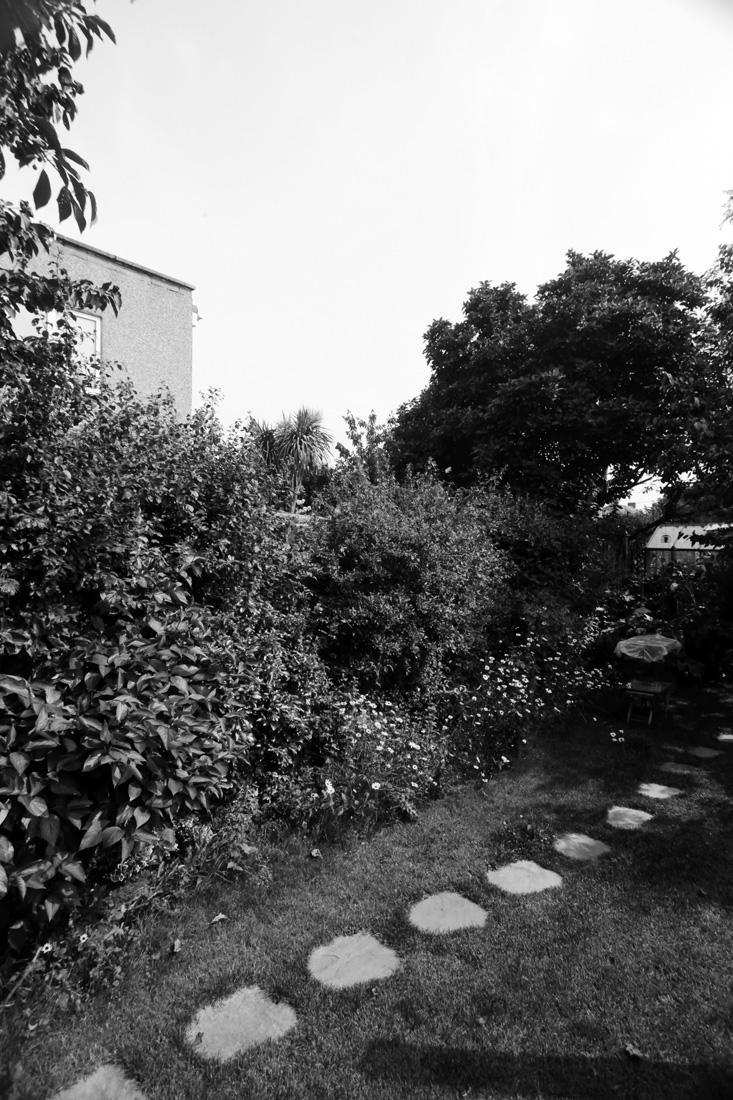
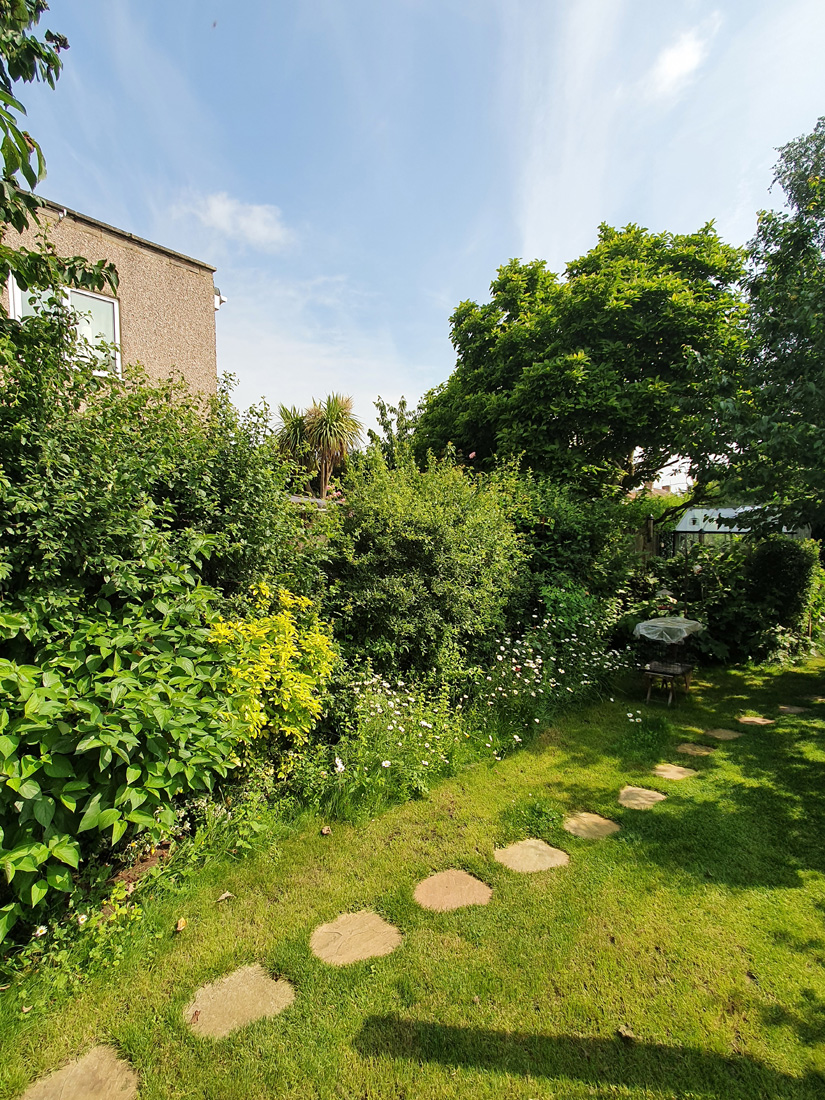
To capture an image, I need a camera which was sensitive to the 300-550nm region, and for this I used my Canon EOS 5DSR multipectral conversion. The lens was a Canon 17-40 f4 (at 19mm). Image captured in my garden in direct sunlight, and as a comparison shot, a visible light image taken with a camera phone at the same time.
Firstly the digital Collodion image.
Digital Collodion image
And the normal visible light image.
Visible light camera phone image
As expected the digital Collodion image has washed out sky and darker green foliage when compared to the visible light image. In hindsight I could have used a monochrome converted camera as this would have boosted the UV sensitivity compared to the camera used here, although this would have needed me to use a different lens as well, as this one wouldn’t have let that much UV through. So my Collodion image here isn’t as ‘UV heavy’ as it could be and is mainly comprised of long wavelength UV from about 380nm and blue light. Lens and camera choice is certainly something to consider for future work with the filters.
Revisiting old photographic processes forces us to think about the image capture process as a whole and the factors that are important to it. In doing so we learn more about the methods we are using, their limitations and how they can be improved. This type of thought process is vital to the world of supporting claims for products, as without knowing how the methods we use work, how can we understand their limitations – what they can and can’t be used for?
If you made it this far, thanks for reading and if you’d like to know more about this or any other aspect of my work, you can reach me here.


