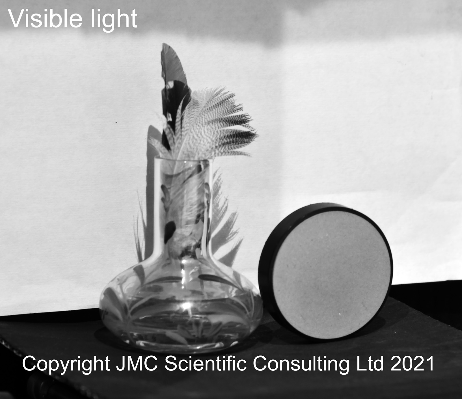
Back in April 2020 when Lockdown 1.0 kicked in in the UK, I decided it was time to try and learn a new skill. So it was that I embarked on a journey into the complex and fascinating world of microscopy. What I knew about microscopy at that point could have been written on the back of a very small envelope. Jumping in with both feet and having done practically no research at all into the area, I bought an Olympus BHB from the 1980s, which was, well, in need of a bit of love and attention. Affectionately named ‘Project Beater’ due the condition it arrived in, I started documenting my journey into microscopy here, and have been providing regular updates ever since.
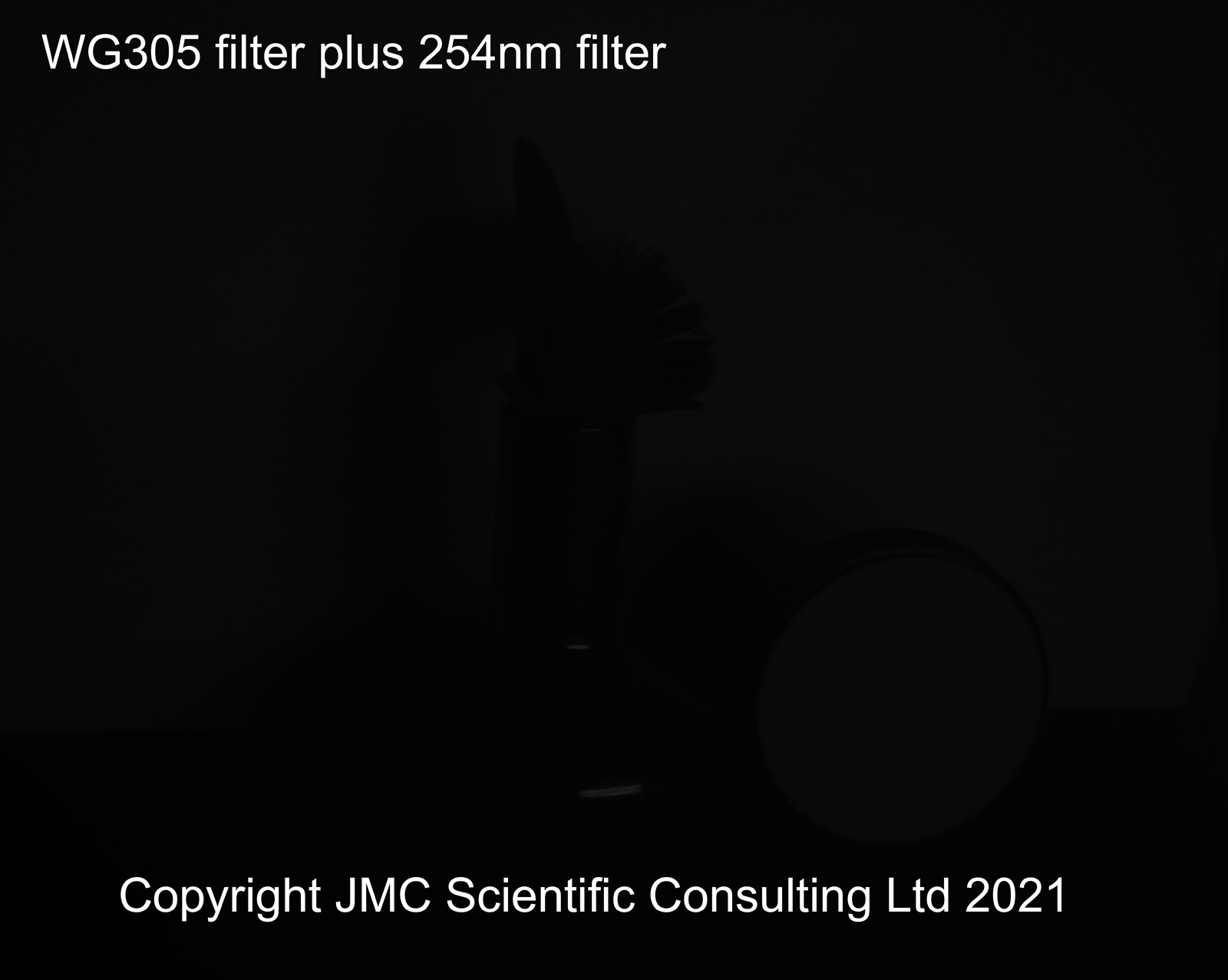
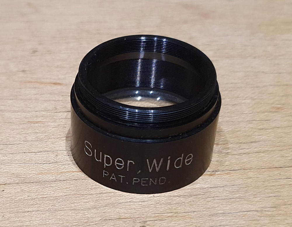
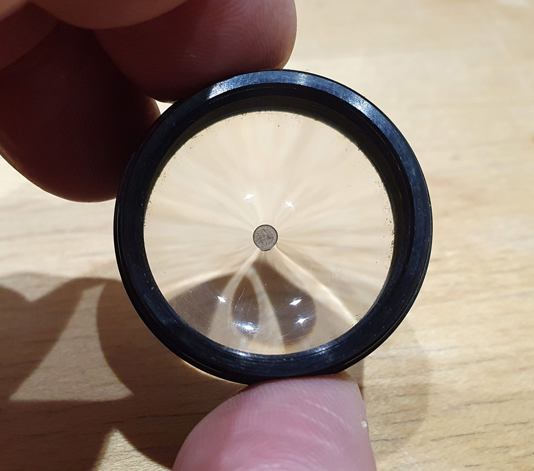
Not long after getting the microscope, I started wondering whether it would be possible to make my own UV imaging system, capable of doing transmission microscopy down to and even below 300nm to help with my sunscreen research. Commercial UV transmission microscopes do exist but they are incredibly expensive to buy. To build one would be a monumental challenge, as glass absorbs short wavelength UV, and microscopes have a lot of glass in them. And when I say ‘a lot of glass’ I really was in for a shock as to how complex making a UV microscope would actually turn out to be. Since then I have been constantly modifying, tinkering, buying (oh, there has been plenty of buying) and tweaking this little Olympus BHB with the eventual aim of removing all the glass from the optical system that leads to the camera, replacing it with UV fused silica and other UV friendly materials.
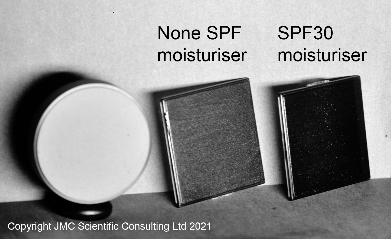
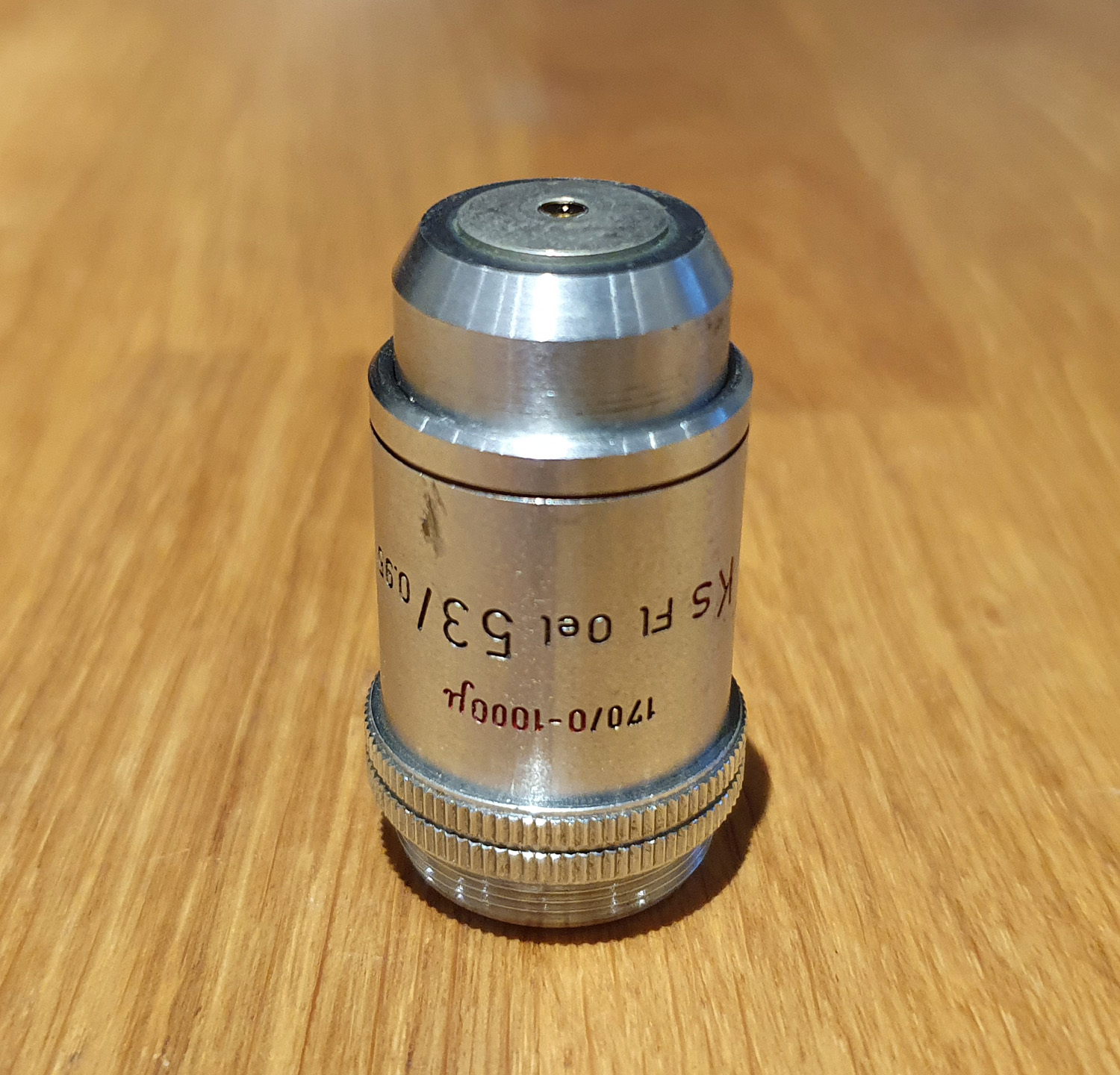
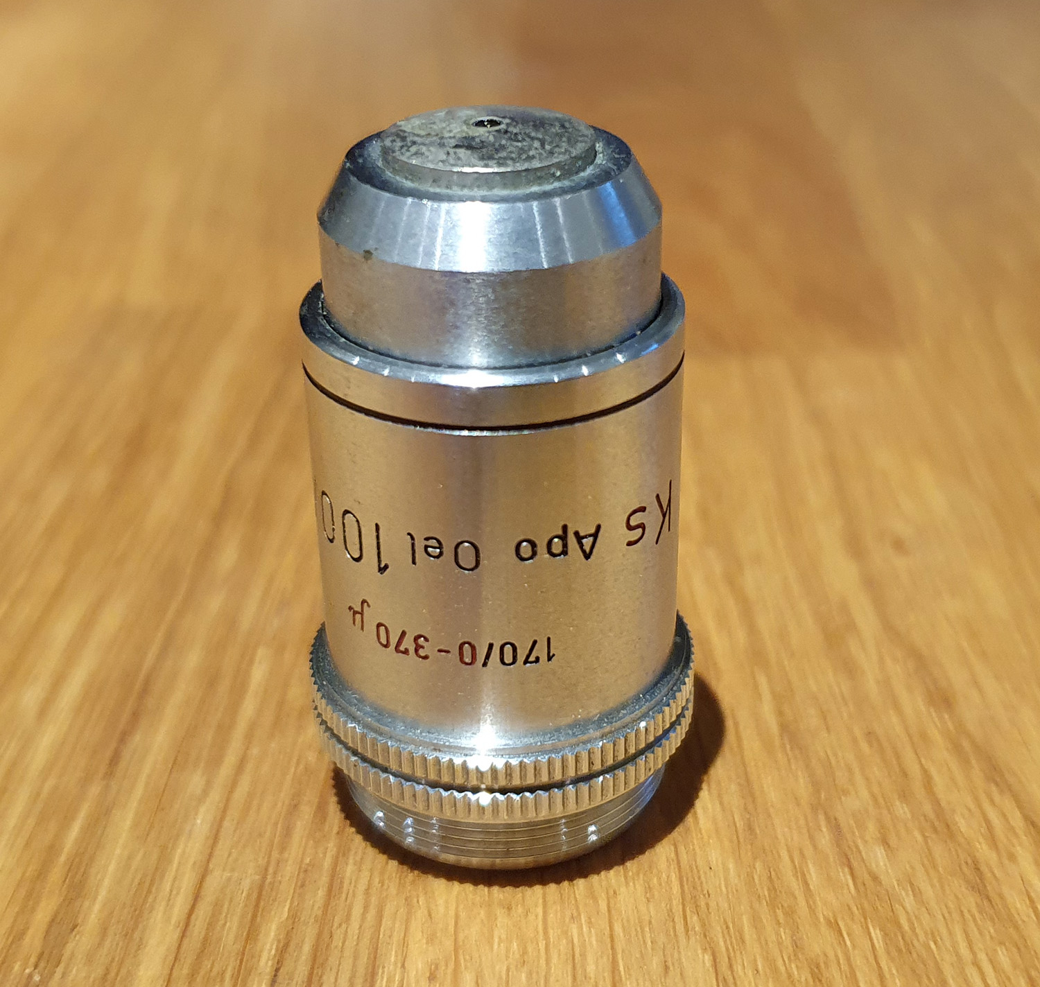
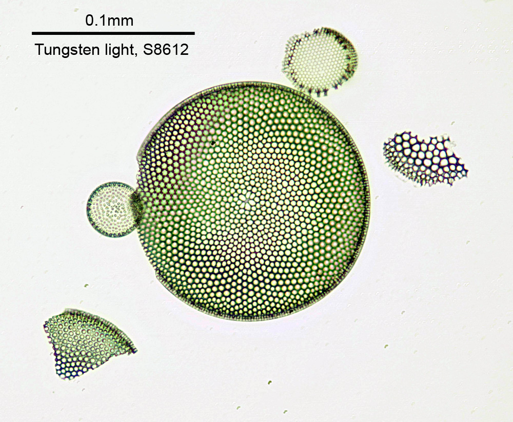
This brings us to February 2021, 10 months after the initial purchase of Project Beater. With the final pieces of the UV conversion carried out, it was time to test it out and see whether it would even be able to image in the UVB region down at 313nm. 313nm was chosen as a test wavelength, as the mercury xenon lamp had a good strong line there, and the camera should still have some sensitivity there (it drops very quickly below that). For a test subject it made sense to use a sunscreen formulation which had a UVB absorber in the oil phase, and no UV absorbing ingredients. This way it should look darker at 313nm than at 365nm or in the visible. After applying a dot of product onto a quartz slide and adding a quartz coverslip, imaging in the visible region with a 32x Zeiss Ultrafluar objective gave the following.
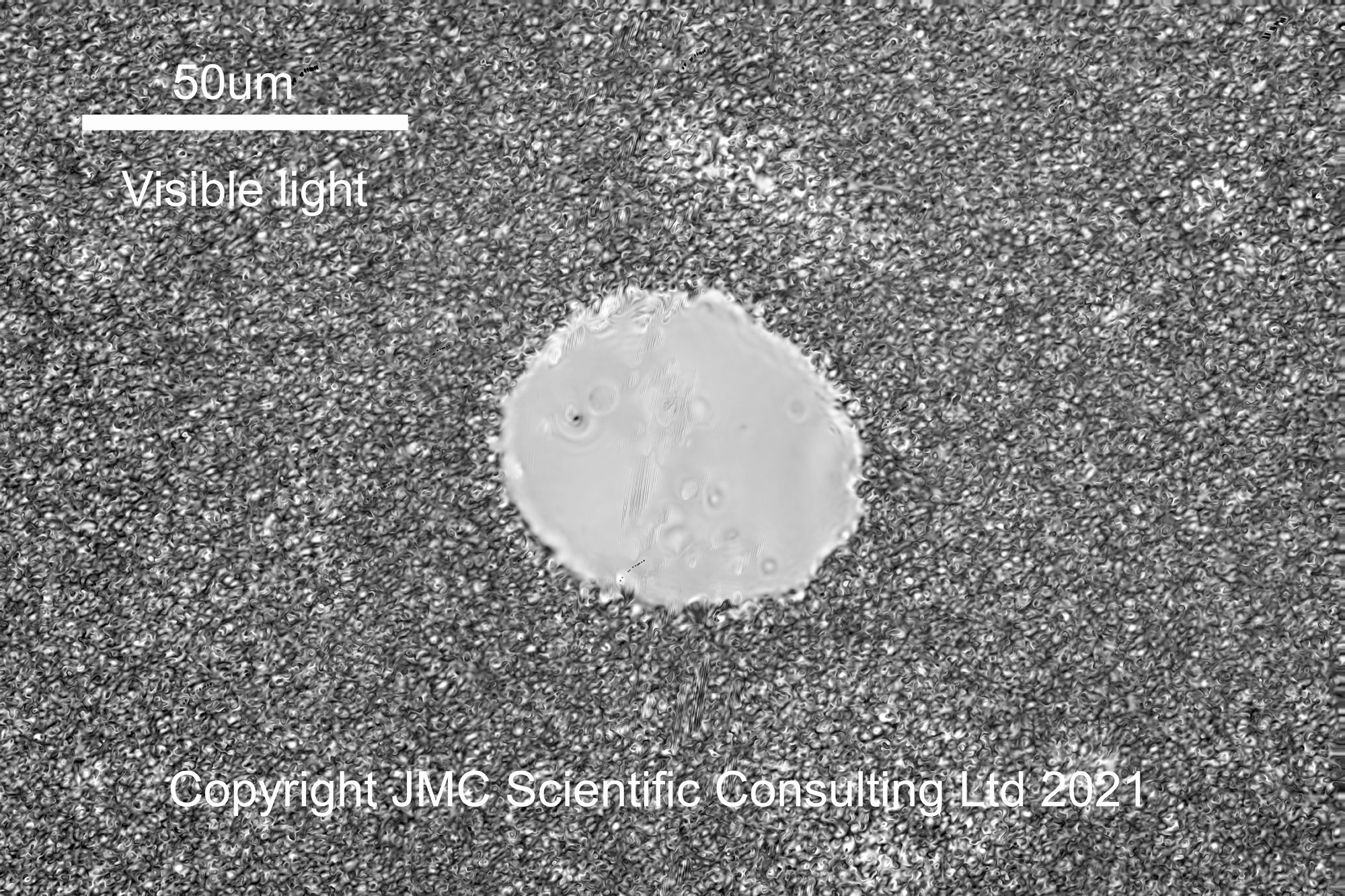
The circular feature in the middle of the image is an air bubble in the formulation, and surrounding it is a dense network of small oil droplets in a water based continuous phase. The next wavelength to image was 365nm (UVA).
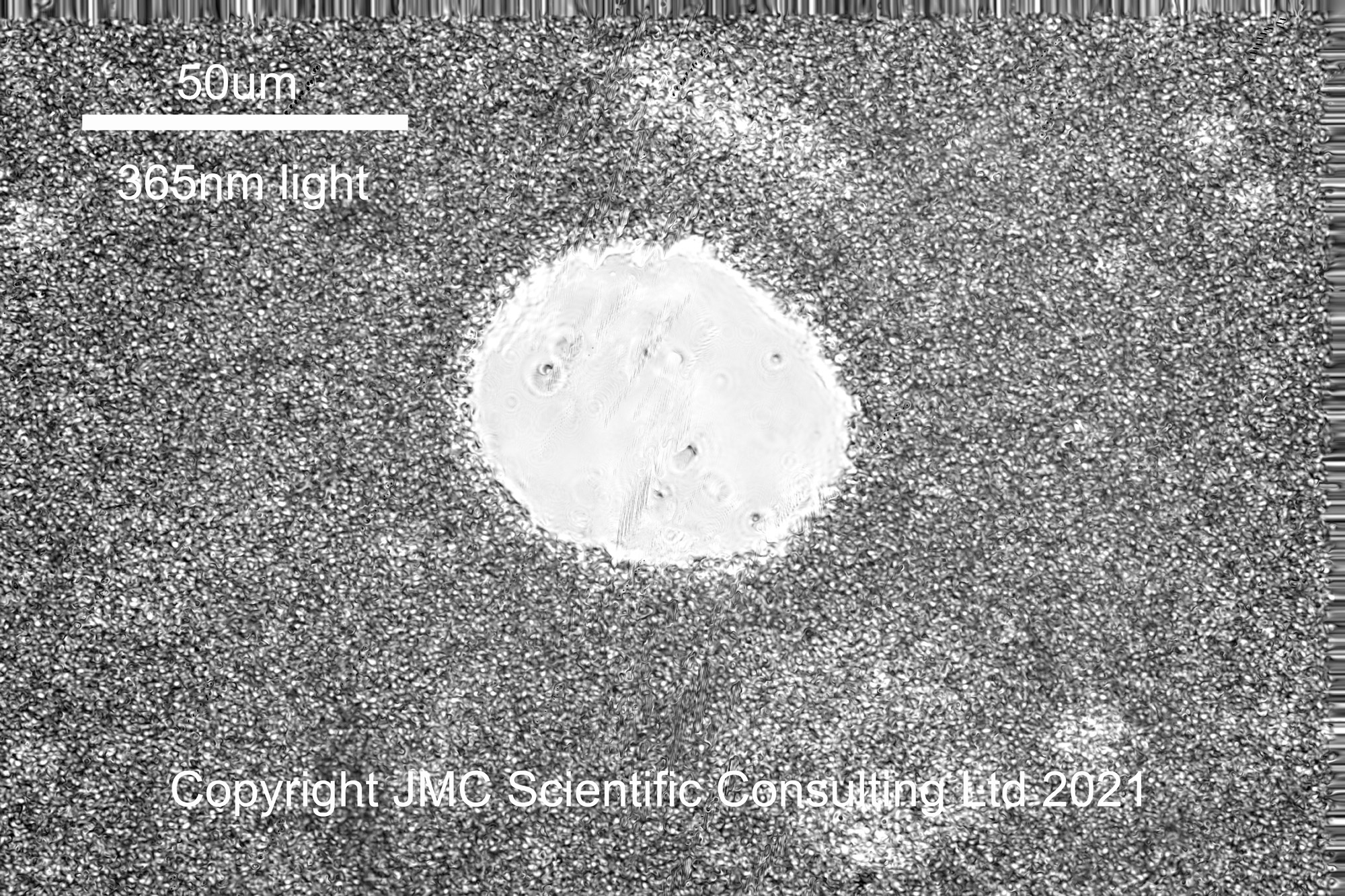
365nm was chosen for imaging in the UVA, as the mercury xenon lamp has a strong line there. To filter out unwanted wavelengths from reaching the camera, I used a 365nm bandpass filter from Edmund Optics. This blocks wavelengths outside the region of interest with an efficiency of OD4 (optical density 4, or in other words transmission in the out of band regions is <0.01% on average). The 365nm image looks similar to the visible one, which it should do, given the sunscreen ingredient it contains does not absorb UVA. Something to notice, in addition to the air bubble in the middle of the image, in the visible and UVA images there looks to be regions where the emulsion looks ‘lighter’, specifically to the top right and bottom right of the air bubble. I shall come back to those regions in a minute.
Once the UVA image was captured, I changed the filter for a 313nm UVB one and imaged the area again, getting the following.
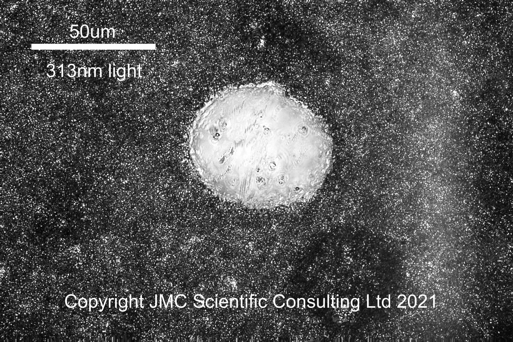
At 313nm the image looks a little different. The air bubble is still visible, but the image looks darker, and those areas which were lighter in the visible and 365nm images now look darker than their surroundings. I suspect these darker areas are oil rich, and the UVB absorbing sunscreen is in the oil phase of the product.
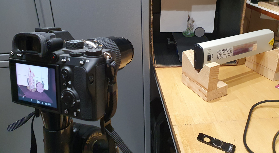
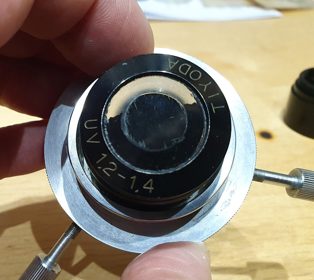
It was great to see a UVB image appear at 313nm. However it certainly has its challenges. With the 313nm filter I have, even though it was rated OD4 for out of band regions, the degree of blocking it offered was not sufficient, and when first tried I was getting some none UVB light coming through to the camera. I had to use another 310nm OD4 bandpass filter in series with the first one, to block unwanted wavelengths (unfortunately I didn’t have a second 313nm filter, but the 310nm still let the 313nm line through). Camera sensitivity was very low at 313nm, and I had to increase the ISO setting on the camera from ISO 400 for the visible region to ISO 6400 for 313nm, and the time to capture an image increased from 1/80s to 30s!!! When you think that each image above is a stack of about 10 images, with slightly different focal points, you start to realise the logistics involved with trying to capture UV images. Oh and I really need to get better at preparing slides – this sample was not the best. One of the scariest things with making these is the knowledge that a quartz coverslip cost about 20GBP, so there is no ‘use it and throw it away’ as with glass ones. Once finished with the coverslip has to be cleaned along with the quartz slide. At 0.35mm thick to 20GBP each, cleaning a quartz coverslip is not a fun job…..
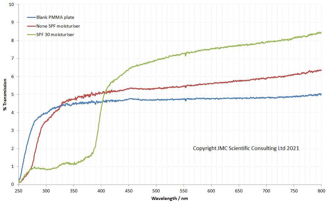
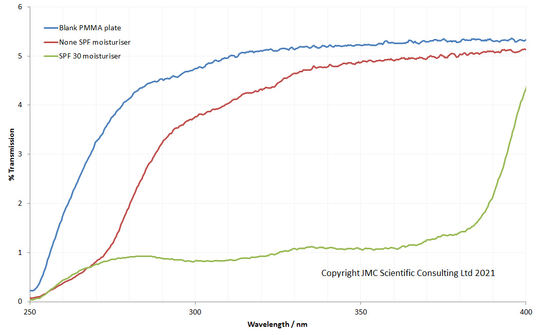
How to try and visualise how the effect of of converting the microscope to UV has had on the throughput of light to the camera? Back in June 2020 when I did my first UVA imaging of sunscreens, I also did some measurements of throughput of light through the unconverted microscope, shown here. Taking that data and normalising the irradiance to the max peak height gives the following.
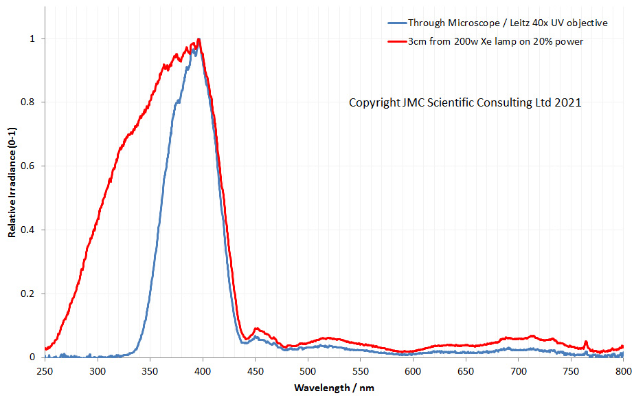
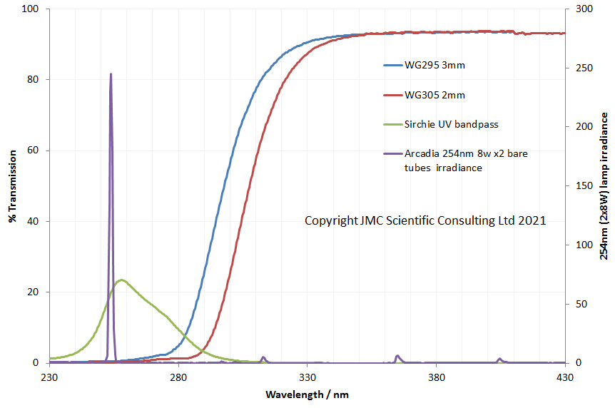
In the graph above the red line shows the output from the 200W Hamamatsu Xenon lamp. It shows a long tail down into the UVB and UVC region, and there is still light present even at 250nm. The blue line is the light having passed through the microscope. This shows that below 400nm, the UV starts to be absorbed straight away. By 350nm, about 75% of the light has been absorbed by the glass in the optics of the microscope, and by 330nm, there is nothing getting through. I was actually surprised by how much UVA did go through the standard microscope, and in that form it would be suitable for UVA imaging, if used with good objectives and ideally a quartz photoeyepiece.
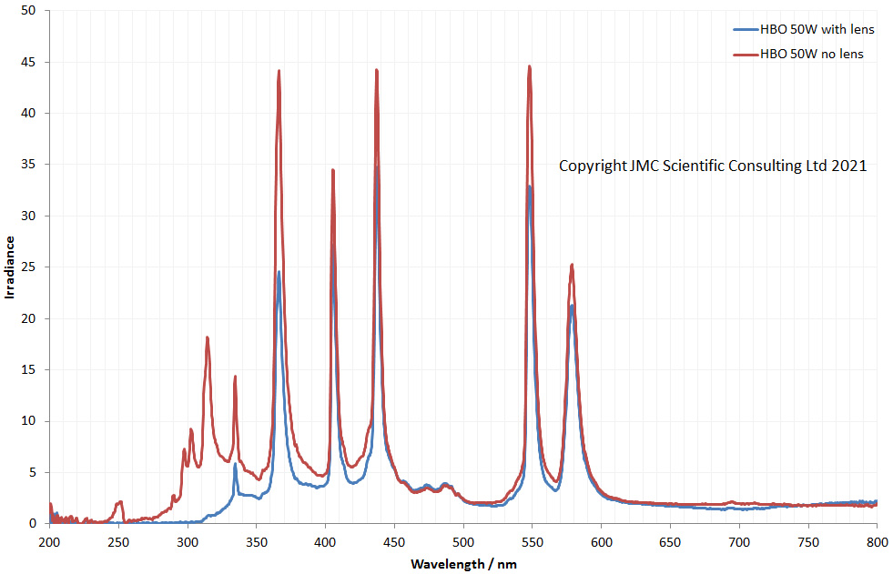
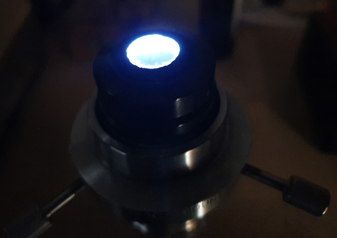
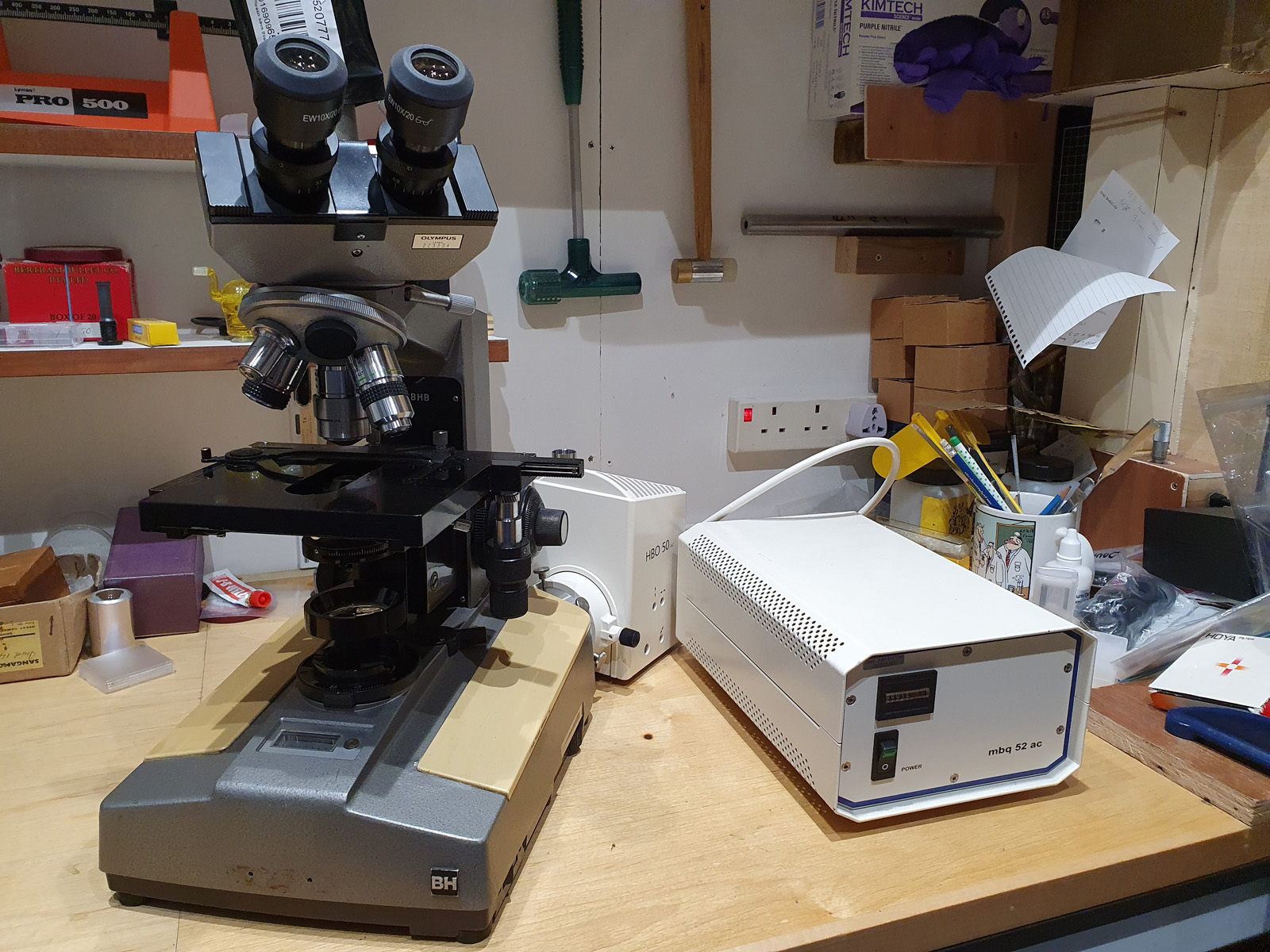
For the final build, I decided against using the Hamamatsu 200W light source, as logistically it was hard to use. I settled on a Zeiss 50W mercury xenon lamp, which while have a more ‘peaky’ spectrum, has strong lines at very specific wavelengths in the UV region. So how does the transmission through the microscope look now it has been converted to UV?

In this graph we now have 3 lines. The blue line is the 50W lamp alone before it is connected to the microscope. The irradiance spectra has peaks because it is a mercury xenon lamp. The red line shows the normalised spectra after it has passed all the way through the microscope to the photoeyepiece at the top, which is where the camera connects. After the conversion to UV, the light going through the microscope has a very similar profile to the original light source, showing only a small reduction down at 300nm, and even down at 250nm. This is because all the glass has been replaced with UV fused silica, and the objectives and and condenser are quartz, UV fused silica, and calcium fluoride. In this graph there is a third line in green. This is the light that comes out of the eyepieces. I added yellow filters here to block light below about 500nm as a safety precaution (the line is much more noisy than the other two due to the complexity of measuring the output from them). I will however still be using UV safety glasses whenever using this, and also using a UV blocking filter over the input whenever I use the eyepieces for focusing.
The goal when I set out on this conversion was to build a microscope which I could use for visible light imaging, as well as down to and below 300nm. Also, it had to be fairly compact as my work surface is not that big. By converting an existing microscope, and using a Zeiss 50W HBO light source, I managed to keep the size down, and retain functionality for use in the visible light region.
It has been a hugely complicated build, but very rewarding and I’ve learnt so much about microscopy and imaging in general. There are of course areas for improvement. The camera I have has low sensitivity in the UVB and by about 300nm would be unusable. At 300nm and below I’d need a UV enhanced camera, but that would require connection to a computer to run it. The Edmund OD4 filters really need to have 2 of them stacked together at 313nm and below, as individually they cannot block the out of band regions of light. This is costly though. Also, to change filters at the moment I need to remove the camera, so doing multispectral images of the same sample is pretty much impossible. Ideally the best thing to have would be a modified tube from the microscope to the camera, which had a opening to put filters in and out. This would however need to be custom made and will have to wait for now. The main thing I can do though is learn how to prepare slides better, especially for looking at emulsions.
If you’ve made it this far, thanks for reading, and if you’re interested in knowing more about this or other aspects of my research, I can be reached here.