
It’s always the same when I attempt some DIY – I start out with a plan, and a pile of bits, and I invariably end up with parts left over at the end, and a nagging question about where they should have gone. It’s been a little like that with Project Beater, my microscope build. As I’ve gone along buying spare parts for it and bits of donor equipment, I’ve ended up with some stuff which I wasn’t really sure what to do with. A couple of weeks ago it dawned on me that I almost had enough parts to make a reflection microscope, to go along with the transmission setup I already had. So back on eBay (for a few more missing parts) and that is precisely what I did….
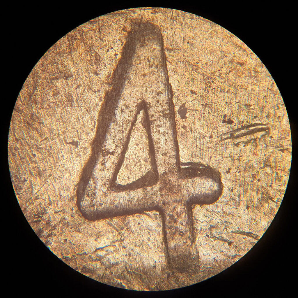
Reflection microscopy relies on top illumination and is used for non-transparent samples. It’s often used for looking at gems, metals, feathers, fabrics, etc etc. Before I show you a picture of the setup though, here’s one of the sample pictures I took to try it out once it was assembled. I’ll leave you to figure it out what it is for now, and come back to it later…..
My setup was based around an Olympus BHM chassis, a reflected light setup placed on top of the microscope, and then a normal or trinocular head on top of that (depending on whether or not I want to take photos). The objectives are old Olympus Neo ones, designed specifically for this type of ‘top down’ imaging as they have a channel around the lens to allow the light to be shone down there rather than through the objective itself. Here’s what it looks like from above.
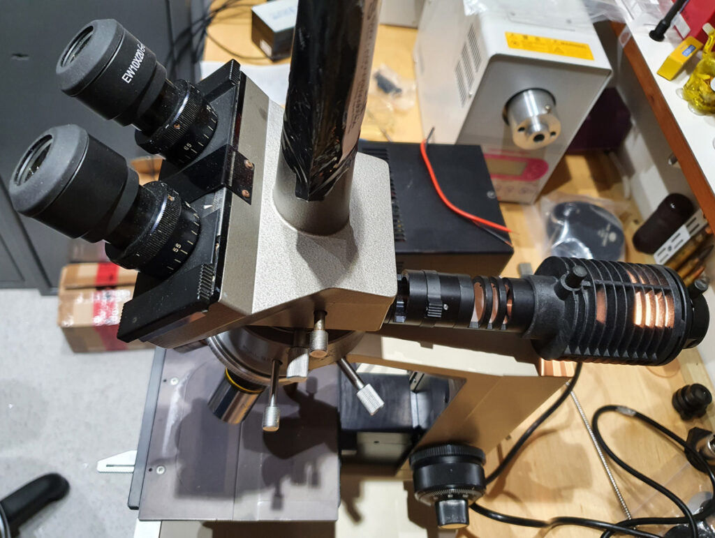
The original light source is a 15W 6V Tungsten filament bulb, but these are both expensive and difficult to source now, and give a very warm colour cast to the image, so instead I just used a 10W cool white LED source I built previously. This gives out plenty of light, and with very little colour cast. Plus it has the added benefit of being virtually immortal.
So, back to the test object. Did you figure out what it is? Here it is in its entirety.
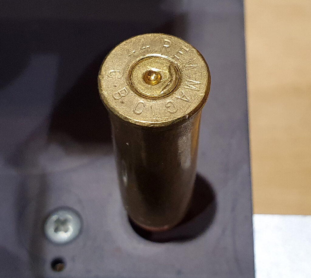
The image was one of the ‘4’s from an inert 44 Remington Magnum round, taken with a 10x Neo objective, imaged using a camera phone through the eyepiece (overall magnification 100x).
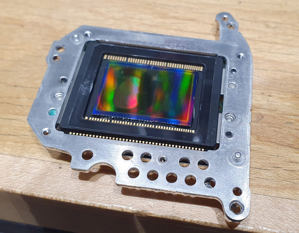
While looking at old brass is one use for these types of microscopes, I did have a different use in mind when I built it. I have some monochrome converted cameras for my UV work, and for a while I’ve been wanting some nice pictures of a camera sensor to show what it looks like as a result of the conversion. So I got a damaged sensor which had been partially converted to monochrome, and as a result had regions which were left untouched, regions which had the microlenses removed, and other parts which had had the microlenses and Bayer filter removed. Here it is (with the area where the Bayer filter has been removed to the left of centre);
What does a camera sensor look like in its normal form? Here we have a reflection image of the sensor from part of it which hadn’t had anything removed, taken with a 40x Neo objective.
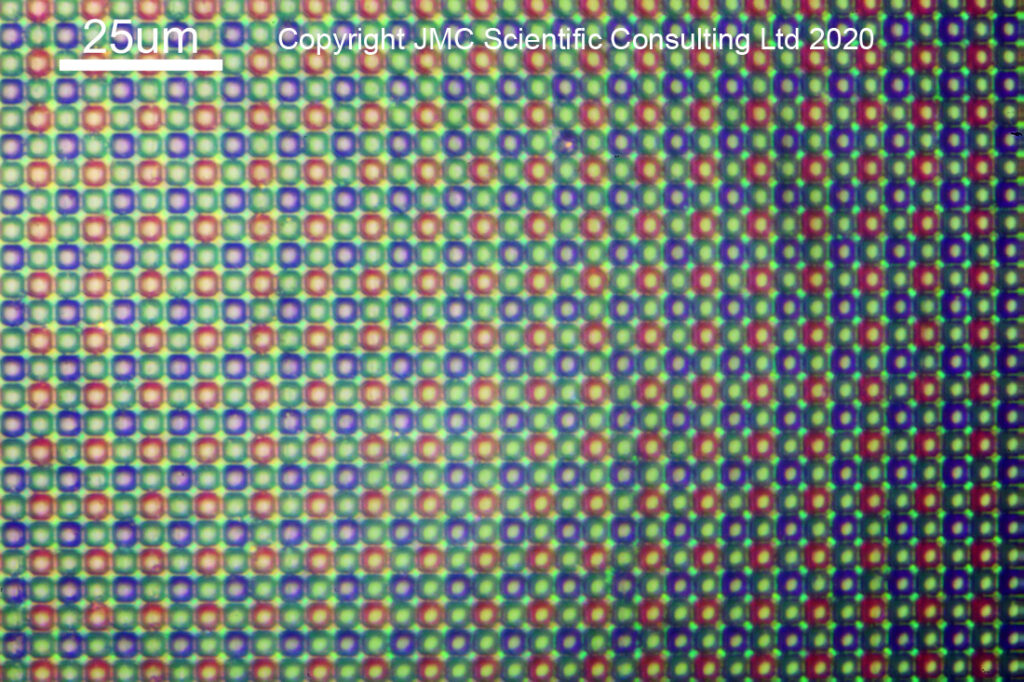
You can see the very neat arrangement of red, green and blue filtered pixels (2 green to 1 red and 1 blue). On top of each coloured region is a microlens. This focuses the incoming light through the coloured filter and into the sensor to be collected. In a conversion to monochrome, these microlenses and the Bayer filter are removed, leaving the bare sensor behind. Here you can see what it looks like as the microlenses start to be removed.
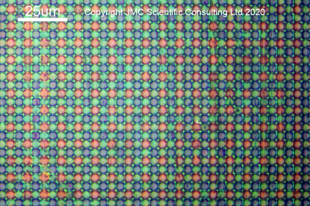
And then, with the microlenses fully removed.
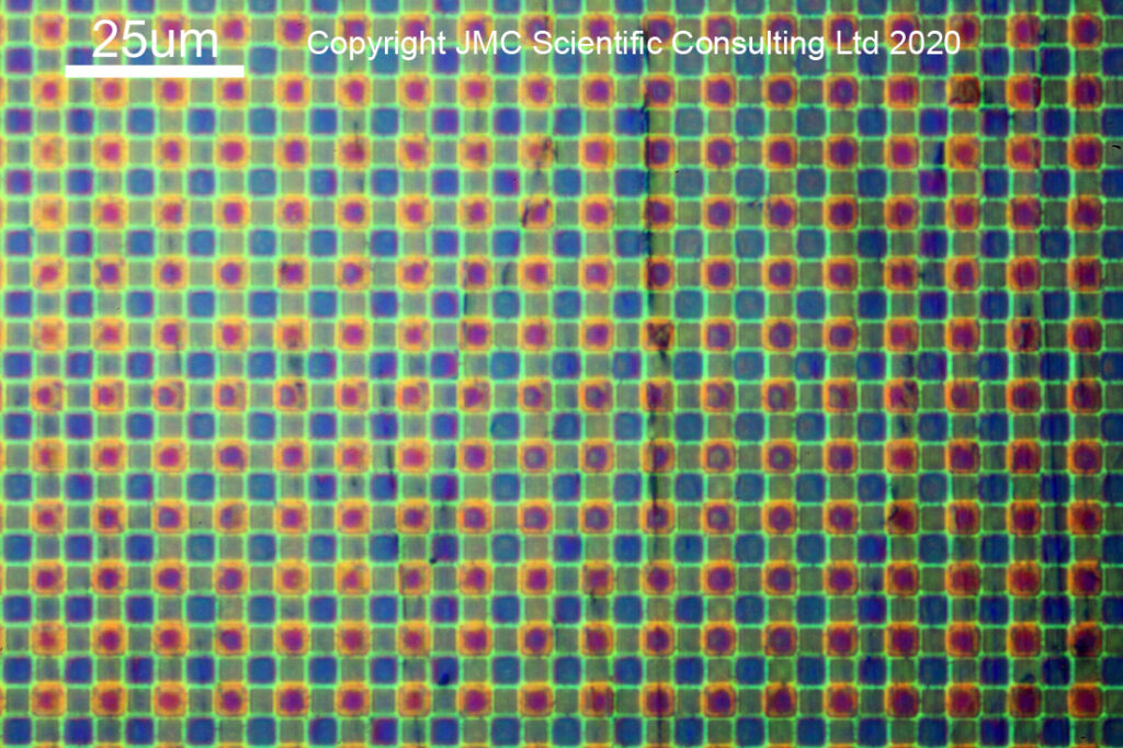
With the microlenses removed, you can now see the coloured squares of the Bayer filter. Oddly enough the green ones look smaller than the red and blue ones, and I’m not quite sure why that would be the case. With the monochrome conversion, this coloured filter layer is also removed, and the bare sensor is revealed.
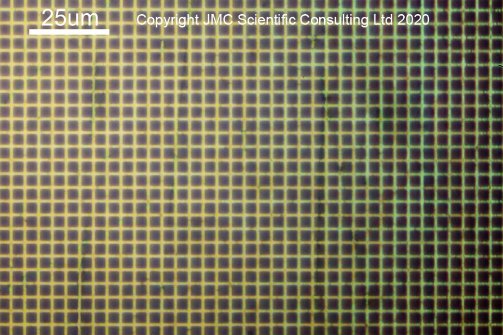
With the monochrome conversion, all trace of the coloured Bayer filter is now gone. It also reveals why the microlenses play an important role in the sensor design. The darker squares are, I believe, the sensitive parts of the pixels. The microlenses gather light from a larger area than the pixel itself, and focus it down into the sensor to be collected. Sensor architecture also plays a significant role in their effectiveness at this task, but that is a story for another day…
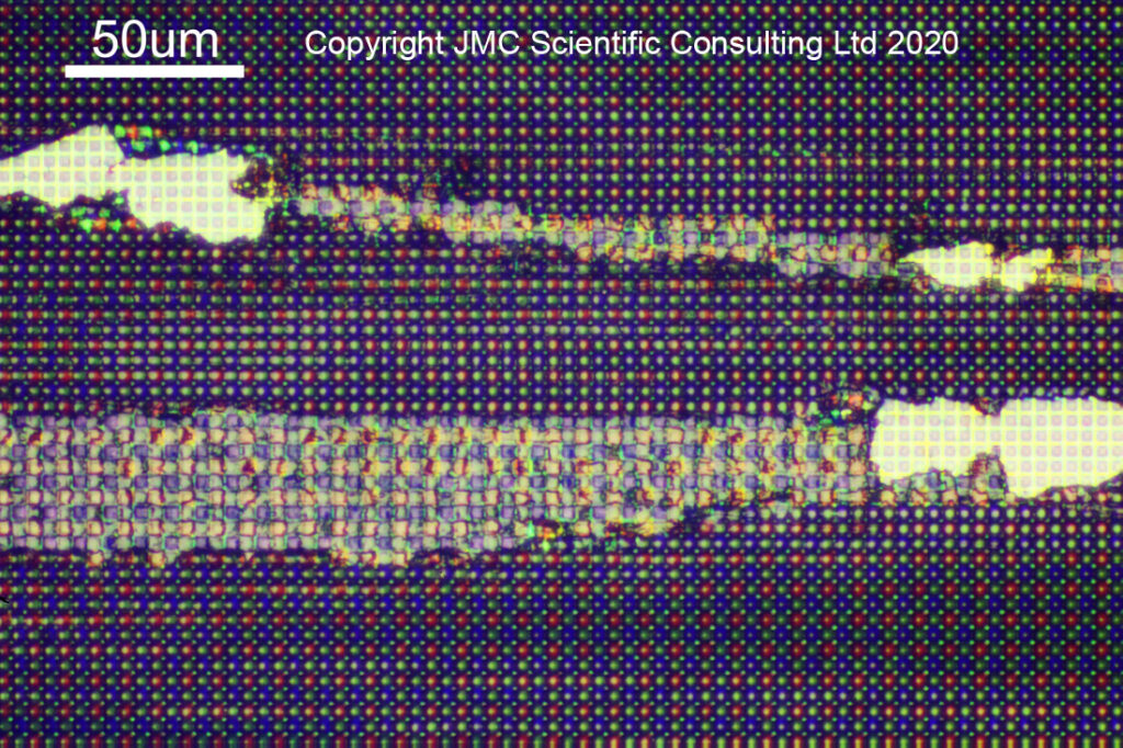
The sensor I had for imaging was damaged, and quite fascinating to look at under the microscope. I found a region where something sharp had been dragged across it, scraping away the microlenses and Bayer filter, revealing the sensor underneath. It enables the different regions to be captured in one image – raw, untouched, sensor with microlenses, microlenses partly removed, microlenses completely removed from the Bayer filter, and bare sensor with the Bayer filter removed – as shown in the image below taken with a 20x Neo objective.
As a quick note for the microscopists amongst you, I used bright field imaging for these images. With this the light is directed down the objective optics, before being reflected back up along the same path. This reduces the image contrast somewhat. The Neo objectives have a path around the edge of the optics for the light to travel, ending up with an image which I suppose is a bit like a dark field transmission image, but I did not use there here as the bright field illumination photos looked nicer.
When you start on a new adventure, it isn’t always clear where you are going to end up. When started with microscopy about 6 months ago, I’d assumed I would be doing transmission imaging. By learning as I go along, I’ve now ended up with a reflection microscope, which has allowed me to visualise what I had theorised about when writing about monochrome camera conversions and UV imaging. As scientists we should always be open to letting the work guide us, in addition to just ‘running the experiment’.
Thank you for reading, and if you’d like to know more about this or any of my other areas of work, I can be reached here.