
As some of you may know, I bought an old and tatty microscope during the recent Covid related lock down, with the aim of restoring it and learning a new skill at the same time. I’ve affectionately called it Project Beater given the state it was in when I bought it, and so far it has been fun to work on. Parts of it were filthy, with grease that was meant to keep everything moving set like glue, so a good cleaning was the order of the day. However when it comes to old equipment, is there such as thing as too much cleaning? Well, as it turns out yes there is……
To expand the capabilities of the microscope I’ve been on the look out for some of the add-ons that were originally advertised for it. One supplier I’d bought something from offered me a reflected light fluorescence setup which would be suitable for the microscope. These are reasonably complex optical components, but the idea is the supply a light to the sample which has been filtered to give a specific range of wavelengths. This then bounces off a dichroic mirror down on to the sample where it causes the sample to fluoresce at a different wavelength. This fluorescence then passes back through the objective and (this is where it is important) back through the dichroic mirror, before reaching the eyepiece. As you can imagine the dichroic mirror is a very important part here, and does the job of reflecting some wavelengths while letting others pass through it.
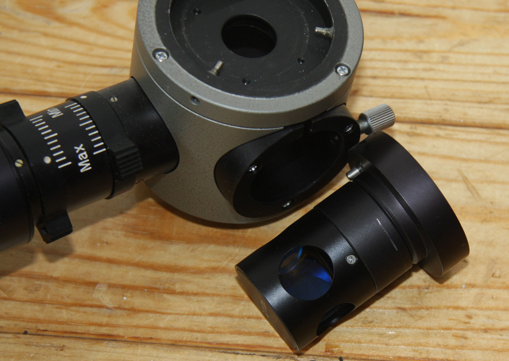
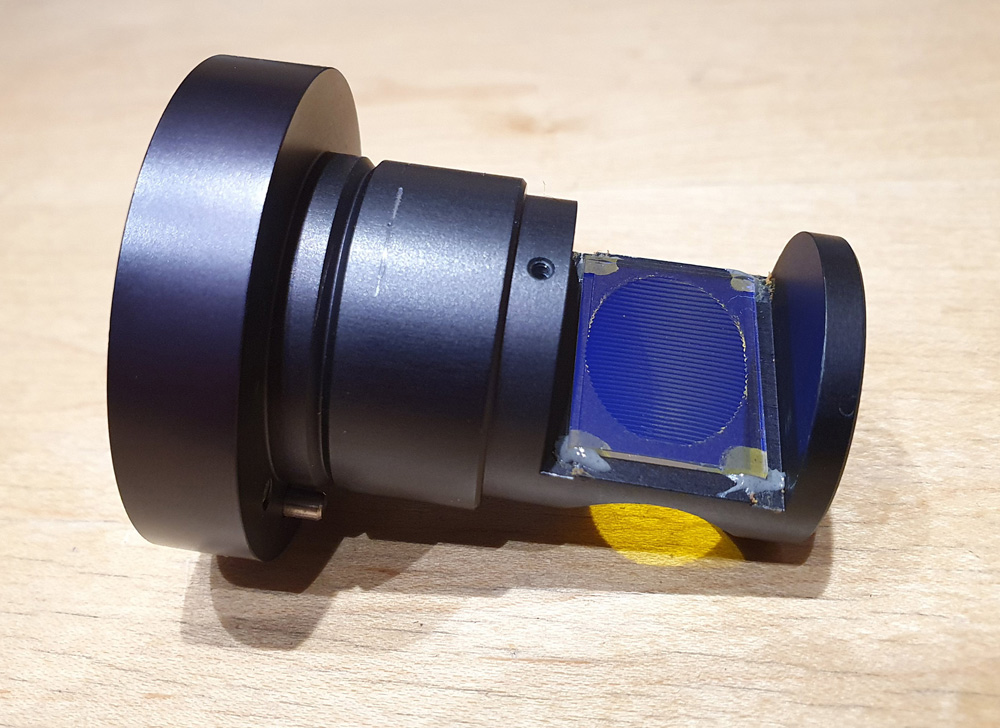
The reflected light fluorescence device comes with removable blocks containing the required filters for fluorescence with certain wavelengths. Mine came a ‘Blue’ dichroic mirror setup, meaning that blue light would hit the sample, and wavelengths longer than about 500nm would pass back through the mirror before going through the orange emission filter and being detected. Here’s a close up of the dichroic mirror block removed from the setup, with the dichroic mirror just visible inside it.
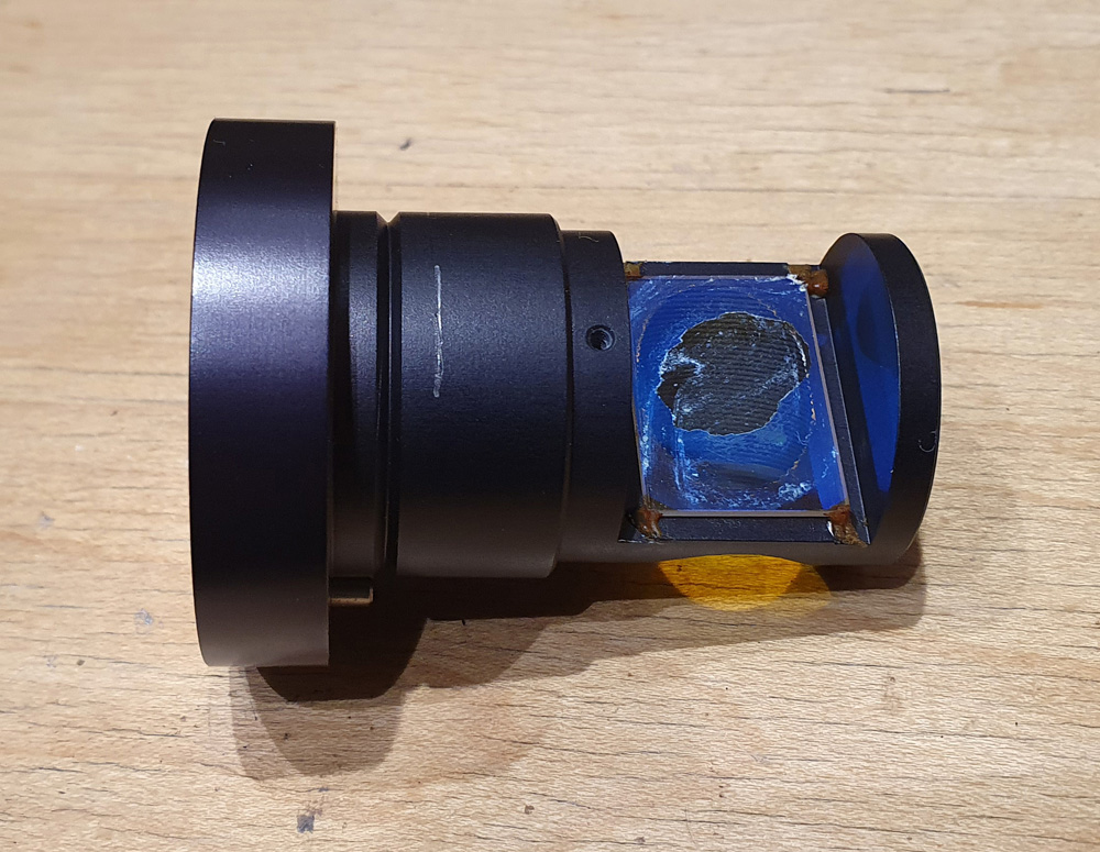
This device is about 40 years years old, and like all optical filters looked like it could do with a bit of clean. However when I started with even the most gentle touch, the coating on dichroic mirror just disintegrated, leaving behind a bare piece of glass, and shower of dichroic coating flakes. This is what it looked like, post ‘cleaning’….
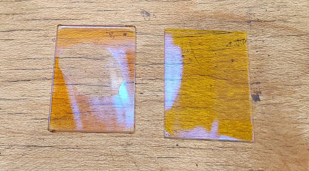
My heart sank. Without this the whole device is useless, and finding another 40 year old mirror block would be, well, ‘challenging’ is one way to put it. So it left me ‘in a bit of a pickle’ (many other choice phrases were used at the time). After I stopped kicking myself for making such a stupid mistake it was time to make a plan and try and salvage the situation. Firstly I checked out Alan Wood’s excellent website on Olympus microscopes (here) and looked through the manual for the reflected light fluorescence device, in which were plots of the transmission curves for the different filter blocks. On my blue filter block, it looked like I needed something which reflected blue light and shorter wavelengths, and let through longer wavelength light. This made sense, as the remainder of the coating on the old filter reflected blue as can be seen in the picture above. To try and find a suitable filter my first port of call was UQG Optics, who I’ve bought a few parts from before. They had a few different dichroic filters, and their Dichroic Yellow looked like a pretty close match. After providing them with the size for the filter based on the one in the block, they were able to cut a 50mm square one down for me. Visual comparison of the 2 filters showed they both reflected blue light, and were a similar (but not identical) colour for transmitted light.
A more scientific test was to measure transmission of the filters when held at 45 degrees (this is important as dichroic filters change their optical properties as the angle the light hits them varies, and it’ll be hitting at 45 degrees when mounted in the block). This gave the following;
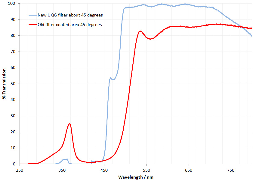
As expected the new replacement filter was similar, but not identical to the old filter, with a lower cutoff for transmission and blocking more of the UV. Reflection from the surfaces at 45 degrees was also measured, but that was just a relative measure as I don’t have a specular reflection standard. This again showed they were similar but not identical, with the new filter starting to reflect below 500nm, while the old one reflected below about 530nm. These values correlated well with the measured transmission curves, which is as expected.
What does this difference between them mean? The new filter lets through slightly shorter wavelength light than the old one. Therefore I’ll need to slightly adjust the wavelength of the excitation filter, or risk just losing some of the excitation light rather than having it reflected to the target. Not the end of the world, and at least gives me something to have a play with. The old filter also bled quite a lot of UV, although this could have been due to degradation of the filter because of its age. The new filter didn’t leak UV as much, meaning more could be reflected on to the sample depending on which excitation filter is used. To mount the new filter a small blob a glue was applied to each corner as with the old one.
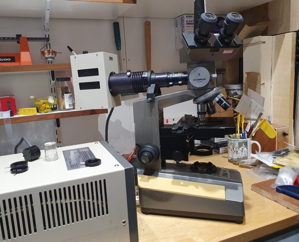
The next step was to get the 100W mercury xenon lamp going, so I could start to do some fluorescence microscopy (this lamp will be the subject of another post in the future). Here it is all setup on top of the microscope.
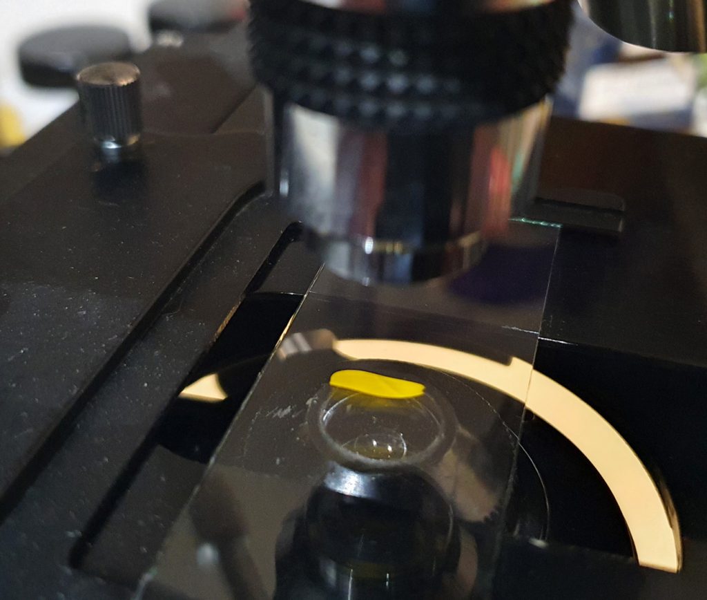
I chose a UG5 excitation filter as I was mainly interested in looking at UV induced fluorescence. The subject was a petal from a Ragwort flower as it should show some nice fluorescence.
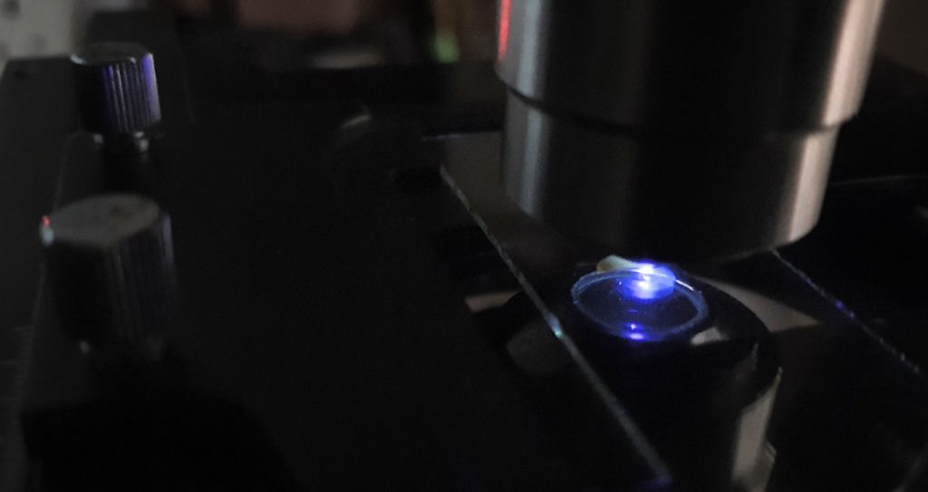
With the lights out and the mercury xenon lamp on, you can see the light hitting the sample.
Looking through the 20x Olympus SPlan objective I could see the following (captured using a camera phone through the eyepiece).
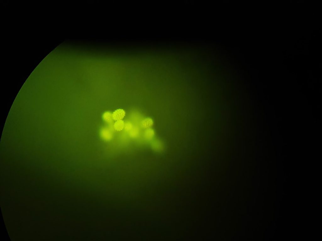
And cropping the original image, the spiky ‘pineapple’ shaped pollen grains can be seen fluorescing.
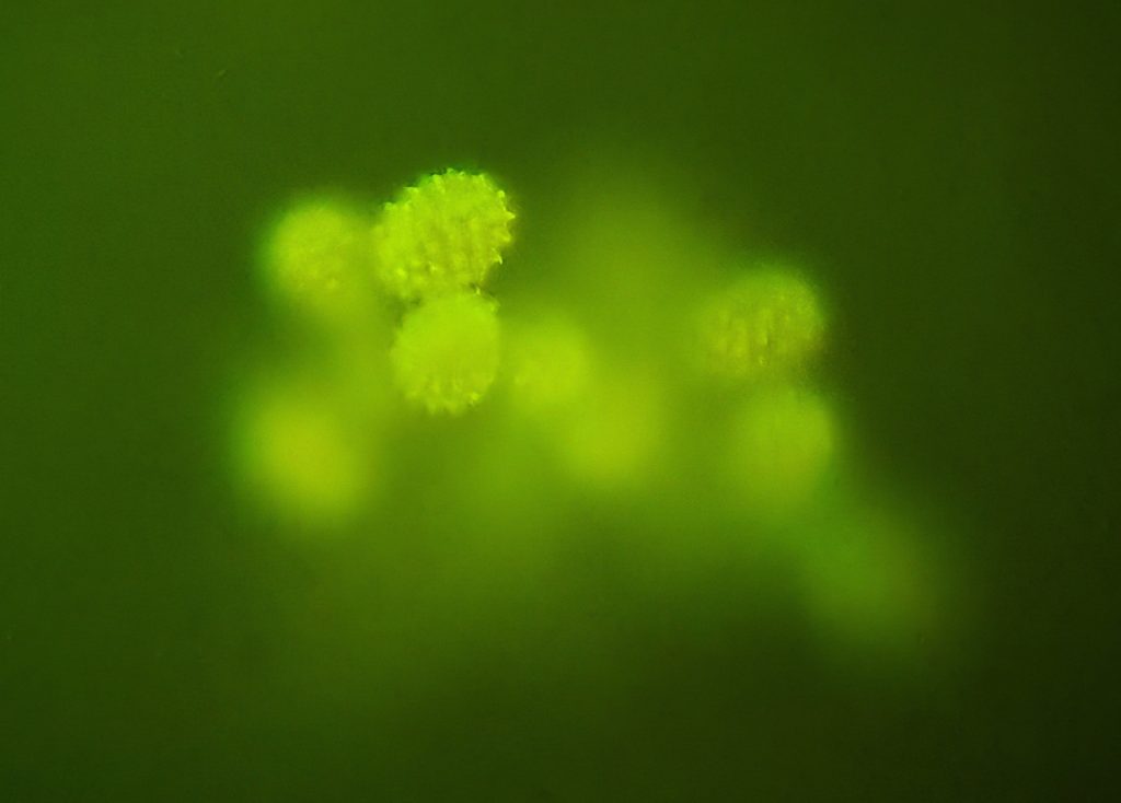
Remember that this is a single image with no focus stacking, so not all the pollen grains are in focus. However it shows the setup is working.
What have I learnt here? If something looks a little dirty, stop and think before cleaning it, especially when it is a bit older. If I find any other filter blocks for this, the dichroic mirror will be left well alone. The replacement filter was close in properties to but not the same as the original one. This will have a little bit of an effect on the usability, but hopefully not huge amount. After a bit more of a hunt I’ve tracked down what would be a closer match to the original dichroic mirror, so I’ll keep a note of that if this one doesn’t work out. Overall though, as scientists we shouldn’t be afraid to experiment. Yes, some things we do wont work out as expected and if that happens, step back, take a deep breath, assess the situation and plan the next step. Most importantly, don’t be afraid to keep experimenting.
Thanks for reading, and if you want to know more about this or my other work, you can reach me through my Contact Me page.