Working in the area of UV imaging and microscopy gives me 2 options. Firstly, win the lottery (or sell a kidney or two) so I can afford to buy new equipment. Secondly, try and hunt down older equipment which can be re-used. Given that I’m quite attached to my kidneys (literally) and that unfortunately that lottery win still evades me, that leaves the second option as being the preferred route. Even this route presents significant challenges though. Very often these piece of equipment were made in very small numbers, most dealers have never even seen or heard of them, and some are well over 50 years old now so tracking down information on them is extremely difficult. Today, I have a little bit of an update on a post I shared earlier in 2020, and also a new historical Leitz objective that I’ve tracked down.
Firstly, the update. Earlier this year I shared a post which talked about a 300x reflecting objective lens – here. This lens is based on a mirror system rather than refractive optics, and is suitable for UV, visible and IR imaging. I bought it as a bit of a collectors items really, and while I’d love to use it some day, it’s going to take some pretty complex work to make that happen, as the tube length it has is much longer than that microscope I have at the moment. While I did find a mention of what I thought was it, in a catalogue from 1967, I didn’t know any more about it.
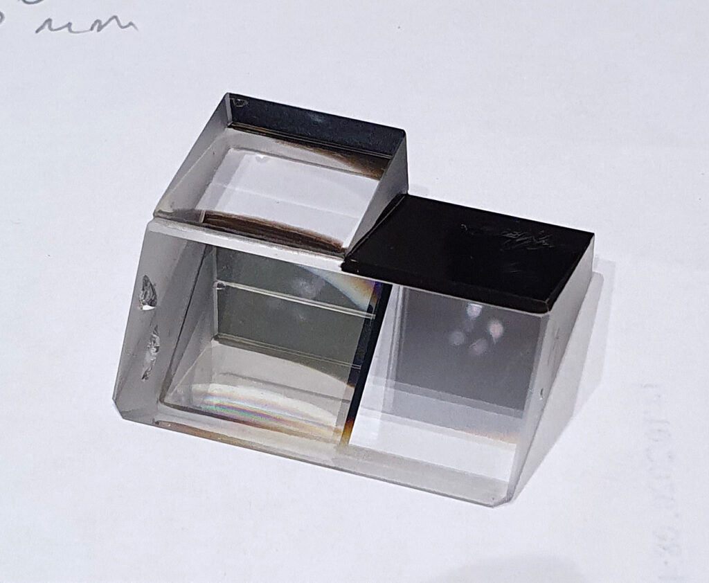
Fast forward about 6 months, and I was talking with a dealer in Sweden and he mentioned that he had a couple of interesting items. One was a Leitz microscope condenser which had the markings “Glyc Q” on it, and the other a lens which had “Quarzglas” and “Glyz” on it. Now these make my ears prick up a bit as the use of glycerine (marked as “Glyc” or “Glyz”) often implies they were designed for use with ultraviolet light, as does “Quarzglas” (as quartz is UV transparent). So after a quick discussion they were on their way over to me.
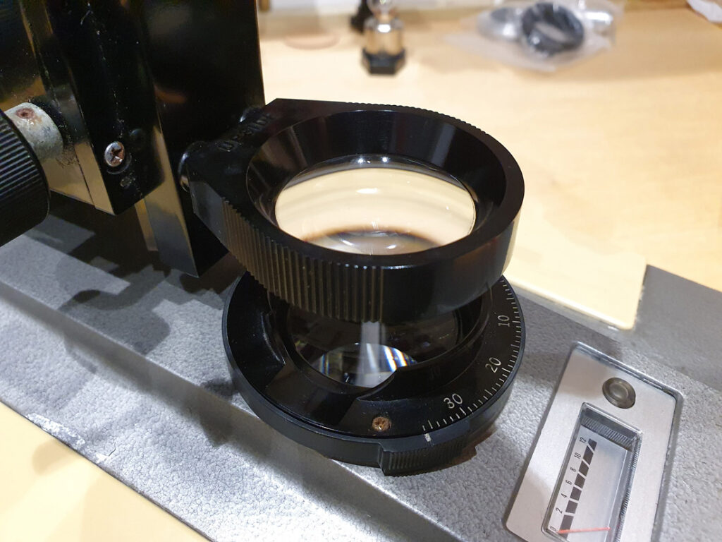
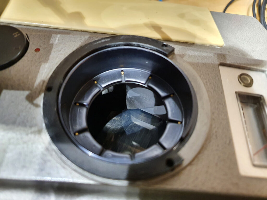
I’ll come back to the objective lens with “Quarzglas” in a minute, and cover the condenser first. The 300x reflective objective I already have was pictured in the catalogue alongside a couple of small condensers (see below).
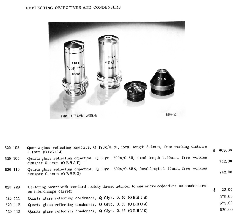
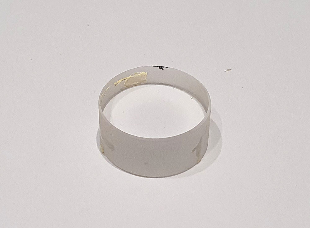
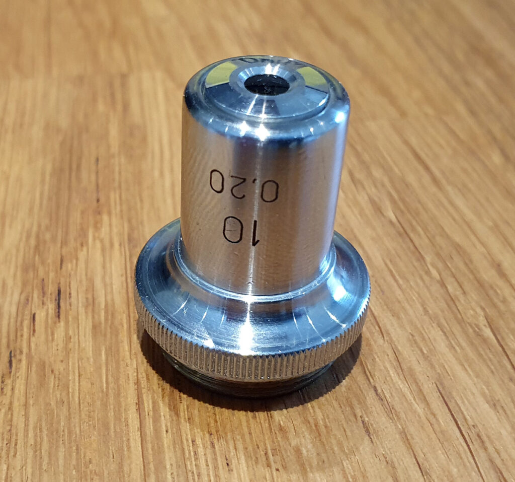
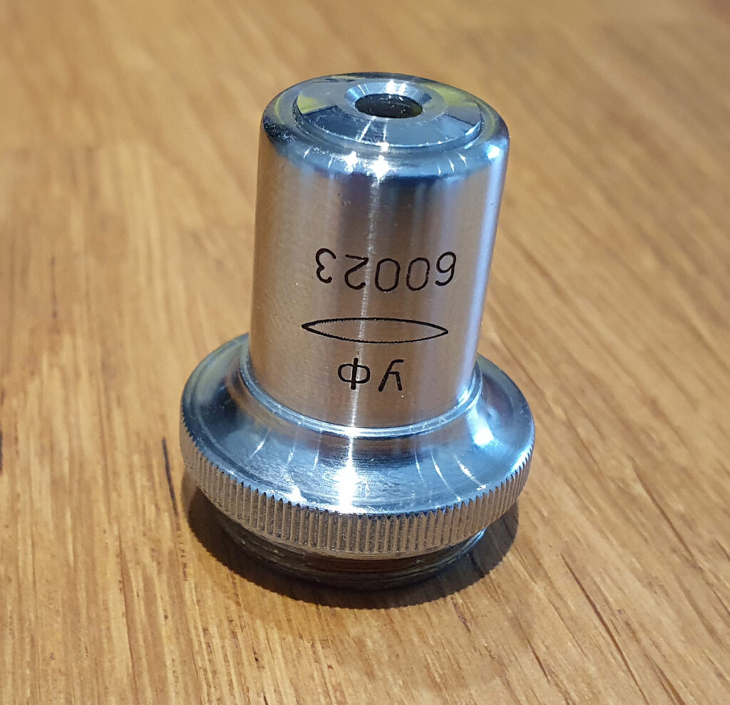
Being quartz glass the reflecting condensers these should also be suitable for UV work. The one I have is one of the 0.6 NA ones, mounted in a Leitz holder.
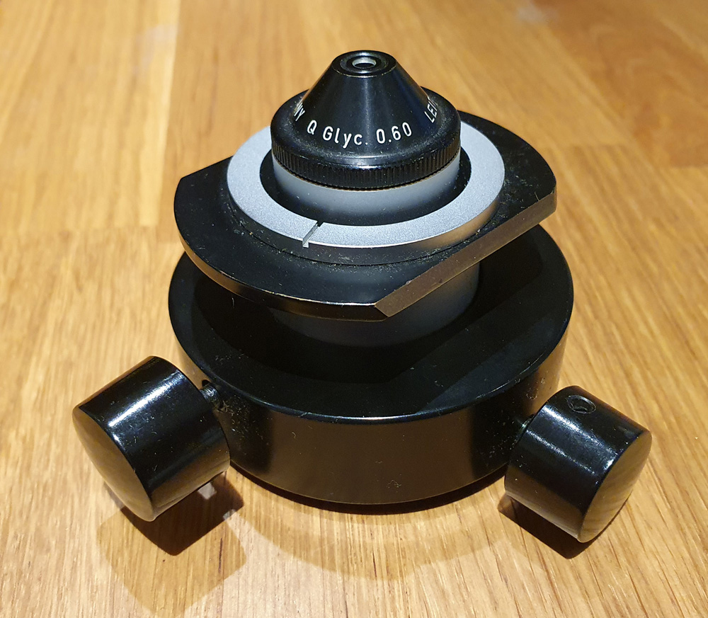
While the wording on the condenser is not exactly like the one in the brochure, I think this is the same one as advertised. The difference is probably down to being different batch or production run, as I’ve seen small differences like this before.
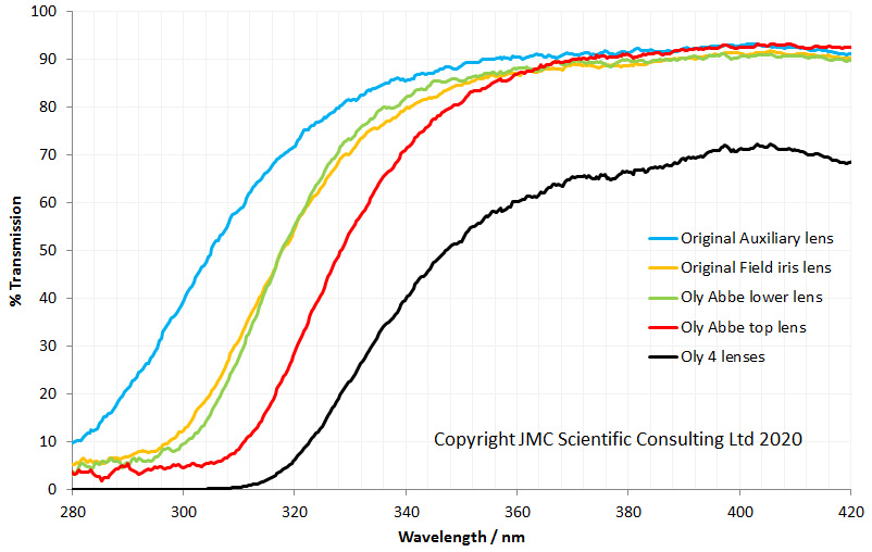
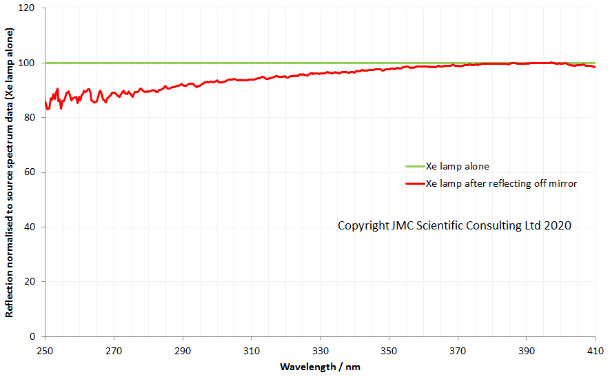
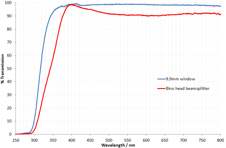
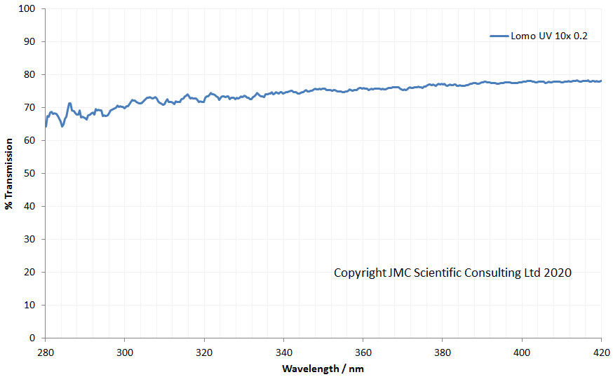
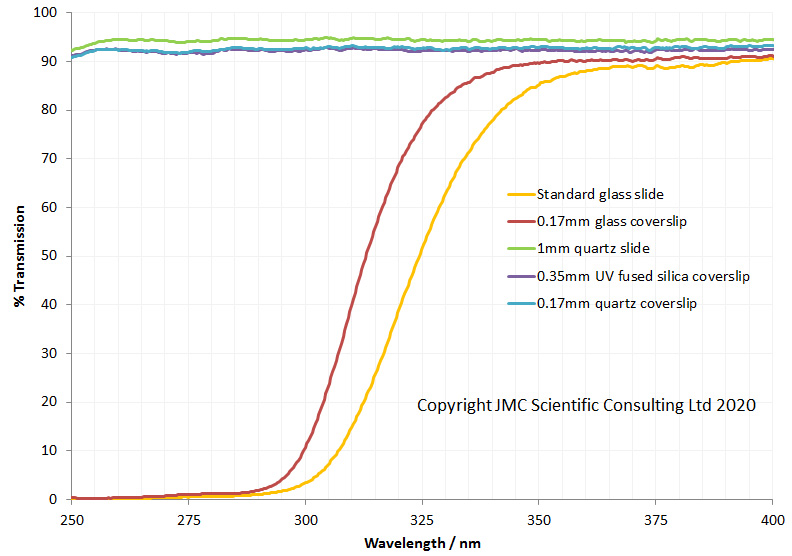
How does the transmission of this condenser look. I measured transmission between 280nm and 420nm and got the following.
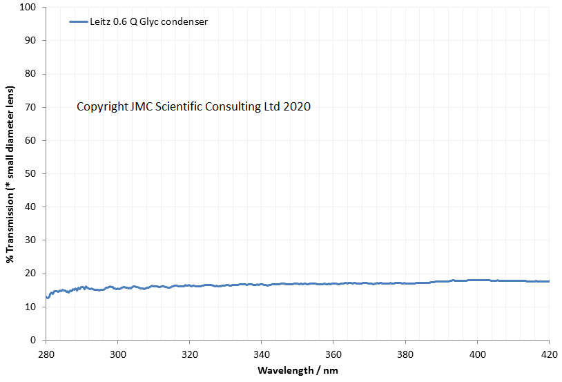
At first glance the transmission of the condenser doesn’t look great. However it should be kept in mind that the light gathering part of the condenser is quite small, smaller than the diameter of the light beam in the my transmission measurement setup, therefore some of the incoming light is not hitting the open part of the condenser. This of course limits the max transmission possible. The key thing here is that there is no significant drop between 420nm and 280nm, indicating that it has good transmission in the short wavelength UV region, and as such would be suitable for UVA and UVB imaging. Hurrah.
As a slight aside I also found out a little more about the 300x objective I have. In a paper from from 1964 (Klaus Weber, “New developments in microscopes at Leitz”, Applied Optics, 1964, 3(9), 1045-1048), it describes the mirror objectives as follows; ” The mirror objectives expand the application of microscopes into an additional spectral range; the objective Q 170/0.50 and the glycerin immersion Q Glyc 300/0.85 are suitable for a spectral range of from 2200A [220nm] to 7000A [700nm]; and they are fully achromatic. Suitable condensers are also provided. Mirror objectives consist of spherical mirrors on quartz bodies. The main characteristics of the Leitz mirror objectives are the very small central zone (only 5% of the pupil size), thus guaranteeing very good contrast even for extremely fine object structures. The special type Q Glyc 300/0.85 s, which has a somewhat reduced light transmitting capacity, produces maximum contrast even for finest structure elements over the entire spectral range. It is particularly suitable for microphotometry.”. My 300x one is marked with the ‘S’ on the end, indicating is is one of the slightly higher contrast ones.
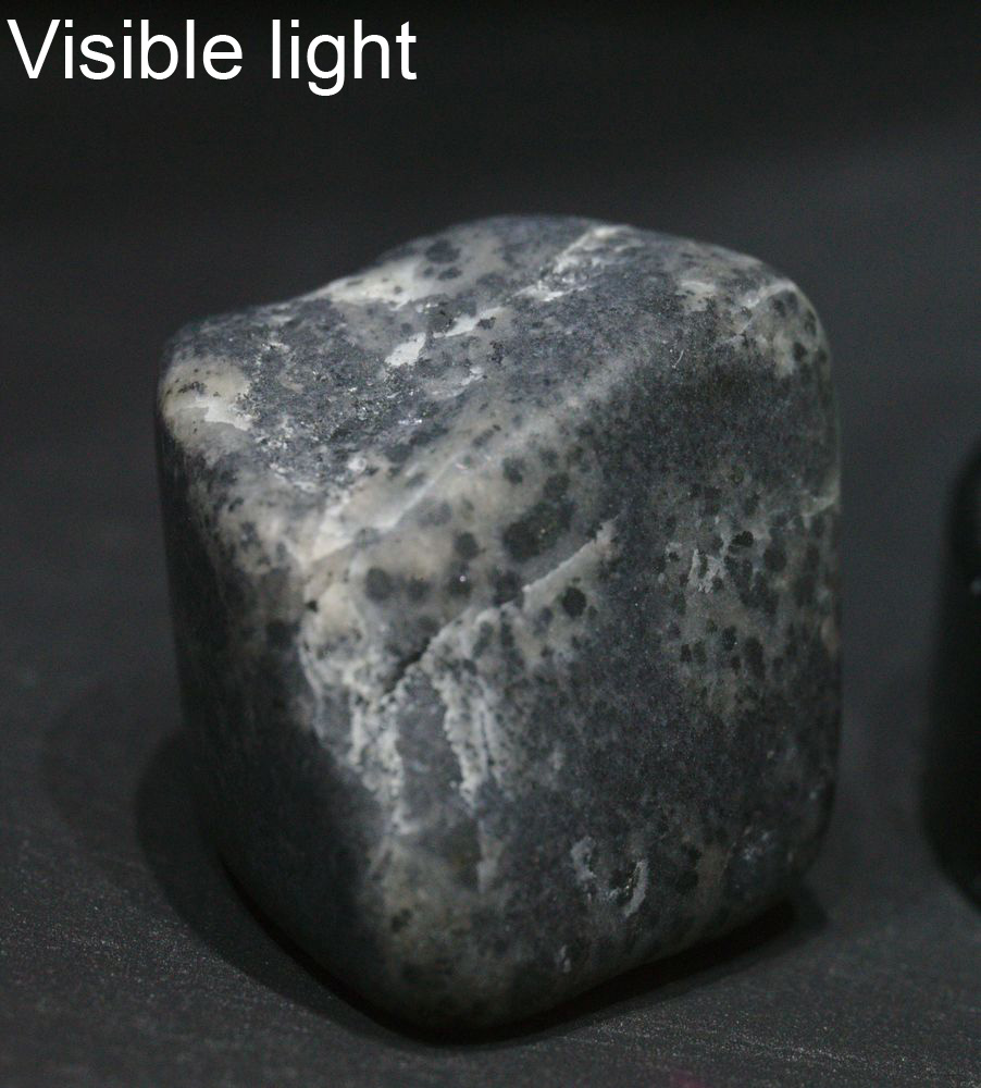
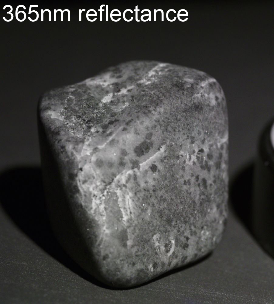
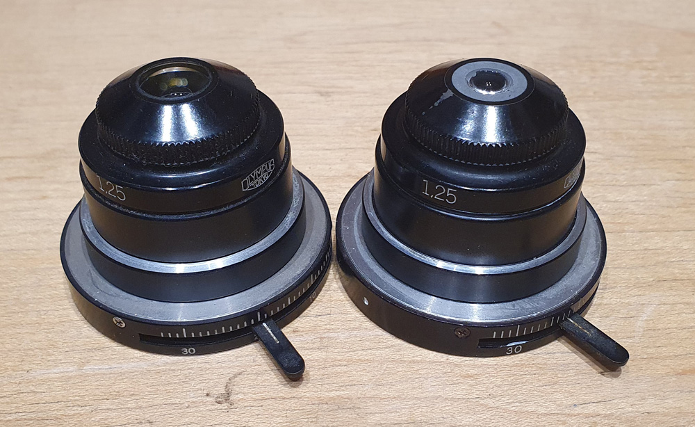
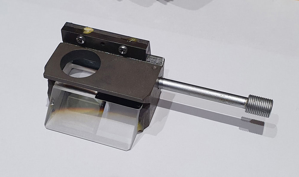
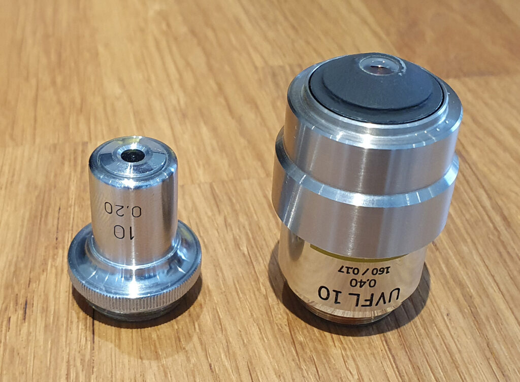
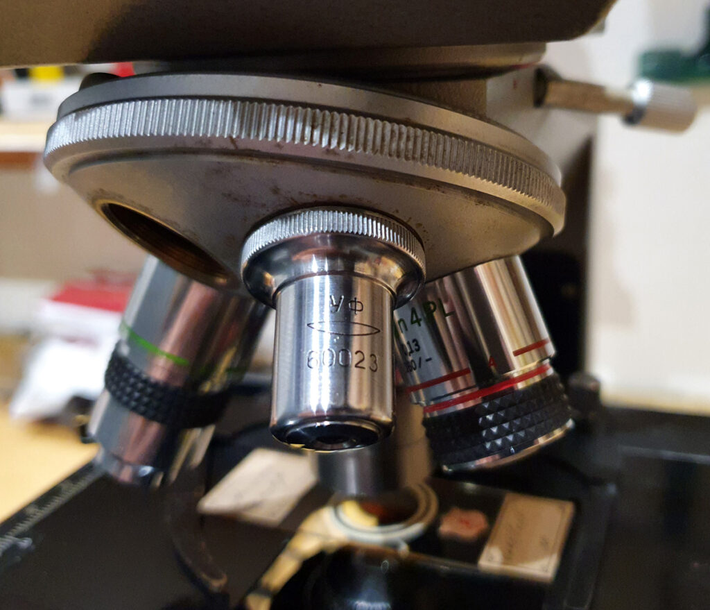
Now for the second item that arrived. This is an objective lens with a 50x magnification and is shown below.
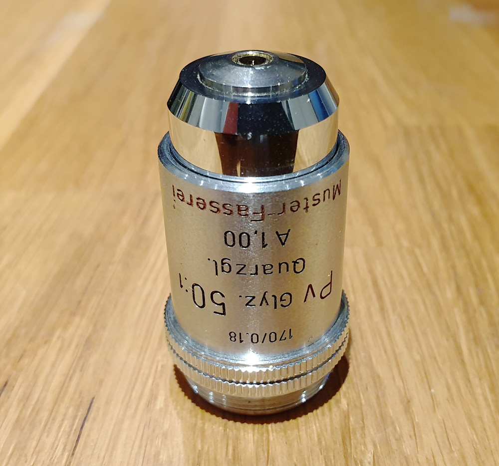
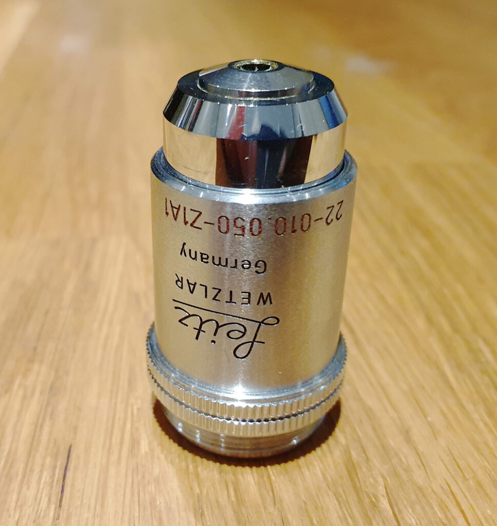
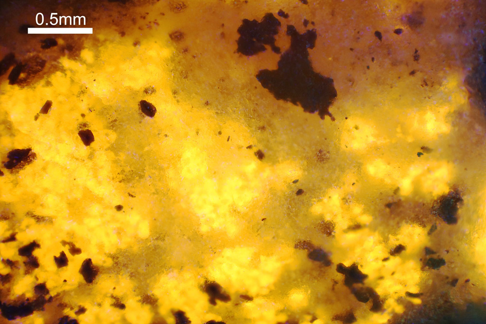
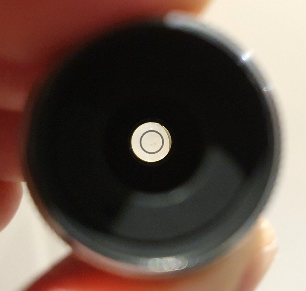
There’s a lot going on on the label, so what does it all mean. ‘170/0.18’ means it is designed for a 170mm tube length, and a 0.18mm thick coverslip. So far, this is fairly standard. ‘Pv Glyz. 50:1’ means it is for phase contrast (Pv), meant to be used with glycerine as an immersion fluid, is 50x magnification. It has an NA of 1.00 (‘A 1,00’). The phase ring can be seen in the photo below.
The next line on the lens is really interesting – ‘Quarzgl.’ as this should indicate it is quartz so should in theory have good UV transmission. After that, the ‘A 1,00’ has already been discussed. Next we have ‘Muster-Fasserei’ in red. This is an odd one, and not something I have seen before. Talking with a couple of optics expert the overall consensus is that this was a prototype or manufacturing pattern for this lens design, making it a rather interesting piece. While Leitz did make a few refractive optics for UV work (which I have), the ones I have seen so far were not phase contrast ones, again potentially adding to the uniqueness of this one.
What about the history of this 50x lens, what was it designed for? This proved to be a little harder to figure out. I eventually found reference to it in a Leitz document “Image-forming and illuminating systems of the microscope”, where it showed the following (in the line for Pv Glyc 50);
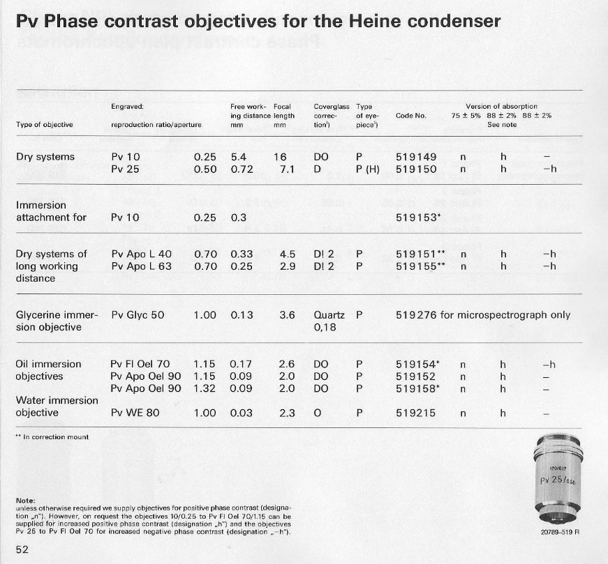
This seems to suggest that it actually wasn’t for use on a normal microscope, but rather a microspectrograph. So far I have found a couple of references to Leitz microspectrographs and microspectrometers from approximately the era of this lens, but nothing that specifically mentions this lens yet, so for now it remains a bit of an enigma. In the document above, the coverglass is given as being Quartz rather than glass, which explains the ‘Quarzgl’ on the barrel of the objective.
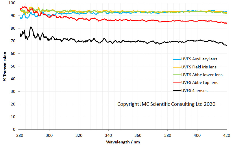
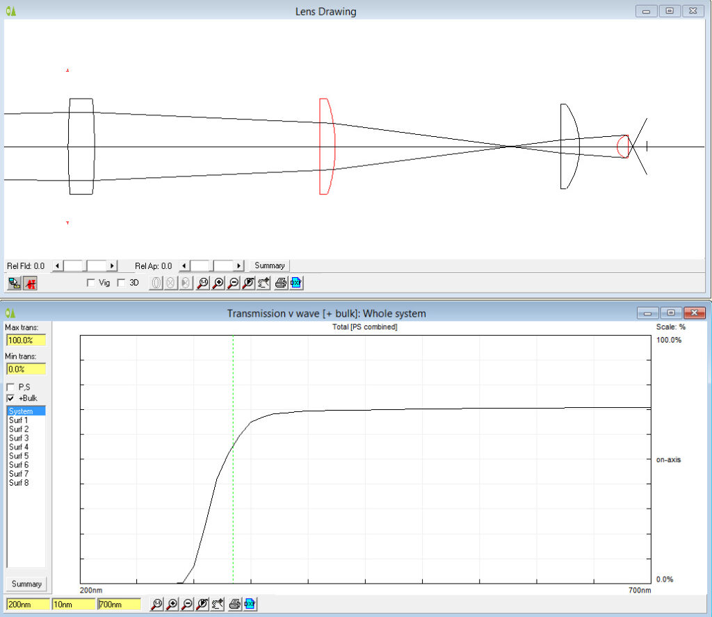
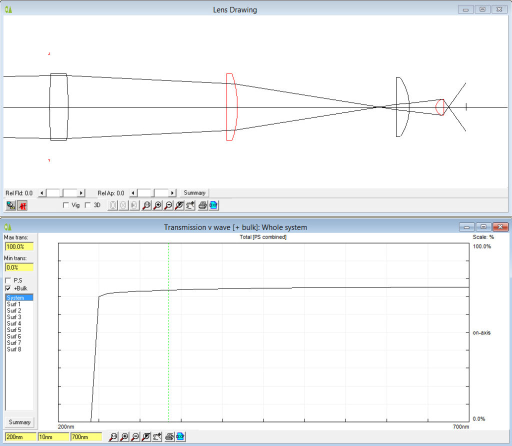
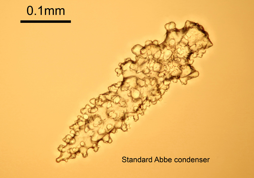
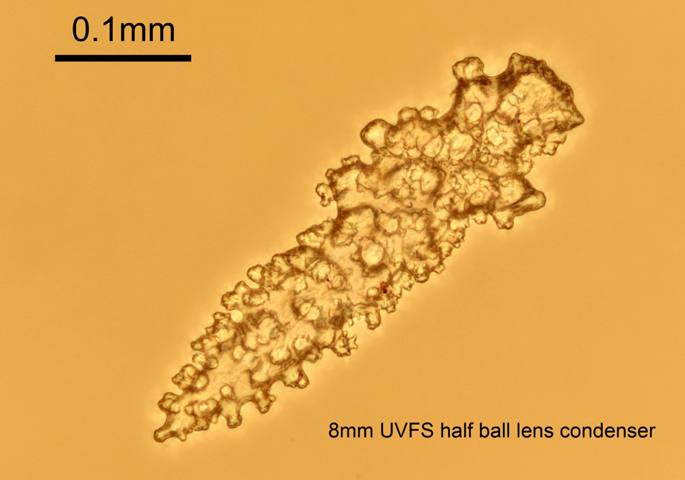
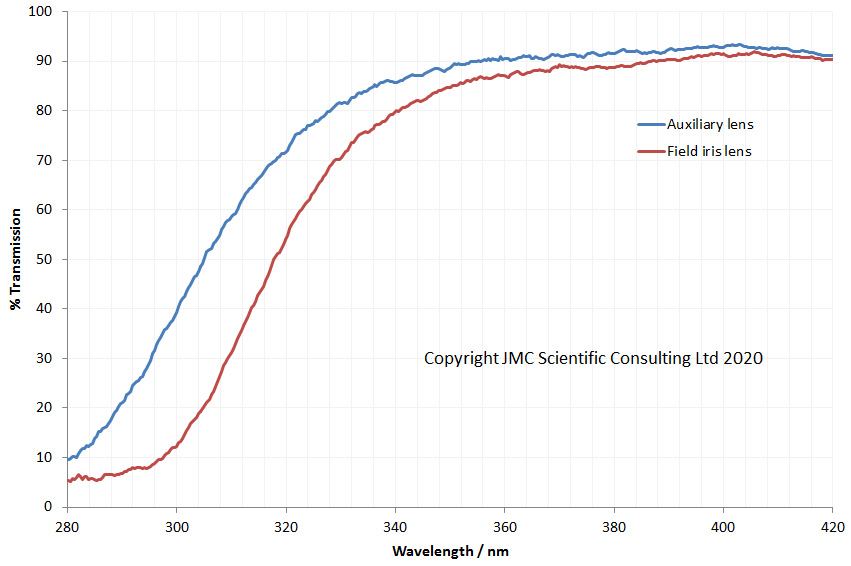
As with the 0.6 condenser above, I measured the transmission spectrum through this objective and got the following.
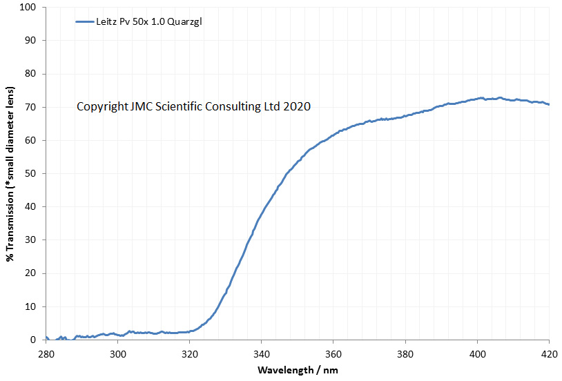
Hhhmmm, this is where things stopped going to plan. As with the 0.6 condenser, this objective is relatively small diameter, so the light source is probably being clipped slightly by the objective, which limits the maximum signal I am measuring. However unlike the 0.6 condenser, the objective is blocking the light below 320nm. Not good, and means it wont be any use for UVB imaging. This is a bit odd, as it has ‘Quarzgl’ on the objective lens barrel, and it should have better UV transmission based on that. Does it have a glass element in there in addition to some quartz ones? Does it have coatings on the lenses or adhesives between them? If it is a mock up, pre-production lens, have they just used glass instead of quartz? I shall probably never know the answer to the last question, unless I ever manage to find another one to compare it with. I shall get some images using it once my glycerine arrives, so for now it is just a technical assessment.
Tracking down old optics has been a fascinating part of my UV imaging research. Often there is very little information on these items, as when they were made they were done so in very small numbers. As with all research the road to knowledge is not always a smooth one, as is the case with the objective lens described above. Sometimes what we thought was the case proves not to be so. This is the very nature of research though, and we must take the rough with the smooth. We should not see it just as a negative – if everything we did was right, how can we learn anything? Very often I have seen data which didn’t fit the hypothesis discounted, with every effort made to discredit it, rather than have someone ask the awkward question “Was the original hypothesis right?”. As scientists we should never be afraid of that question, and always be ready to ask it of our own work as well as that of others. Thank you for reading, and if you’d like to know more about this or any other aspect of my work, you can reach me here.