Quick update today. Always nice to see my work getting recognized. One of my UVB (313nm) diatom microscope images has been selected as the July 2022 cover image for the site amateurmicrography.net. Here’s the image.
313nm diatom image, cover shot for July 2022 on the Amateur micrography site
The Amateur Micrography page links through to the Photomacrography forum which has some of the best macro and micro imagers from around the world, and is well worth checking out if you have a minute.
This is a bit of technical update post, as it covers something I wasn’t aware of before, which may be of interest to other microscopists. A few days ago, I was doing some work with an old 170x Leitz Q NA 0.5 reflecting objective (see here) and noticed that when the aperture of the condenser was closed right down I got a darkfield image, with a black background. This got me wondering whether it would work with other reflecting objectives, and whether it was possible to use this technique to get darkfield images in the UVB region at 313nm (something I previously couldn’t attempt as I don’t have a quartz darkfield condenser). This post gives and update to that work.
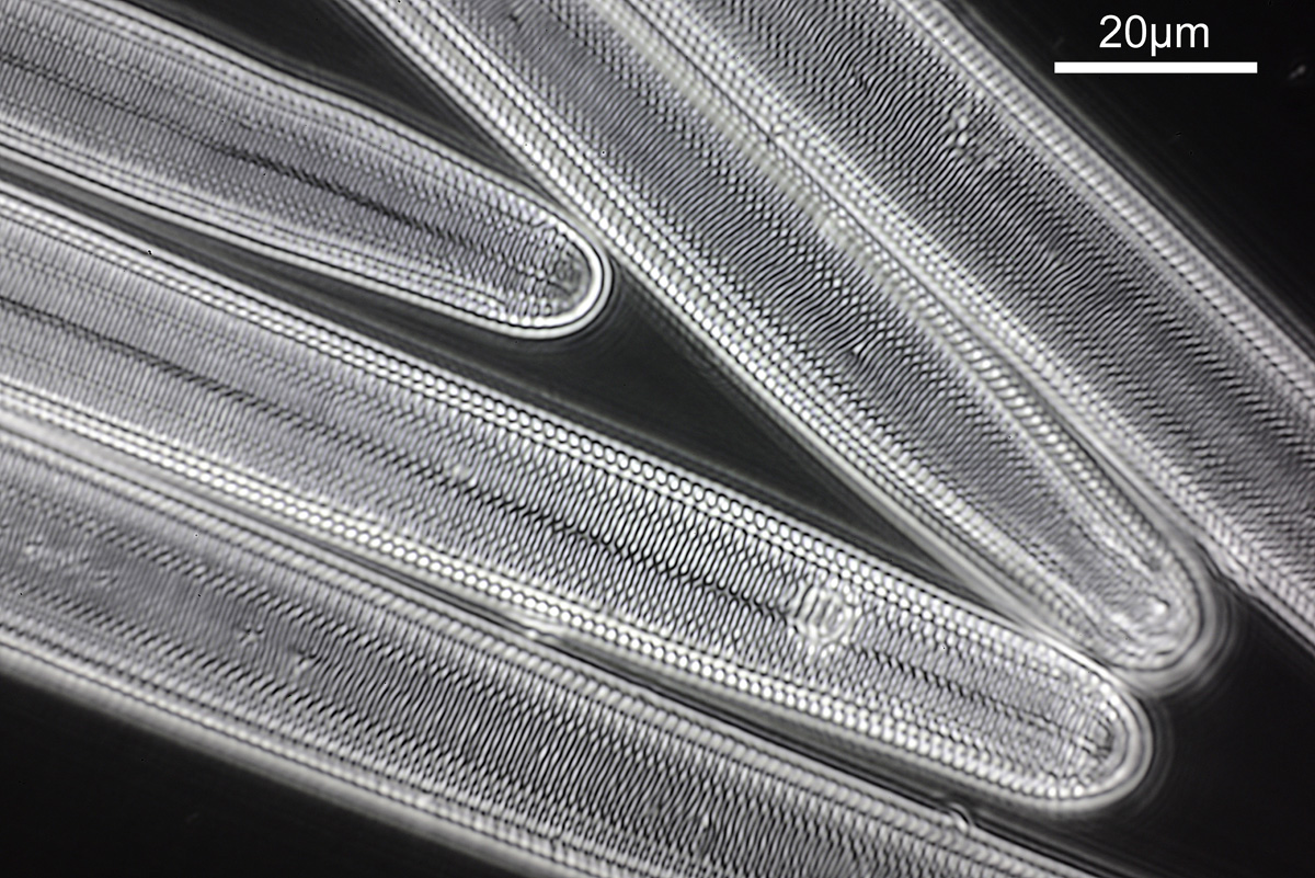
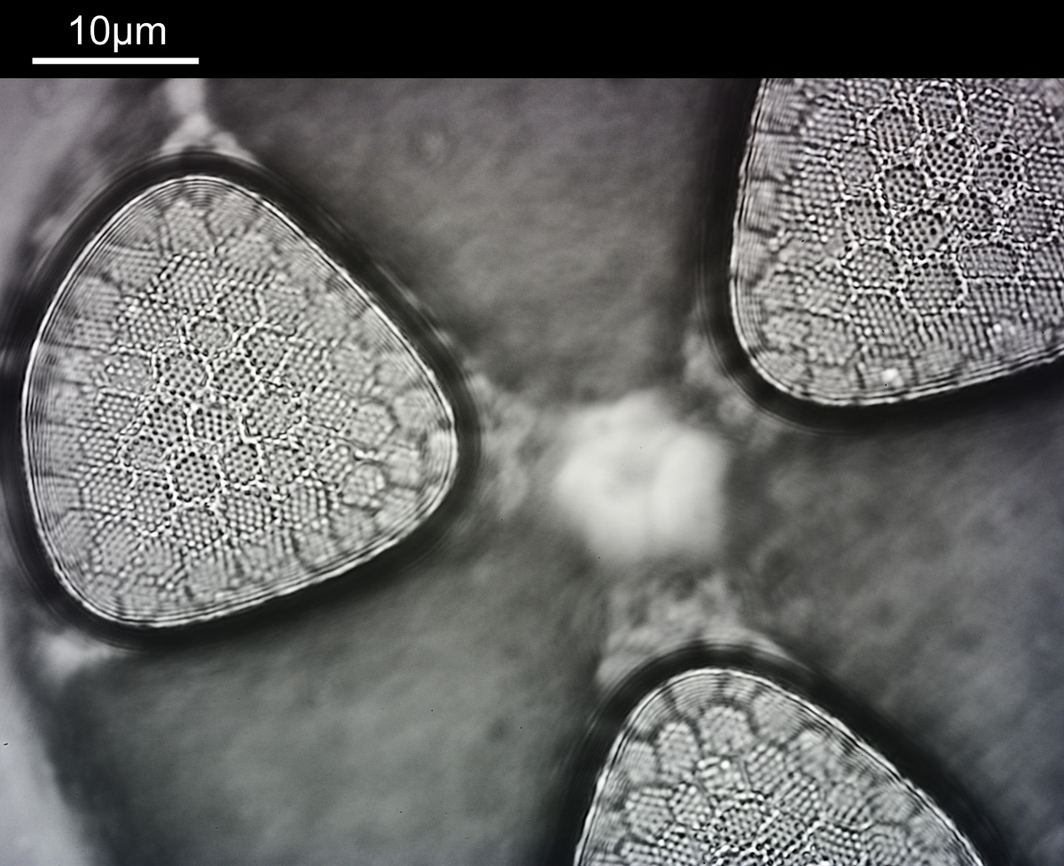
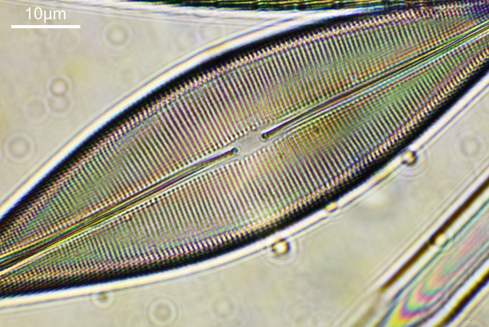
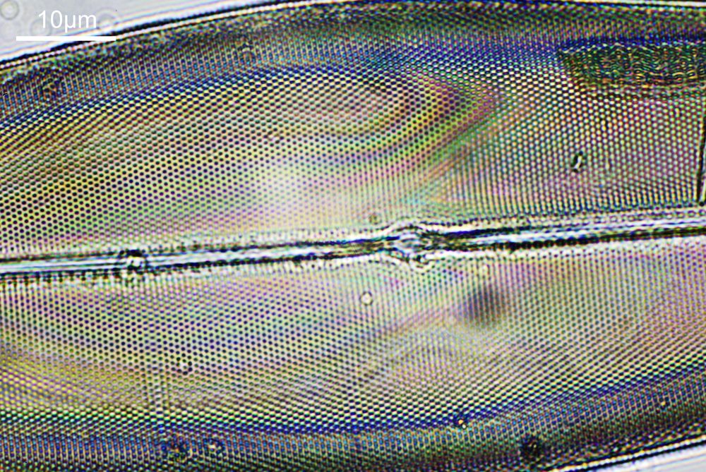
As a subject for imaging I chose the diatom slide which I’d had prepared using quartz slide and coverslip which I have been using for imaging at 313nm (examples here). Rather than use the 170x Leitz reflecting objective, which wasn’t designed for a microscope with a tube length like mine, I used a 15x Edmund Optics NA 0.28 reflecting objective. The condenser was my vintage Zeiss quartz one. With the condenser iris closed right down, imaging at 313nm, I got the following image of one of the diatoms on the slide.
Darkfield image of a diatom at 313nm using an Edmund Optics 15x reflecting objective
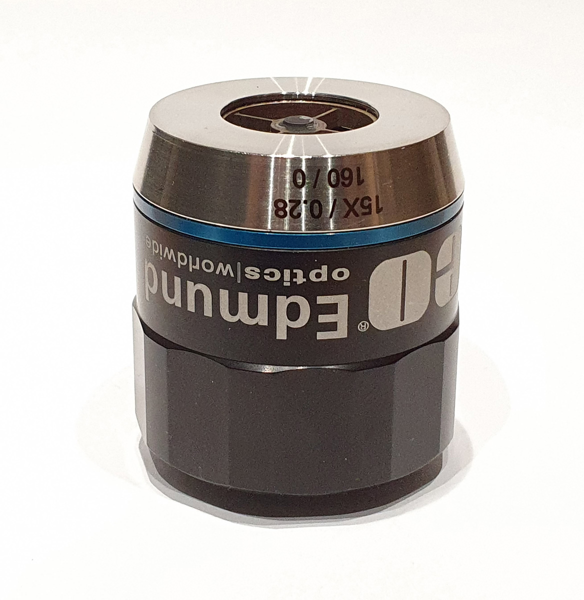
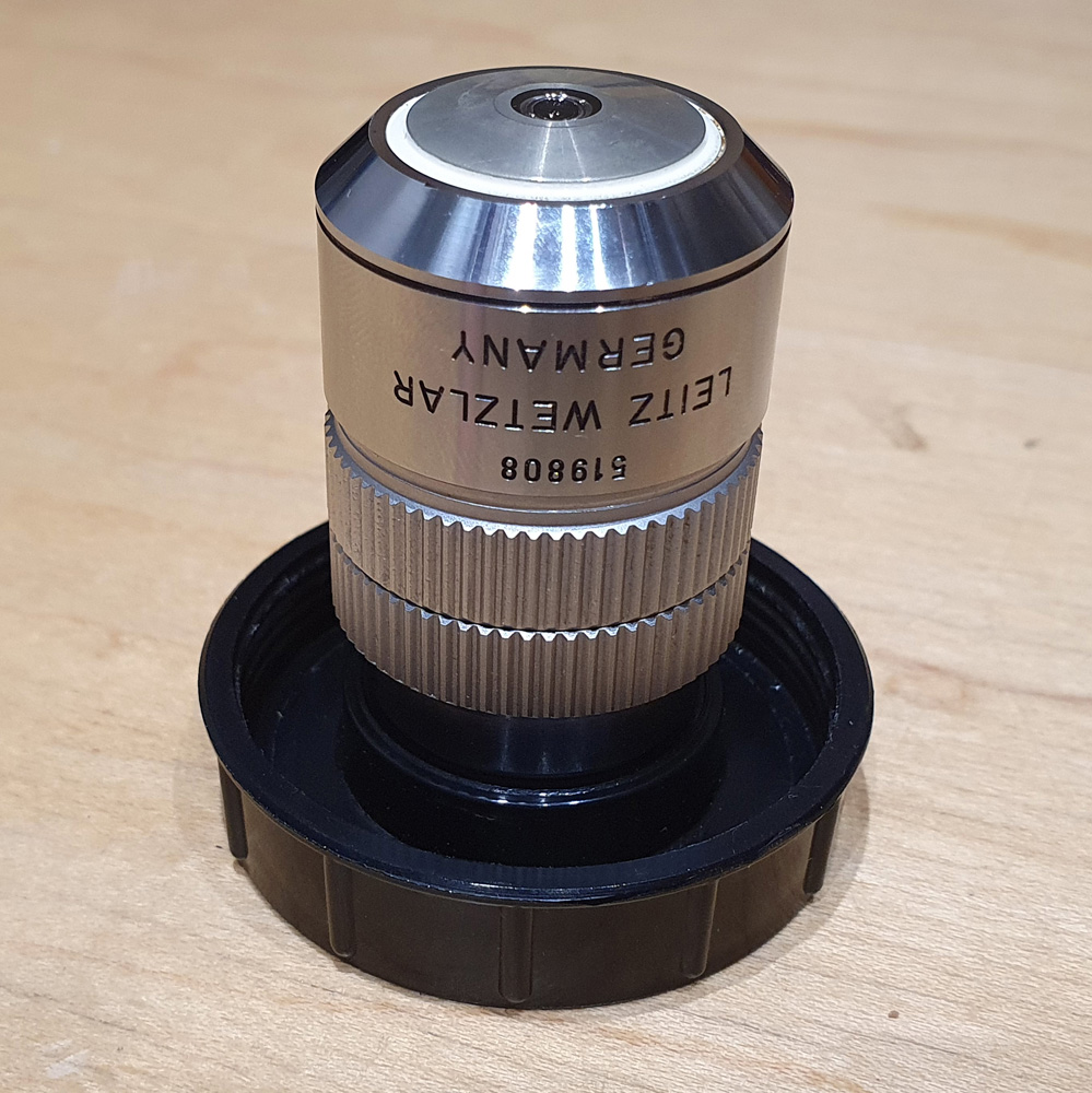
By closing the iris on the condenser right down it does indeed produce a nice darkfield image. By using the quartz condenser and slide, and combining this with a mirror objective it was possible to create a darkfield image in the UVB region at 313nm, something which I hadn’t previously thought possible with the equipment I currently have. For the fellow optics geeks out there, here’s a picture of the objective.
Edmund Optics 15x NA 0.28 reflecting objective
Sometimes it is worth doing experiments just to see what will happen, as the results can be unexpected and open up new possibilities. So, don’t be afraid to experiment. As always thanks for reading, and if you’d like to know more, I can be reached here.
Ok, perhaps not the catchiest title for today’s post. However, it’s an unusual post. When you were young, like me, I presume there were things you were told not to do – “don’t grab stuff out of a hot oven without gloves”, “don’t charge up the cat with static electricity by stroking it for 5 minutes”, etc, etc. Of course, I often did things anyway, although to be fair I never did grab stuff from a hot oven. The objective used was most definitely not designed to be used in this way and would have fallen into the ‘don’t try this’ bucket. This builds on the imaging of the Synedra superba diatom slide I share recently (see here).
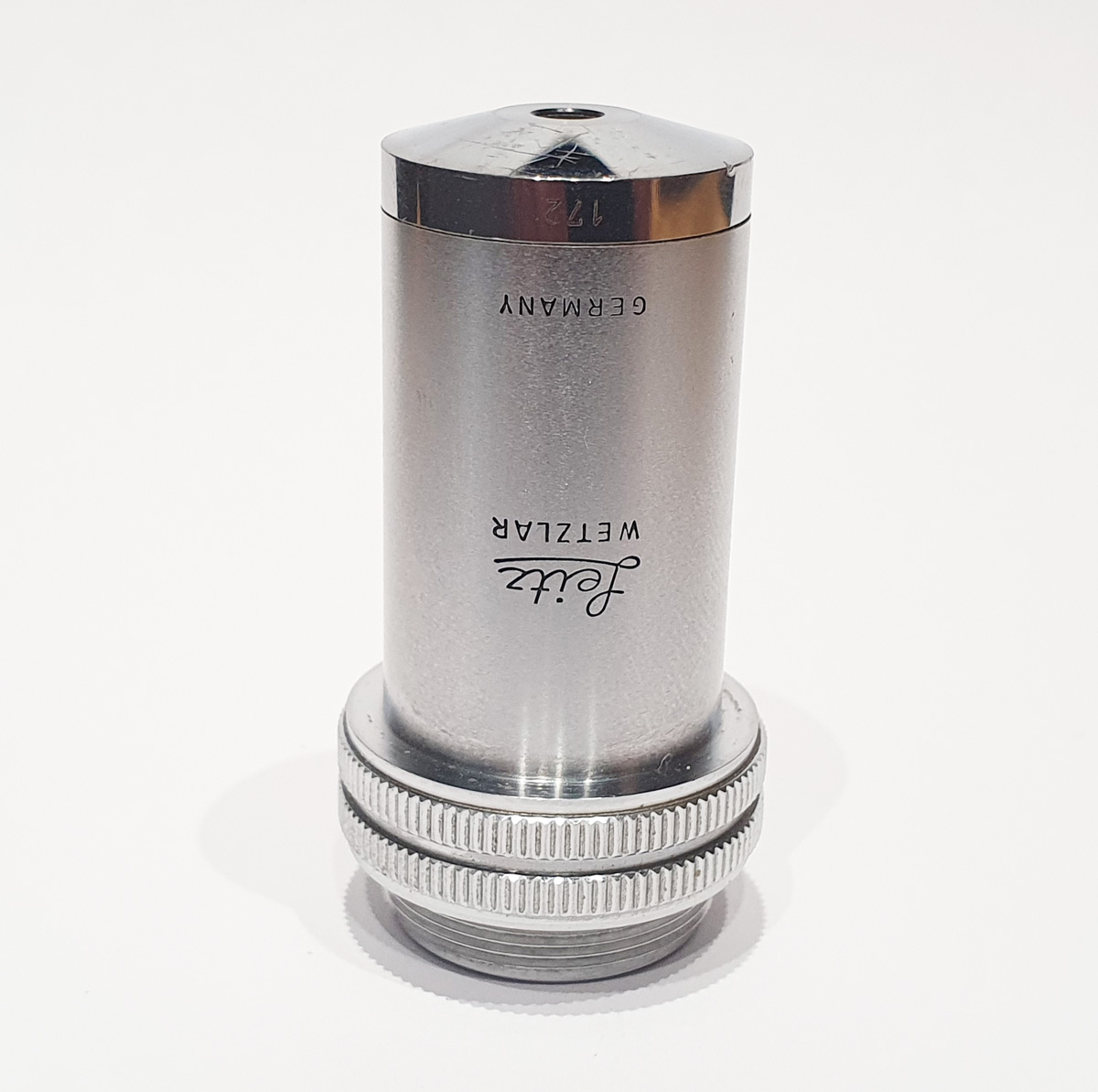
So, what is this odd objective? It’s a 170x Leitz Q NA 0.5 reflecting objective designed for use with 0.18mm thick coverslips and a 400mm tube length microscope. It’s rare and unusual, and there’s a little bit about it here in one of my previous posts. I’ll show a picture of it at the end of the post, but in summary this was designed for use between 220nm and 700nm and with its own specific reflecting condenser. It wasn’t designed to be used on a 160mm tube length microscope, or with an Olympus Aplanat Achromat condenser. Hence it was done just to see what type of image it would give. Imaging was done with 405nm light and using my monochrome converted Nikon d800.
What do the images from it look like? I first tried closing the condenser right down, and was a bit surprised to see it looked like a ‘dark field’ type of image, with a black background and the diatom showing bright white.
Image from the 170x Leitz NA 0.5 reflecting objective with the condenser iris closed right down
There was a surprising amount of detail here, given that this is being used way outside of the way in which it should be. Why does it look like a dark field image? My guess here is that when the condenser iris is closed right down the spot illuminating the sample becomes very small. There is a mirror in the middle of the objective (it is a reflecting design) and I guess this blocks the small spot of direct light so the only light that can pass through the objective is the indirect light scattered within the sample. However that is a hypothesis, and if anyone has any other ideas, feel free to drop me an email.
I also captured a video of the sample in this setup, where I changed the focus from above the sample to below.
When the iris on the condenser was opened up a bit the image returned to a typical bright field appearance, but with quite low contrast.
Image from the 170x Leitz NA 0.5 reflecting objective with the condenser iris opened up a bit
I wouldn’t want to use this objective like this, as there are plenty of ways to get better images, but with the iris closed down, the ‘dark field’ image looks quite cool, so I may try it for other samples in the future.
The 170x Leitz objective itself is shown below.
170x Leitz Q NA 0.5 reflecting objective, front side170x Leitz Q NA 0.5 reflecting objective, back side
You may well have noticed something odd here. This objective is 170x, but the field of view of the images looks not too dissimilar to those from the 60x objective in my previous post on this slide. Don’t forget that this objective was designed for use with a 400mm tube length microscope, but this one is 160mm. Effectively this reduces the magnification by 2.5x times (400/160), making the magnification just 68x. This is why the images look to be similar magnification to the ones with the 60x objective. This objective does have a big brother – a 300x one – and I may try that as well in the future given the results with this one.
Part of science is doing experiments just to see what will happen, even when you think it may not work. If we knew everything that was going to happen, why do research? With this, I tried imaging using an objective which common sense said wouldn’t work, but I think it’d be interesting to try. It produced an interesting result and I learned something new. Winner. As always, thanks for reading, and if you’d like to know more about this or any other aspect of my work, I can be reached here.
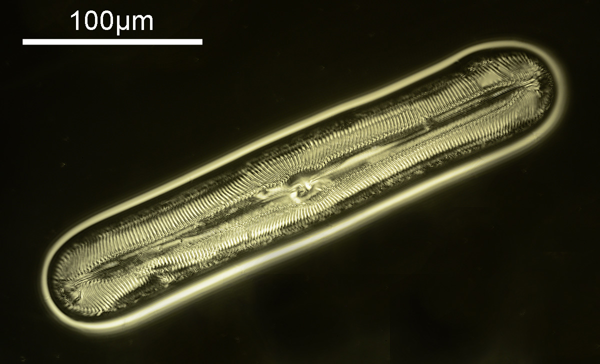
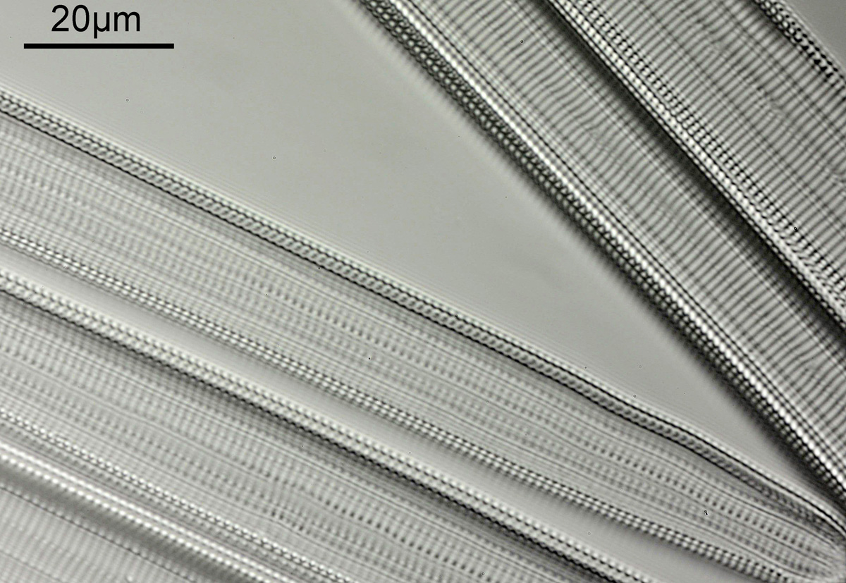
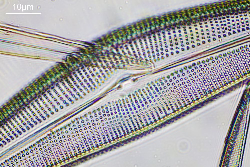
Using shorter wavelength UV light for microscopy can (and does) improve resolution, allowing smaller features to be resolved than with longer wavelength light. There are however times when using UV is impractical, or impossible, and in those circumstances, other approaches to improve the image are required. Today I’ll cover some basics about one of those approaches – the use of oblique lighting to illuminate the subject. With oblique lighting, we get to emphasize certain features on a subject, and this approach was used to capture the image shown below using my custom modified Olympus BHB microscope.
Synedra superba diatom structure, captured using 405nm oblique illumination
So what is oblique illumination? Basically, it is offsetting the direction of the incoming light to the subject compared with normal bright field microscopy. Changing the angle of light emphasizes some features within a subject, and the direction of the incoming light can be altered to highlight specific features depending on their orientation. As an example let’s take a look at three images of a Synedra superba diatom, captured using an Olympus 40x Dplan Apo UV objective, using 405nm light, on my Olympus BHB. Firstly, normal bright field, with the light coming from directly below.
Image using normal bright field illumination
And now, two images using oblique illumination, one at 90 degrees to the other.
Image using oblique illumination in one orientationImage using oblique illumination with the light at 90 degrees to the first one
As can be seen from the images, using oblique illumination highlights certain features, and by changing the direction the light comes in from different features can be emphasized.
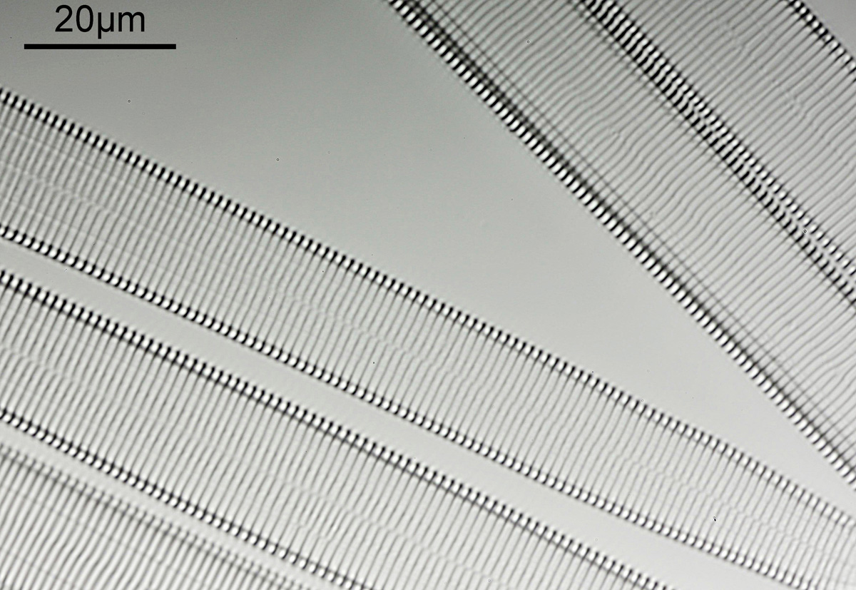
The images above have been cropped from the original and have not been cleaned up (they still show all the imperfections from the camera sensor – microscopy will show everything on the sensor, even when you think you have cleaned it). Below is a cleaned up image of the Synedra superba diatom slide using 405nm oblique illumination with the Olympus 40x Dplan Apo UV objective.
Synedra superba diatom slide using 405nm oblique illumination with the Olympus 40x Dplan Apo UV objective
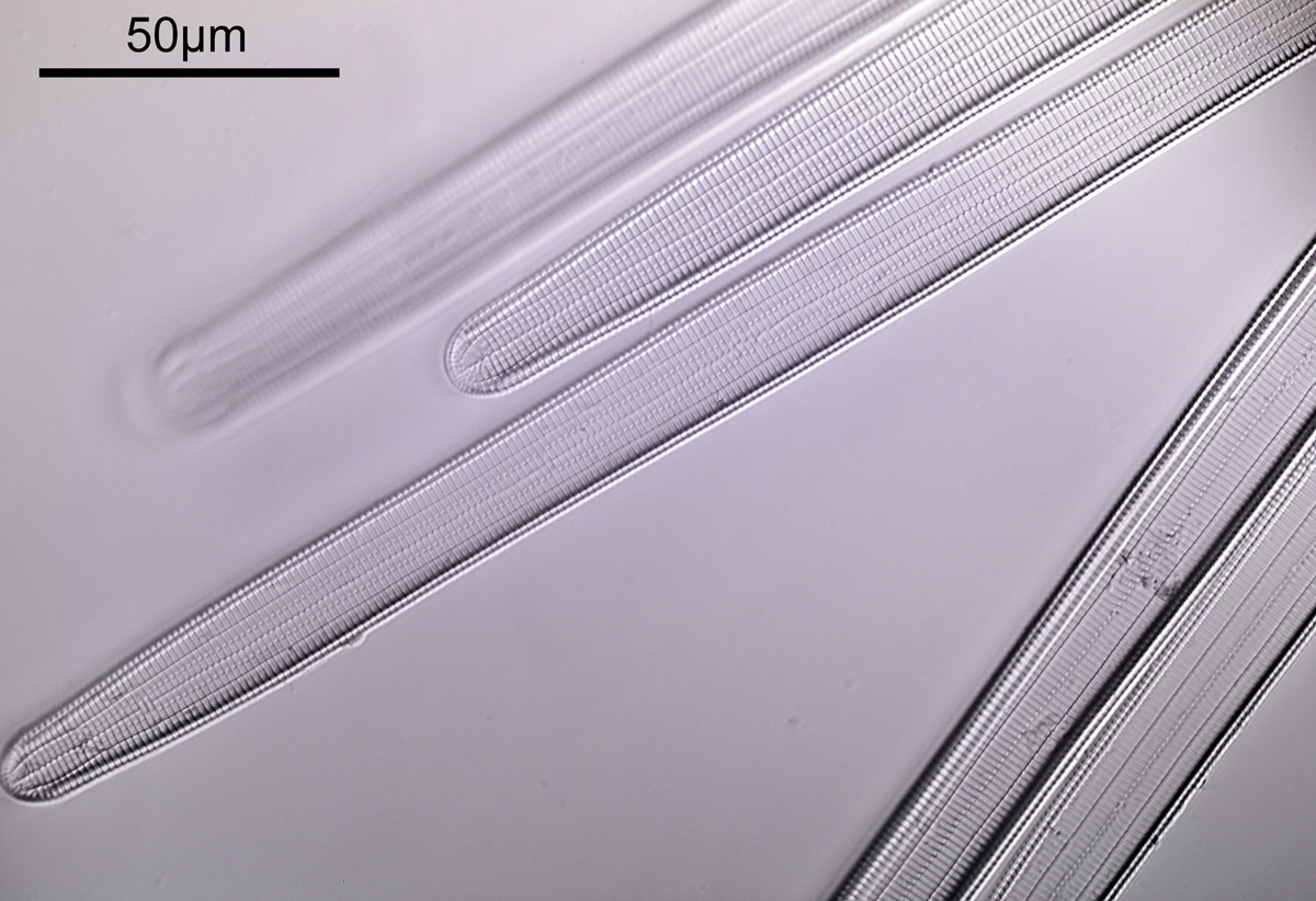
The oblique illumination gives an almost 3D appearance to the image which I really like, and there is certainly plenty of resolution given the NA of the objective (NA 0.85). Note, I have flipped this horizontally, as I like the composition better this way round. However I still wanted to go further, so I broke out the 60x Olympus SPlan Apo (NA 1.4) oil immersion objective. The objective and condenser were oiled to the slide and this is what an image from that looks like using 405nm oblique illumination.
Synedra superba diatom slide using 405nm oblique illumination with the Olympus 60x SPlan Apo objective
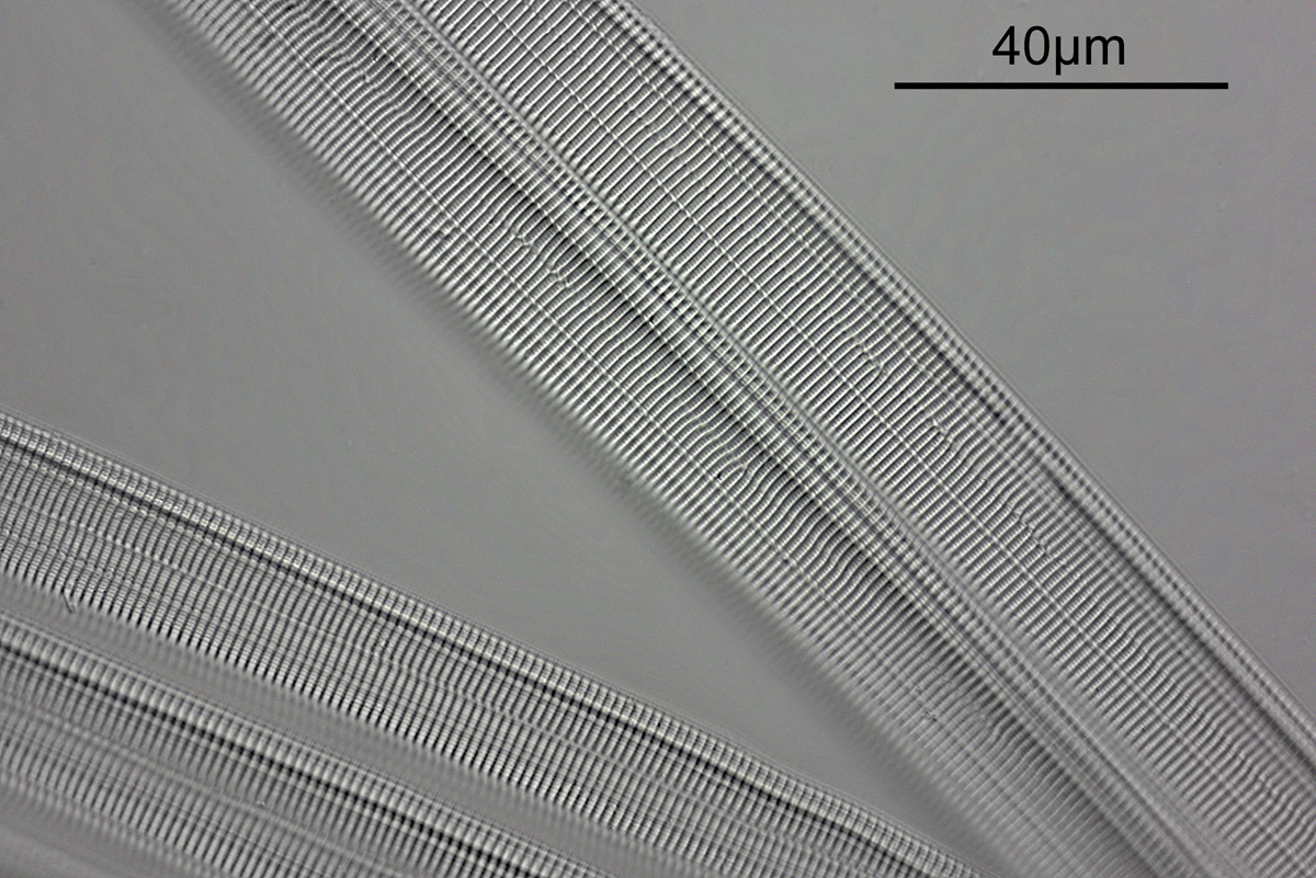
There is a big step up in resolution with this objective, as expected given its much higher NA. However showing the images at this size online doesn’t really show that, as they have to be reduced in resolution for the website. Below is a crop from the image above, which has also had to be shrunk in resolution).
Synedra superba diatom slide using 405nm oblique illumination with the Olympus 60x Splan Apo objective
It is interesting to note in this image the ‘imperfections’ in the ‘perfect’ structure. However as mentioned, even this was reduced in resolution for sharing. Below we go in even tighter, and keeping the original image resolution.
Synedra superba diatom slide using 405nm oblique illumination with the Olympus 60x Splan Apo objective, original resolution
This tight crop shows some really impressive detail, with the small features being about 200nm across.
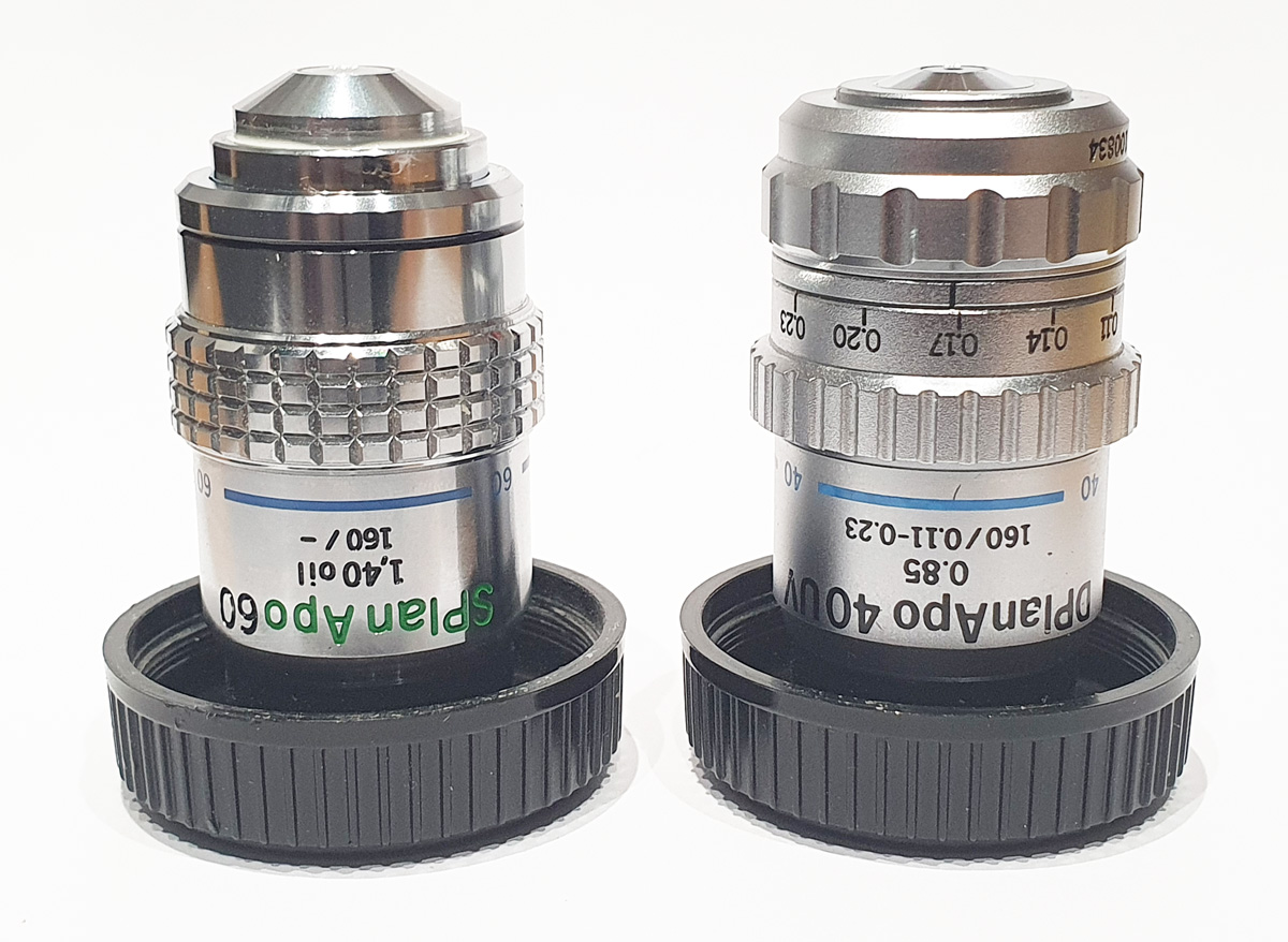
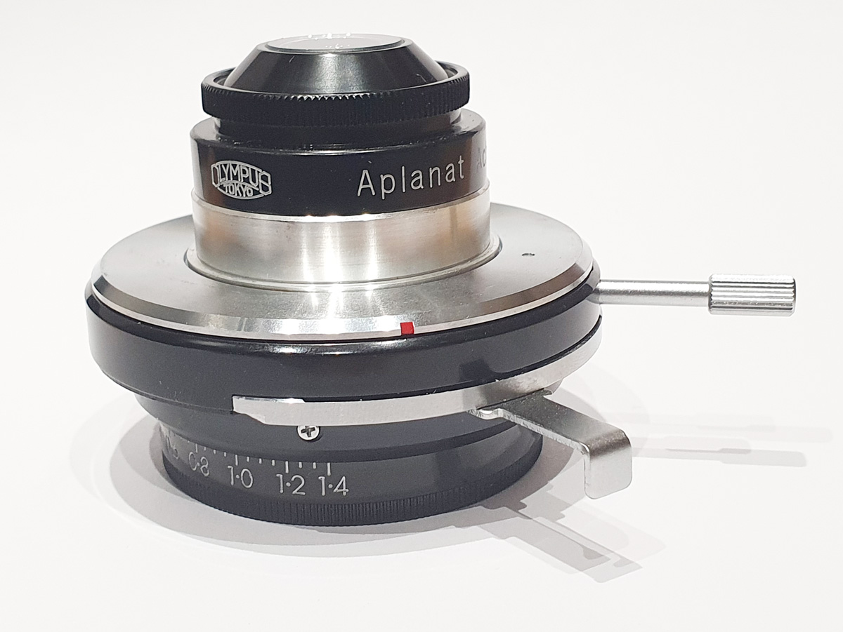
I’m a bit of an imaging geek, so at this stage I’ll show the objectives and condenser that were used for this work, and the slide itself (which cost me about £30 on eBay).
Olympus 60x SPlan Apo (left) and 40x DPlan Apo UV (right) objectivesOlympus Aplanat condenser in normal position (not setup for oblique illumination)Olympus Aplanat condenser setup for oblique illuminationSynedra superba slide by Arthur Cottam
The slide was made by Arthur Cottam and is over 100 years old (more information can be found out about him here).
I’d also like to give a bit of a ‘shout out’ to a company – J.B Microscopes Ltd. When I bought the 40x Dplan Apo UV objective on eBay, the coverslip thickness correction collar was stuck and wouldn’t move (as far as I know the objective was bought new and then kept in a cupboard for 40 years, so presumably the grease had set). J.B Microscopes were able to fix this for a very good price and send it back to me within a few days of sending it to them, so I would definitely consider using them again in the future.
I hope that has been interesting for you to see. Microscopy continues to amaze me, as do the details I am able to see with my little custom made Olympus BHB UV microscope. Thanks for reading, and if you’d like to know more about this or any other aspect of my work, you can reach me here.
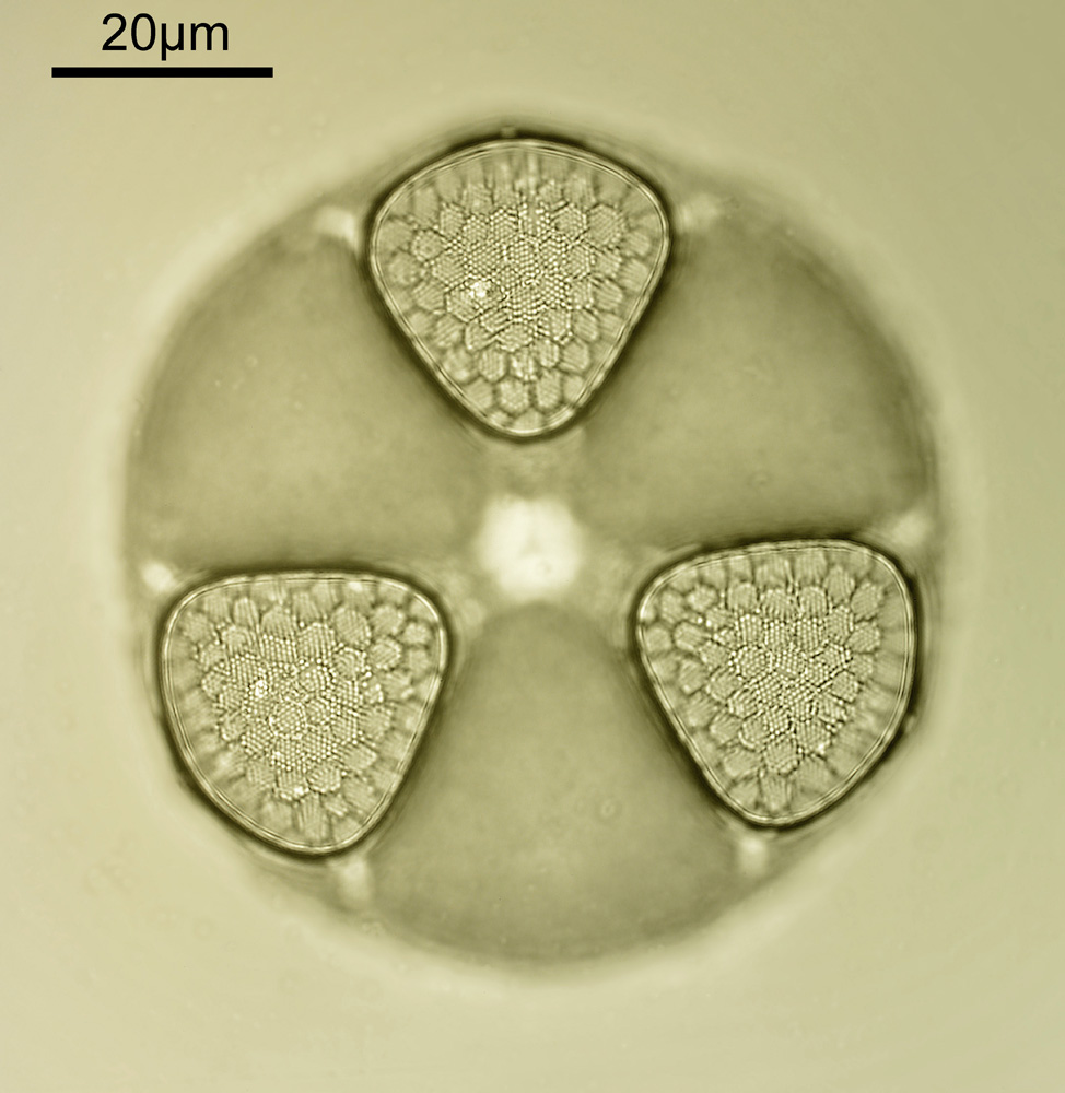
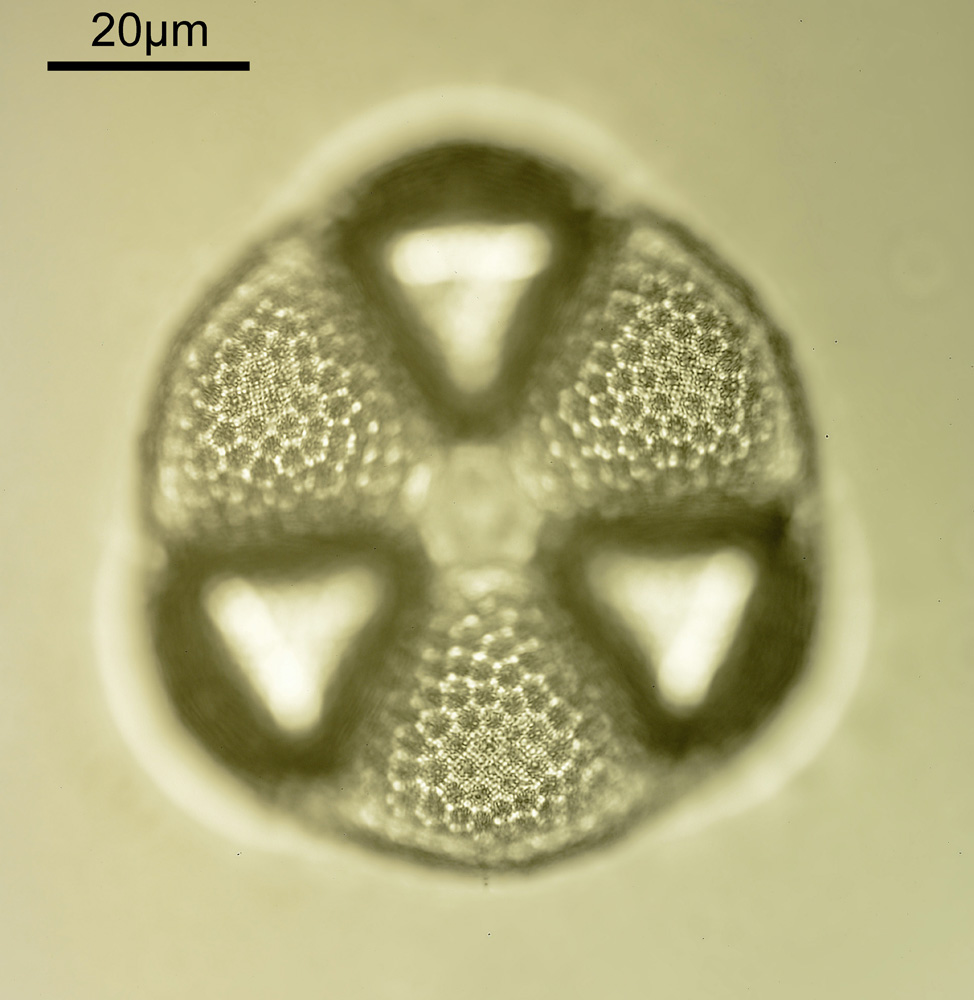
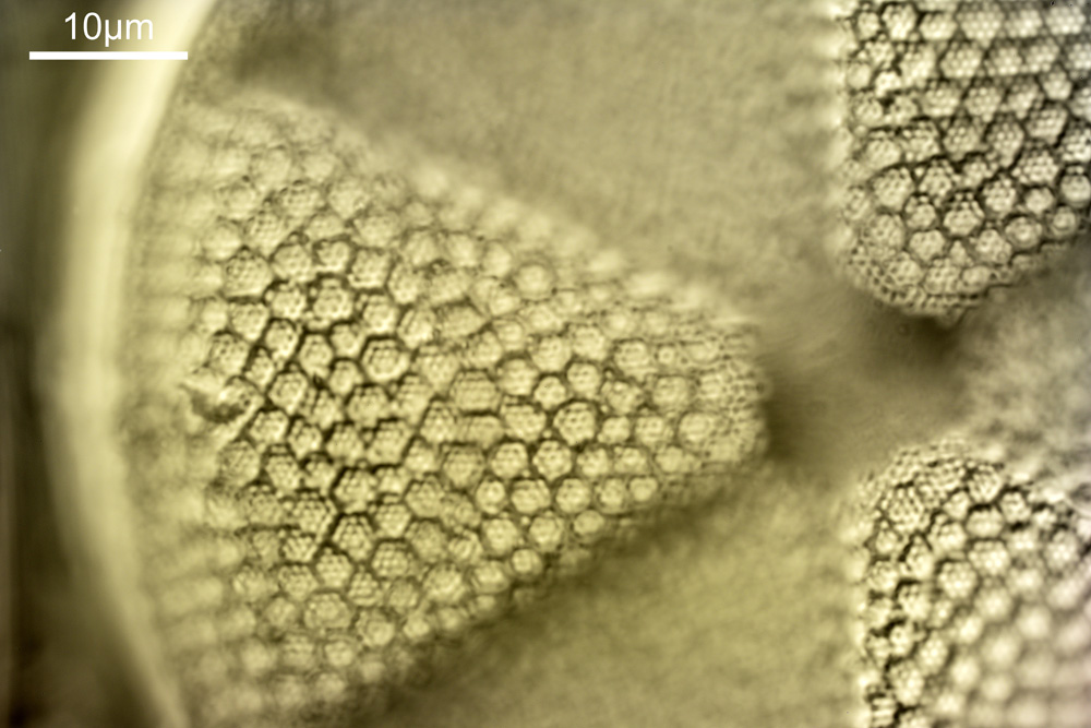
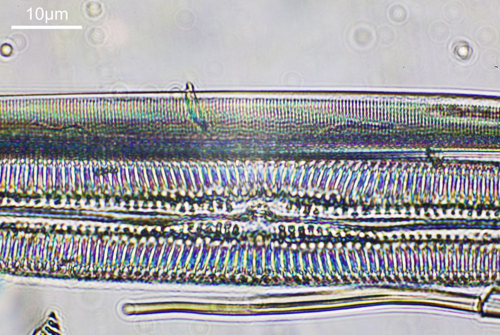
Very often I get caught up in showing my microscope images, and while they are nice to see the magnifications can sometimes be so extreme it is difficult to get a feel for what it is you are actually looking at – for example see below, which shows part of a diatom taken using 313nm light on my UV microscope.
Closeup of a diatom structure using 313nm bright field microscopy
I’m not too good on naming diatoms yest, but I think the one above is an Actinophycus senarius. Today I want to go on a bit of journey with you, from large scale down to the very small. We will go from ‘centimeter’ down to ‘nanometer’ and take a look at the images at those different scales. Note, the images being shared here are low resolution ones of the originals, and and as a result are less sharp than the originals, but ideal for sharing online.
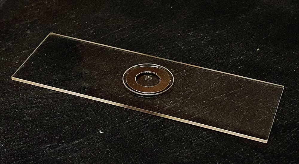
We start on the large scale with the microscope slide itself. This is standard sized one of 7.5cm by 2.5cm and the image was just taken with my camera phone.
The slide with the diatoms on it
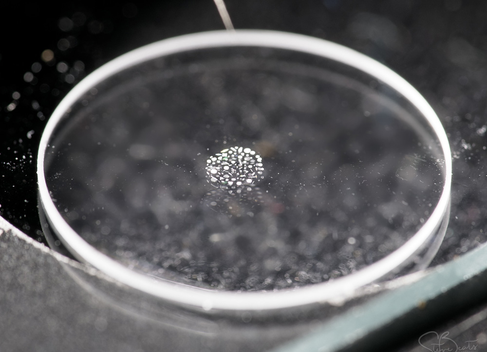
This slide and coverslip is quartz rather than glass to allow me to use short wavelength UV light to look at the sample – glass would be essentially opaque down at 313nm. The diatoms are in the middle of the slide surrounded by a metal washer and with a coverslip on top, and in the image above you can just about see it. It becomes easier to see if we zoom in a bit – the image below was from the gentleman who very kindly made the slide for me and you can make out the individual diatoms in the arrangement. This cluster of diatoms is about 2mm across.
Diatoms arranged on the slide
Next, I thought it would be good to get an overview of the diatom arrangement using the microscope. I should say at this point that all the microscope images which are shown below were taken using a monochrome converted Nikon d800 (conversion done by MaxMax in the US). This has very good UV sensitivity and tends to be my ‘go to’ camera for the microscope.
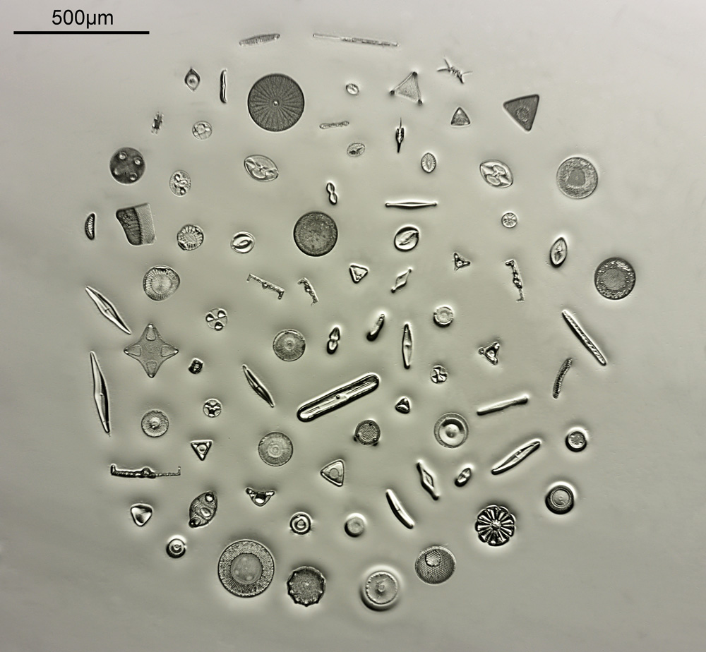
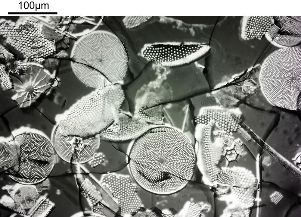
The image below was taken using white light bright field imaging using a 4x Zeiss Planapo objective, and with oblique lighting.
4x Planapo image of the diatom arrangement using white light oblique lighting
With the image above you can see the individual diatoms, but it is difficult to make out structures. As you can see the whole arrangement is about 2mm across. The objective has a relatively good Numerical Aperture (NA) for the magnification – the NA is 0.16 – but it is not going to be enough to show fine structure. Using oblique lighting (I used an Olympus Aplanat condenser which has this ability built in to it) gives an almost 3D appearance to the image.
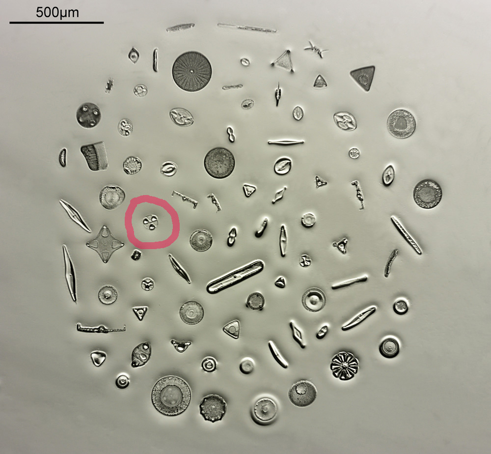
The next stage is to highlight a specific diatom and look closer with a higher magnification. The one I’ll be looking is highlighted in red in the image below.
The diatom to be looked at in more detail (highlighted in the red circle)
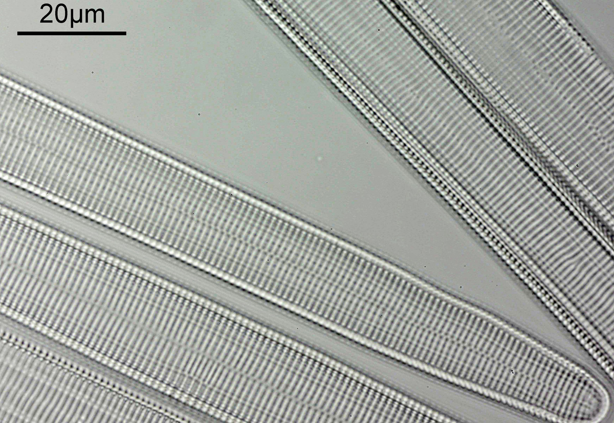
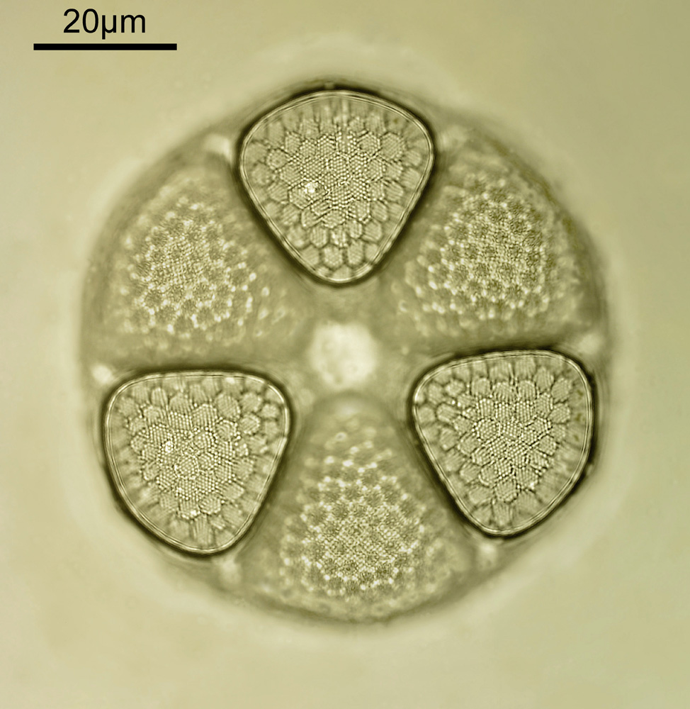
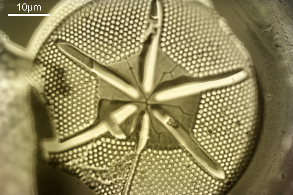
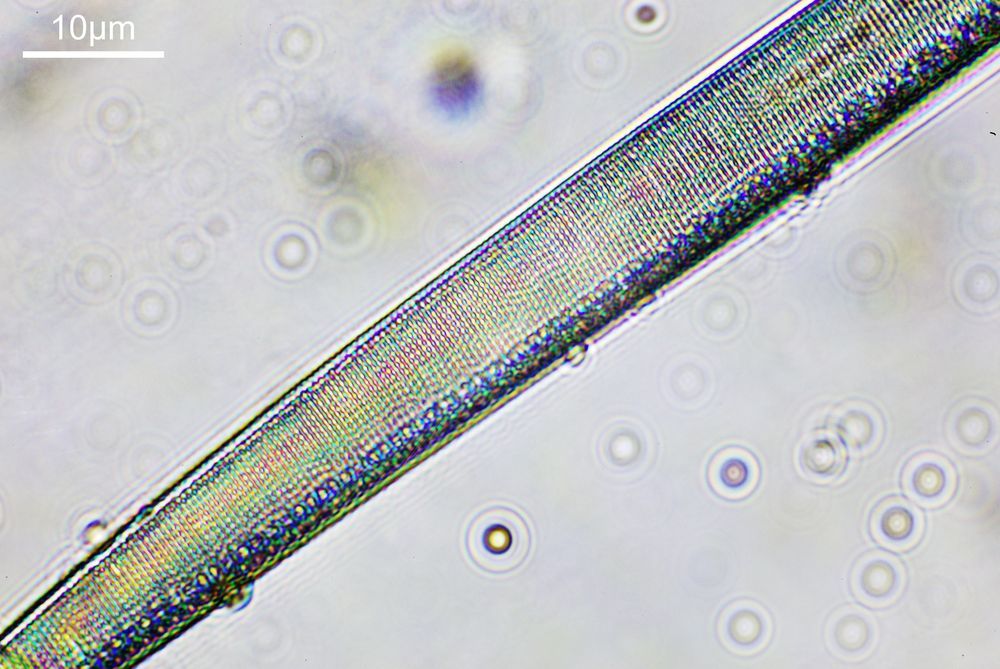
To look closer it’s time to go to a higher magnification (a 40x objective) and use 313nm light – the shorter wavelength gives better resolution for a given numerical aperture. The objective of choice was a Leitz 40x UV objective with an NA of 0.65. I used a Zeiss quartz condenser with an NA of 0.85, and the image was straight bright field. First I’ll show two images of the diatom in question.
Diatom at 313nm, using a Leitz 40x UV objective, focused on the top of the structureDiatom at 313nm, using a Leitz 40x UV objective, focused on the bottom of the structure
As can be seen, even at this magnification, the depth of field is very shallow, and the height of the sample needs to be changed to get the high and low parts of the top surface of the diatom in focus. When the top of the sample is in focus, it is very sharp – this part of the diatom is what is fixed to the coverslip using gelatin. It is possible to combine the two images above using stacking software (I use Zerene Stacker), to produce the following.
Stacked image of the diatom
With this magnification, it is possible to make out some small features on the diatom, and it shows it in its entirety, so it is a good intermediate magnification to use. But I can go to even higher magnifications and with an objective with a larger NA to get even more detail.
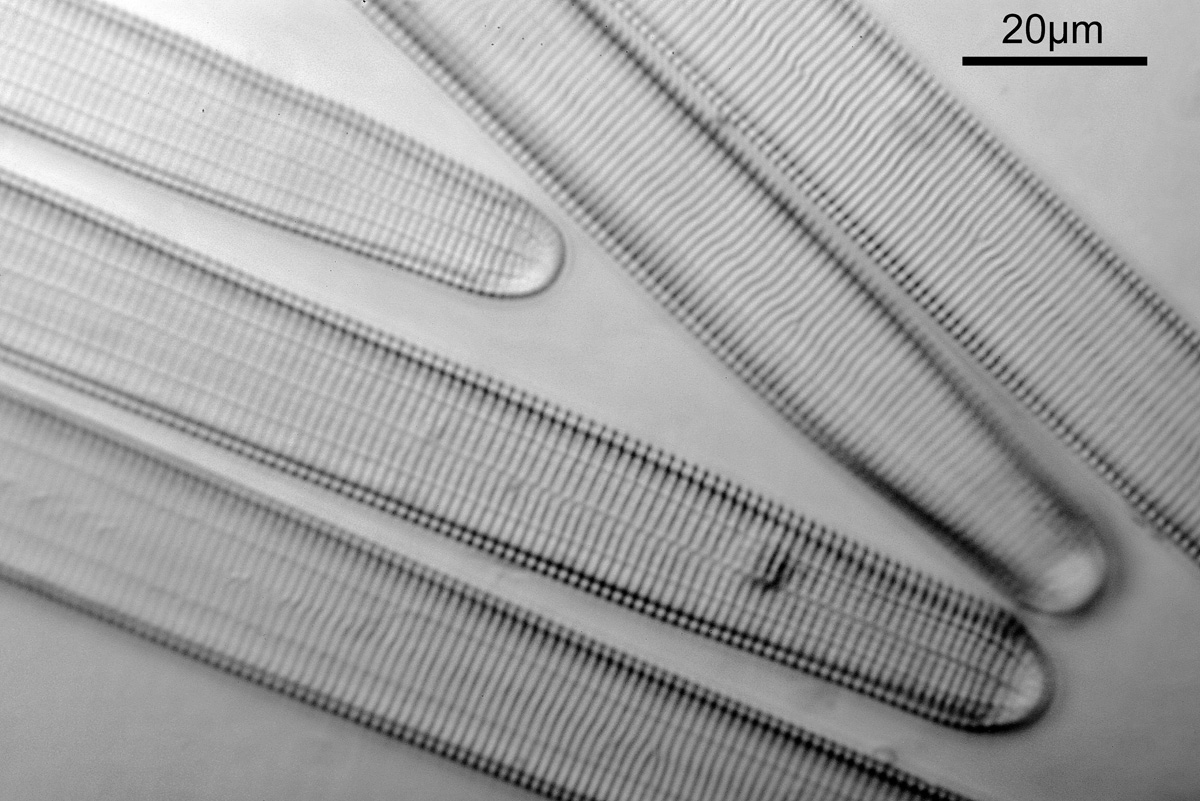
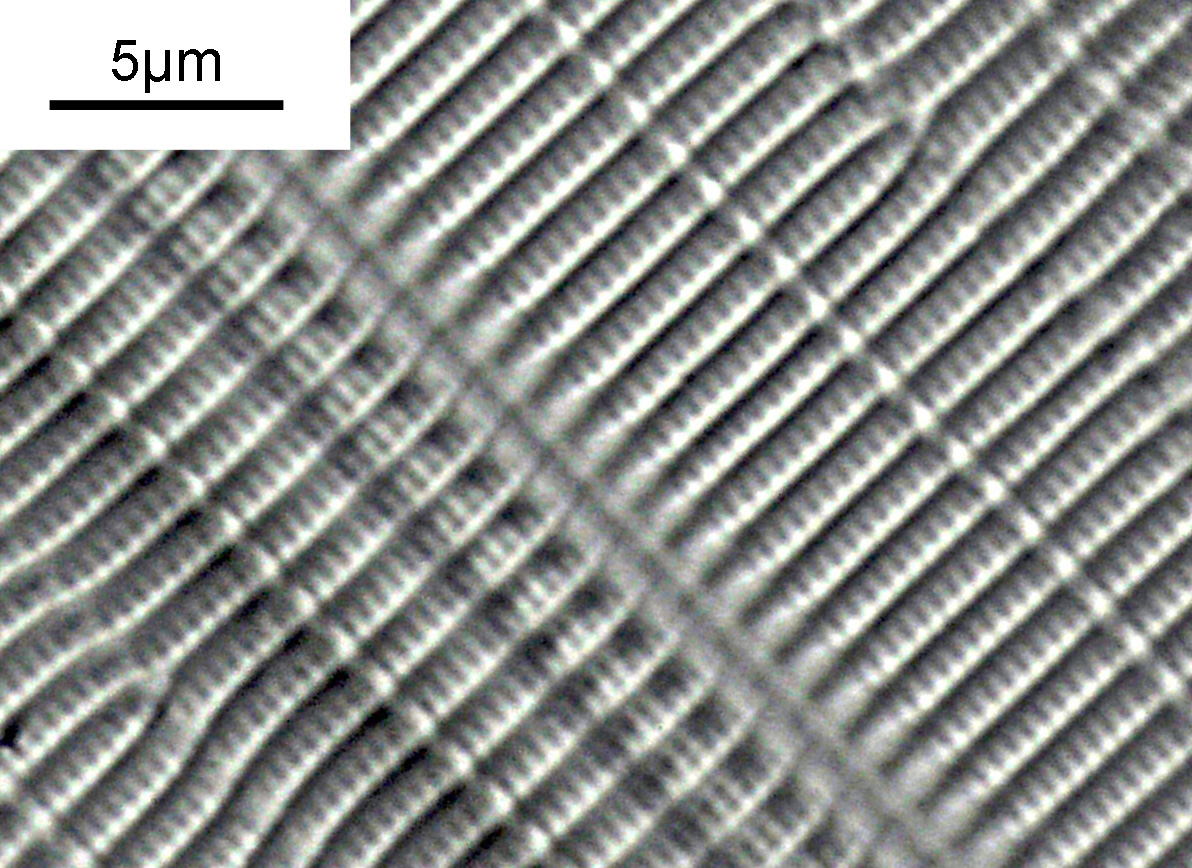
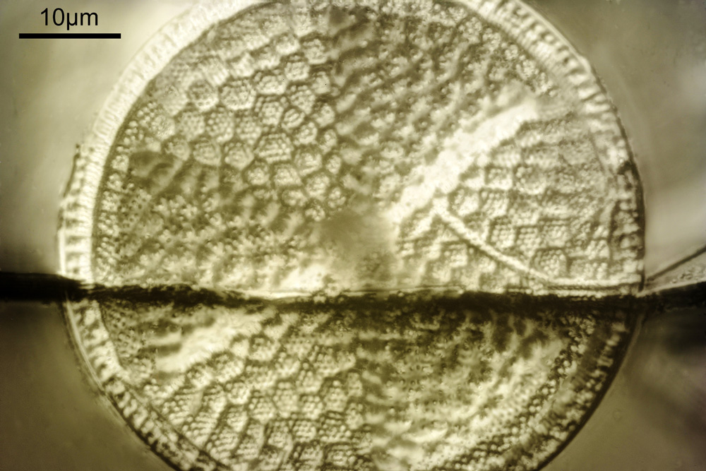
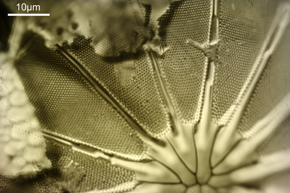
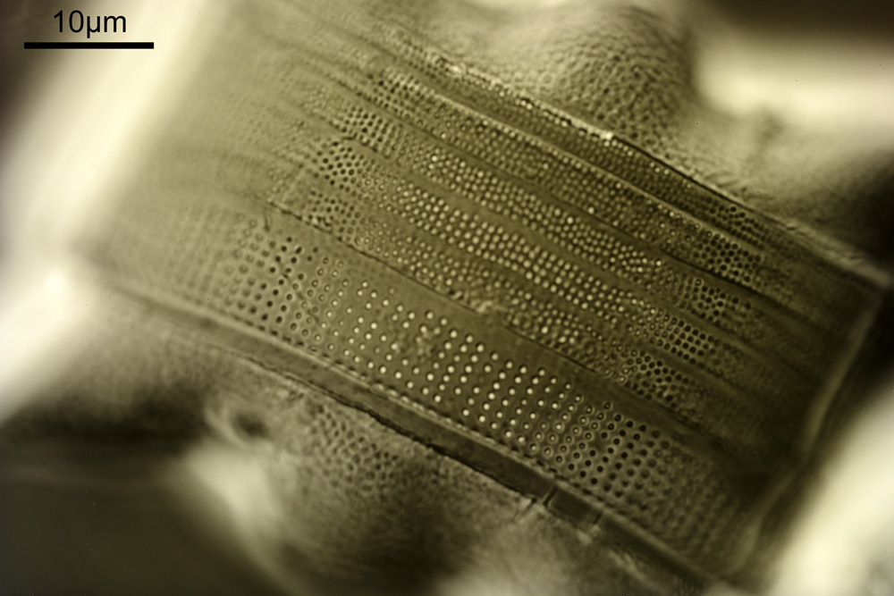
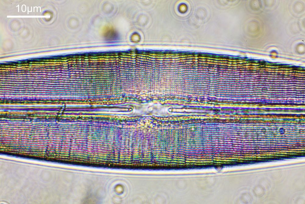
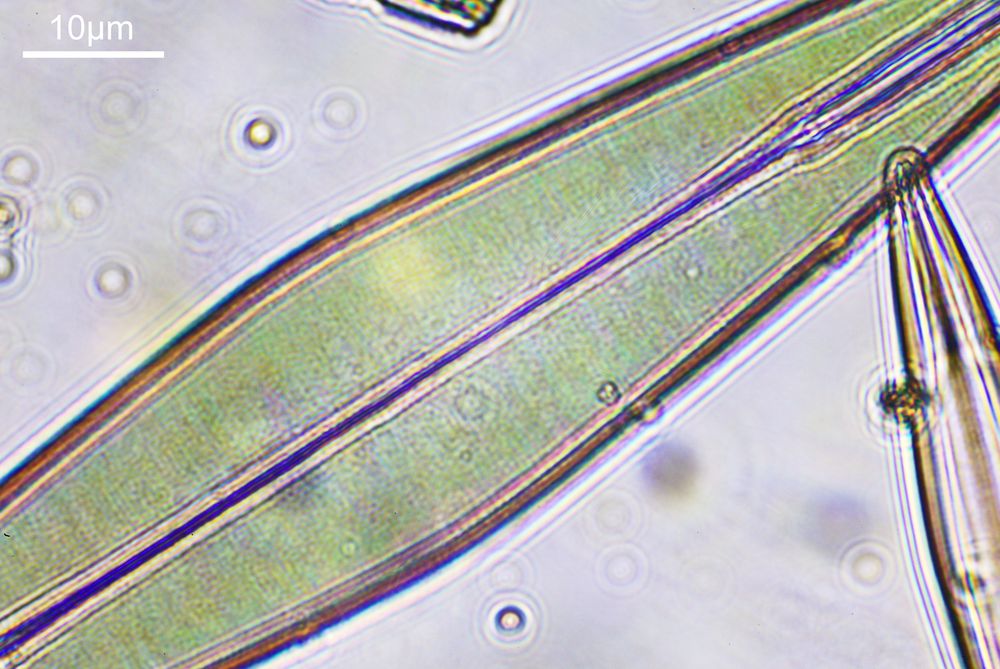
Next, we have an image showing part of the diatom using a Leitz 100x UV objective and Zeiss quartz condenser with an NA of 1.25, again at 313nm. The image is now shown as monochrome rather than sepia toned and has been rotated 90 degrees. This is the same image as at the top of this article.
Leitz 100x UV objective image of the diatom at 313nm
At this magnification and with such a high NA, the depth of field is now tiny, and the best focus is on the parts of the diatom with the gelatin which are attached to the coverslip. The observant amongst you will have noticed that there is any array of dots on the parts of the diatom which are in focus. In the 100x image, these look black, and in the 40x image they look white. I’ve noticed this with diatom images, as you slightly change the focus, what looks to be dark dots go white, and then dark again. I believe this is to do with the size of the dots and diffraction of the light as it comes through the holes – as the light comes through it diffracts and then as you change focus you get constructive and destructive interference, and the features change from light to dark. For the 40x image, it happened to be where thy looked light, and or the 100x image, it was sharpest where they were dark. As they are holes, it makes sense to me for them to look dark.
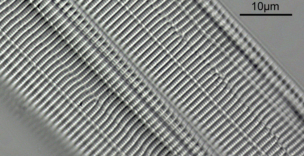
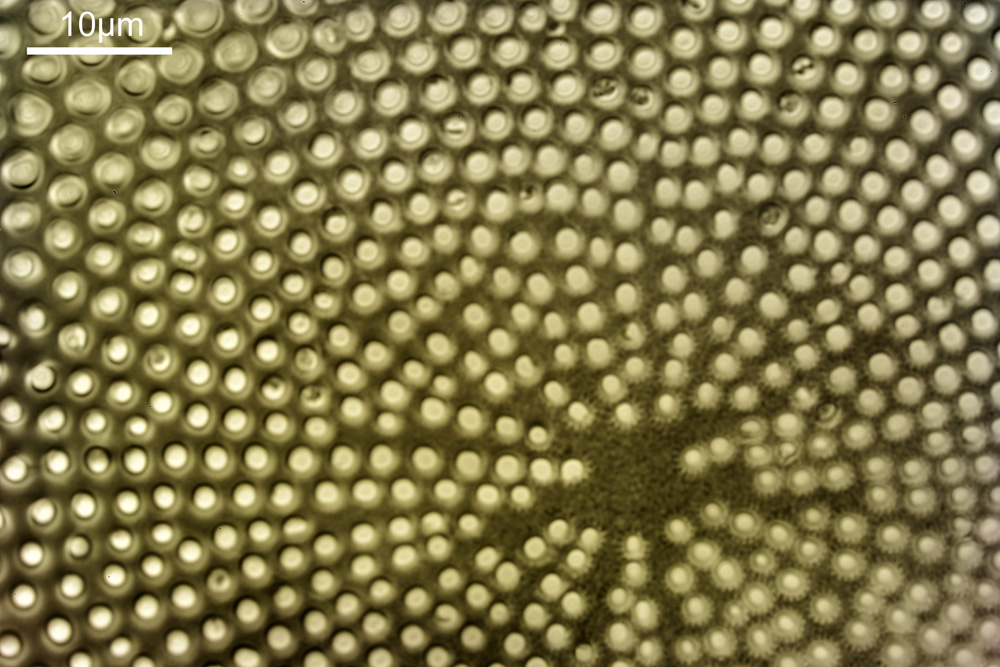
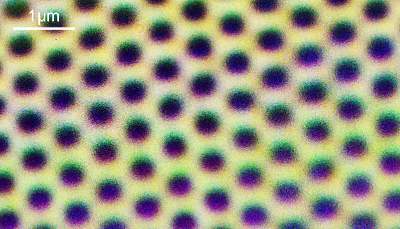
For a final image the one above can be cropped, focusing in on the top right had part. This is shown below.
Cropped part of the image using the Leitz 100x objective, taken using 313nm light
In the cropped image the holes themselves become quite clearly resolved. Those ‘holes’ are about 300nm across. Normally to get images with this type of resolution, it’d be easier to use scanning electron microscopy, and while it would be possible to resolve these features with optical microscopy without using 313nm UV light, it becomes complex, relying on either more involved lighting setups, or more processing, or even different ways of preparing the sample. With UV, because of the short wavelength involved the resolution for a given NA increases (as per Abbe’s equation), and in fact this was originally why UV microscopy was invented – the pursuit of resolution. While it is an old technique now (and I have even had some microscopists describe as a ‘dead technique’ than no-one would use these days) it still has its uses in the 21st century. As a technique it is actually relative simple to do (once you have the equipment), and means that simple bright field imaging can be used making image capture and processing less complex.
I’ll be giving a talk on the design and building of my UV microscope at the Royal Photographic Society Imaging Science Group Good Picture Symposium 2022 in London in December (for details see here) where I will go into the challenges with the technique and share more high resolution images taken with it, including some of my work on the imaging of sunscreens, which is what got me started on this journey.
It’s been fun going from something that is large enough to be seen by the naked eye, all the way down to the nanometer level, and I hope you have enjoyed it as well. As always, thanks for reading, and if you’d like to know more about this or any other aspects of my work, I can be reached here.
I’m very happy to be giving a talk to the Royal Photographic Society Imaging Science Group later this year (3rd December 2022, at the University of Westminster in London) as part of their Good Picture Symposium. The day will consist of 7 talks from imaging experts in different fields and the flyer for the event is shown below.
Please contact Dr Mike Christianson for tickets using the details shown in the flyer above, and you don’t need to be an RPS member to attend – these talks are open to all.
If you are a regular visitor to my site you will know that I recently got a rather odd microscope slide made by Horace Dall. The side was of diatoms which had been ‘mounted’ in TiO2, with the aid of improving contrast (you can read about that here and here). While looking around for more information on this process, I was nudged in the direction of a slide maker called John Dale, which had used aluminium coating, again with the idea of improving contrast. As it turned out the Postal Microscopical Society in the UK had some slides of his which had been prepared in this manner, so I joined them to be able to have to opportunity to have a look at them. The slides turned up this week, and I thought I would share a few of the initial images.
As an initial image, I did a fairly low magnification photo in visible light (546nm). This is a standard brightfield image with the light below the sample.
Low power brightfield image of a John Dale Aluminium coated diatom slide
The diatoms can clearly be seen, but unlike a normal brightfield image the areas between them look dark here due to the aluminium layer. Cracks in that layer can also been seen (the slide was made in the 1990s and these types of coatings can have quite a lot of residual stress present in them).
I was keen to have a look at this slide in the UV, but as it is glass that limited me to 365nm. I also wanted to go to higher magnification. So I decided to use a Nikon 100x UV-F objective, as this has great UV throughput at 365nm, and was designed to be used with standard glass coverslips of 0.17mm thickness. Below are shown some of the images from that objective (resolution has been significantly reduced for sharing online – these ones are 1000 pixels across, vs the originals which were over 7000).
John Dale Aluminium coated diatom slide at 365nm with a Nikon 100x UV-F objectiveJohn Dale Aluminium coated diatom slide at 365nm with a Nikon 100x UV-F objectiveJohn Dale Aluminium coated diatom slide at 365nm with a Nikon 100x UV-F objectiveJohn Dale Aluminium coated diatom slide at 365nm with a Nikon 100x UV-F objectiveJohn Dale Aluminium coated diatom slide at 365nm with a Nikon 100x UV-F objectiveJohn Dale Aluminium coated diatom slide at 365nm with a Nikon 100x UV-F objective
Apart from the first image in the above set (which was a stack) these are all single, unstacked photos. My monochrome camera produces a slight colour cast to 365nm images, which I normally remove, but I actually quite like it here so have left it on. In some of the images I seem to be seeing features down to about 3-400nm across which given that I was using a 0.85 NA condenser and didn’t use glycerine immersion fluid with that (although I did with the objective) is about what I’d expect to be getting with this setup at this wavelength.
In addition to the photos I also captured a video clip;
The video clips shows the sample being moved vertically, so the different structures within the diatom can be seen.
The John Dale slides have proved to be really interesting to look at, even with visible light and the coatings has improved the contrast. I’d like to day here, that the Postal Microscopical Society is well worth a look at if you’d interested in microscopy and want to be able to get some interesting slides to look at. Thanks for reading, and as always, if you’d like to know more about this or any other aspect of my work, you can reach me here.
P.S. apologies to my American colleagues – I have of course been spelling aluminum incorrectly in this article….
While imaging science is an area I actively research, I’m in the position of having access to some great and unusual photography gear and sometimes it is nice just to get out and enjoy it. I was recently approached by Simon of Simon’s Utak fame on Flickr (link to his profile here). Simon is a great photographer and a huge Takumar fan and was interested in coming to see and use one of the rarest Takumars – the 85mm f4.5 Ultra Achromatic Takumar. This diminutive little lens packs a real punch, and having no glass in it all (the elements are quartz and calcium fluoride) is capable of imaging from the deep UV, through the visible and well into the IR, and is something I have used for my UV imaging. I personally think it is great to share experiences with these almost mythical pieces of photographic history so I invited him over for a photo day and to swap stories.
This is one of his photos of the lens (Flickr post here) taken using another of my more unusual lenses he was keen to try out – a Zeiss Ultron 50mm f1.8;
Asahi 85mm Ultra achromatic takumar on Pentax K-1, Simon Utak, 2022.
Simon is starting to share his images now, which he took on his un-modified, visible light cameras, and you can see the first of them here.
Thanks for reading, and if you’d like to know more about this or other aspects of my work, I can be reached here.
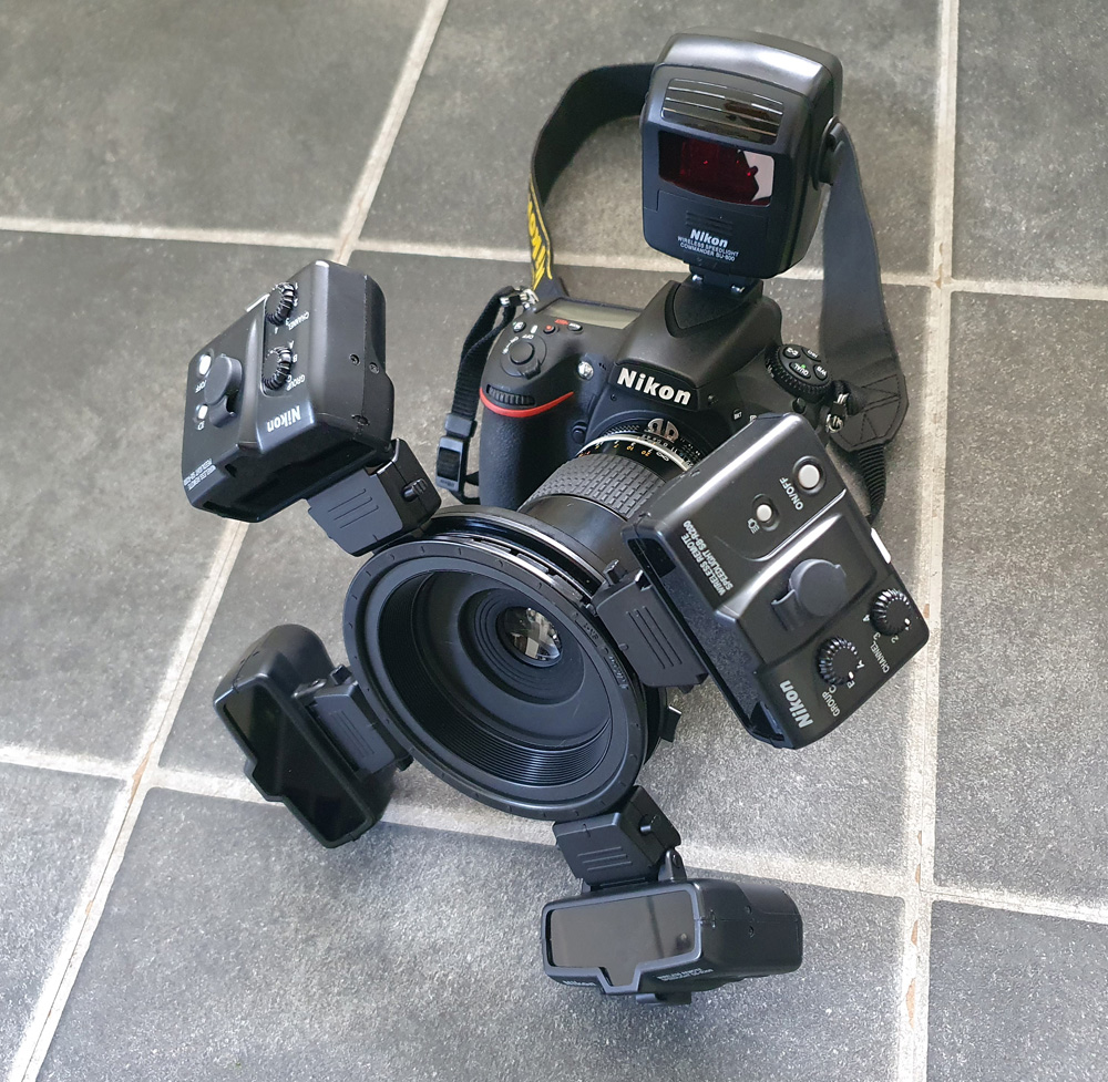
When I started UV imaging of sunscreens about 5 years ago, I ended up having to get various bits of kit to try, not knowing what would work and what wouldn’t. This is normal when building new imaging methods, as it is difficult to predict what will work and what wont. One lighting setup I got at the time was a UV modified Nikon R1C1 flash system. Advanced Camera Services Ltd here in the UK (where I bought the UV modified camera from) replaced the flash windows with UV transparent material which also blocked the visible light. At the time, I assumed that I needed the flashes to be visible blocking rather than just leave them as emitting everything for UV imaging which turned out not to be correct. However, the other lighting I got worked for the project, and this modified R1C1 has sat in a box ever since. Until a few days ago.
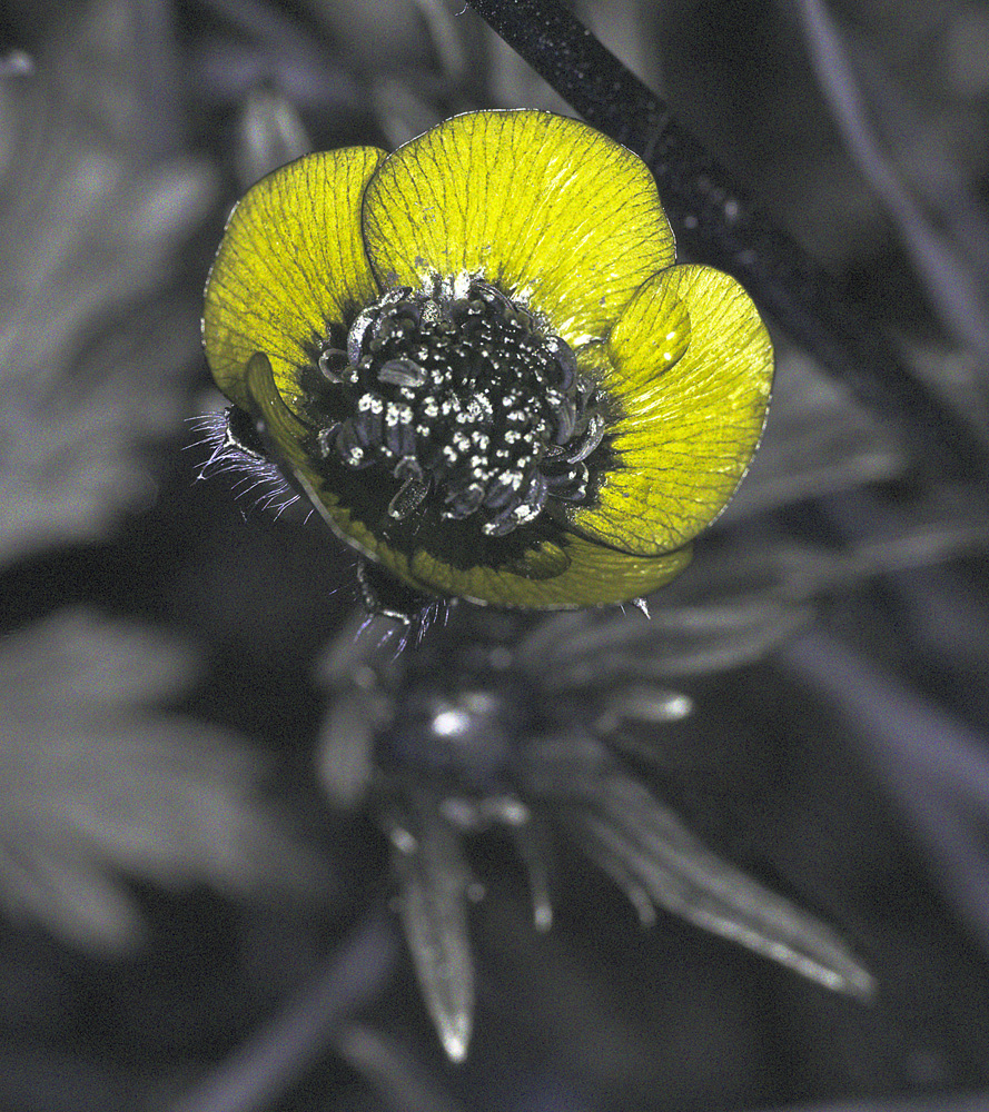
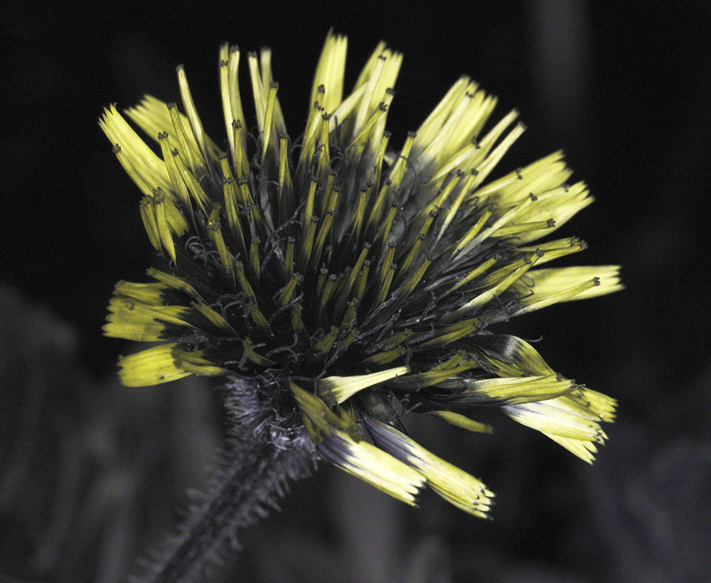
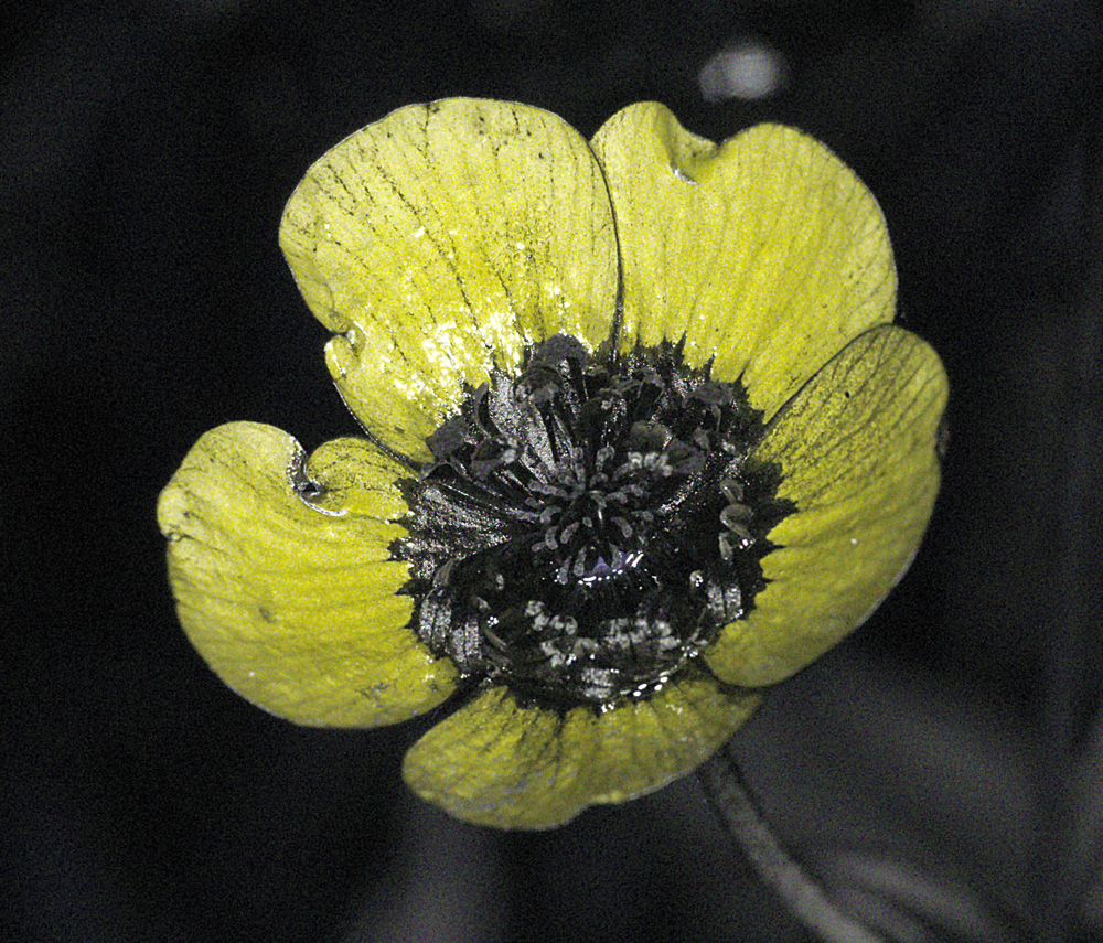
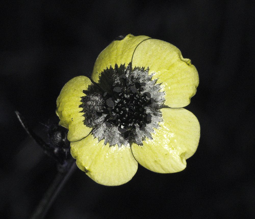
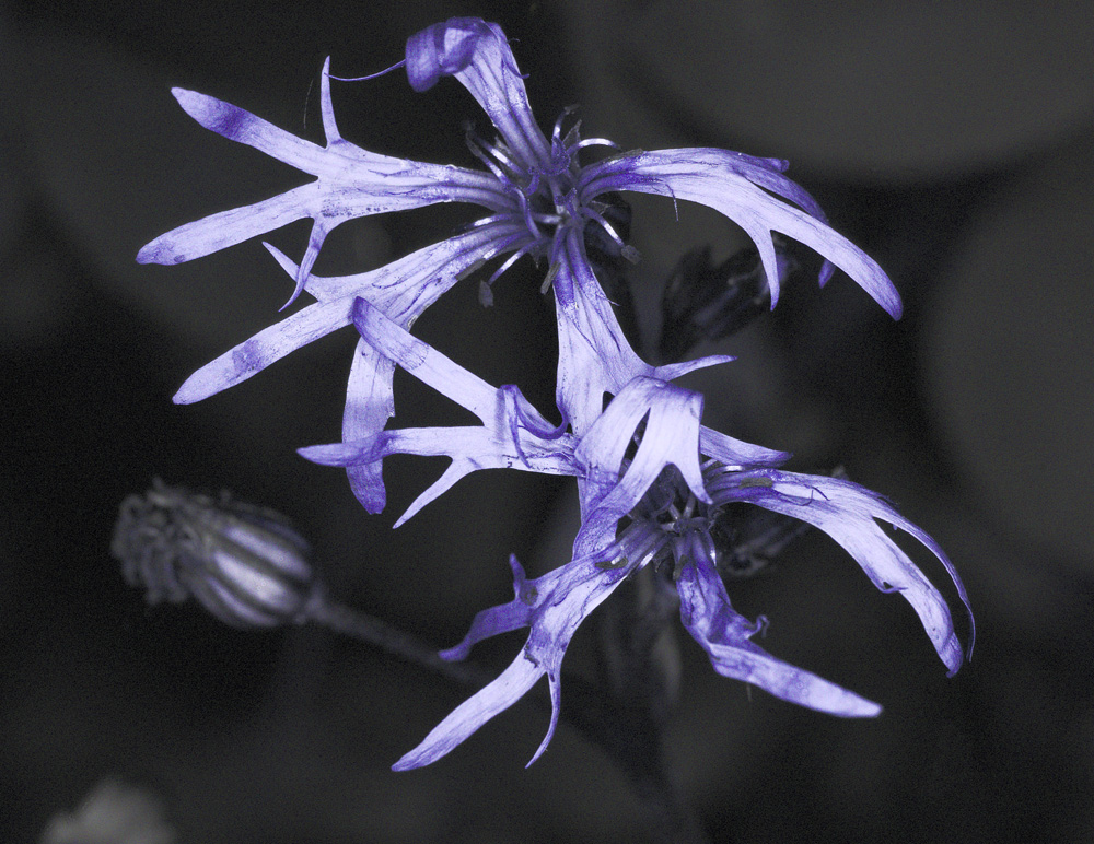
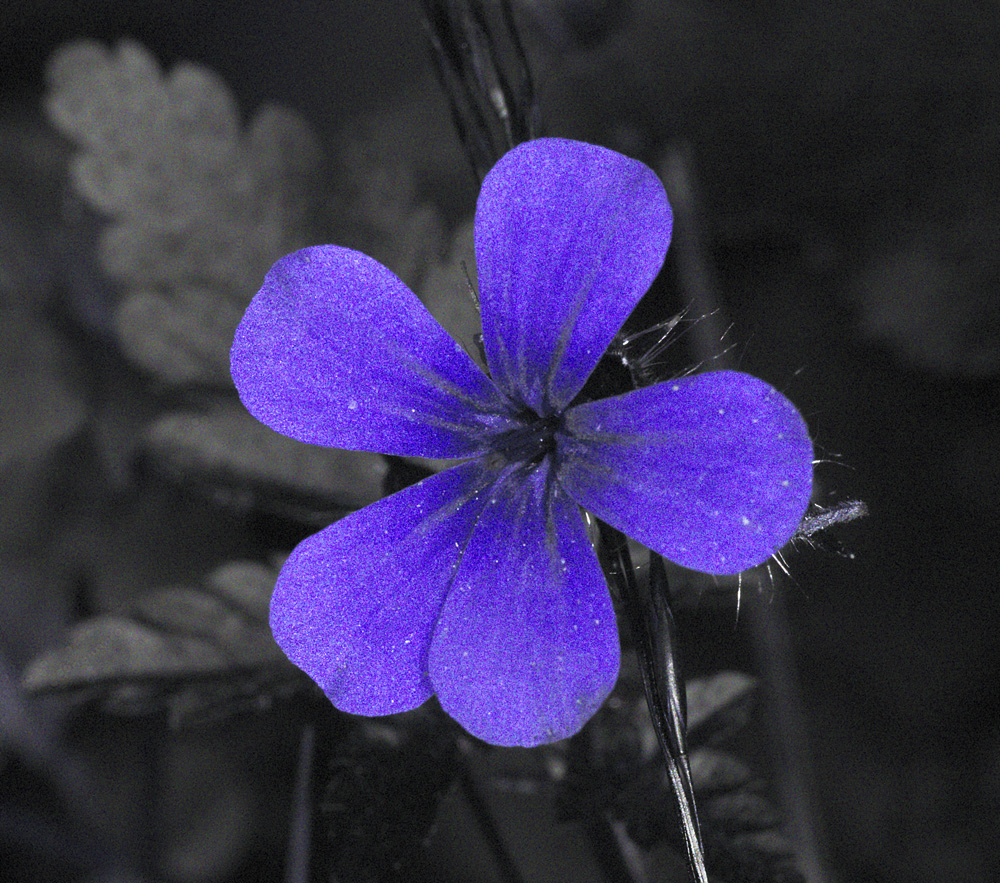
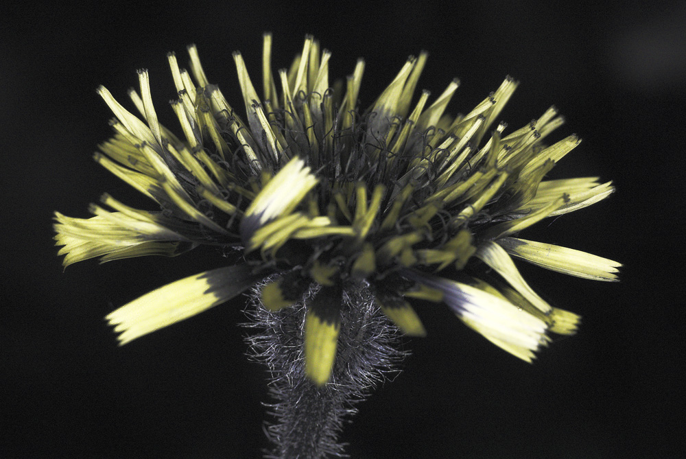
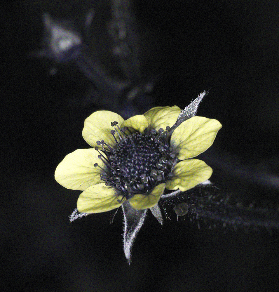
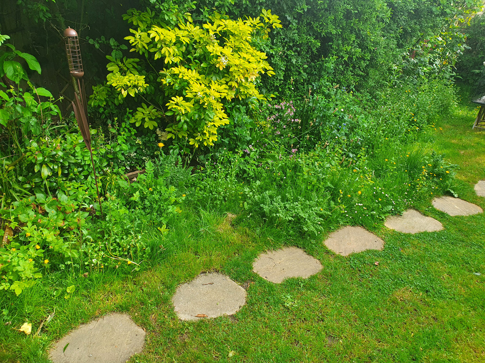
I decided to get some test shots with this using my UV modified Nikon d810 and Rayfact 105mm UV lens – the are UV reflection images (how the plants look in UV, becomes very interesting when we consider that birds and insects can see in UV as well as in visible light). The subjects were wild flowers in the garden. Background lighting was mixed – daylight, but mixture of sunshine and shade. ISO2500, 1/125s exposure, aperture was f11 to f22, white balanced in Darktable and reduced in size for sharing here. Some processing in Photoshop (denoise, curves and sharpening). On to the photos;
These were all within about a 2m stretch of wildflowers in our back garden;
The flash has done a good job of providing additional UV, and the short duration of the flash helps to freeze the subject. The setup is shown below;
The original images are still a little noisy for my liking. The R1C1 flash modules output is not huge in the UV, even with using 4 of them. However for closeup work like this it allowed for ISO2500 with a reasonably depth of field on the lens, which is just provides usable results. With a more recent camera with better high ISO capability ISO2500 would be no issue at all. This then makes for a compact and very usable setup for capturing UV photos of flowers in the field.
Thanks for reading today’s photogenic tale, and if you’d like to know more about this or other aspects of my work, I can be reached here.
I recently wrote about a fascinating little microscope slide from Horace Dall, who coated diatoms in titanium dioxide to help make them more visible for microscopy (you can read about that here). Today’s post shows some new images of the diatoms on the slide, this time taken at high magnification in visible light, using a white light LED light source. I also share the objective I used for the images, as that too is an interesting piece.
On with the images. This were taken using an unmodified Canon EOS 5DS R camera. Condenser was an Olympus Aplanat, set to about NA 1.25 and offset slightly to provide oblique lighting. This was oiled to the underside of the slide. The objective was a Leitz PL APO 100x NA 0.60 to 1.32 (wide open at NA 1.32), which was oiled to the top of the slide. Images reduced in resolution for sharing here, as the EOS 5DS R produce 50Mp images. The colours are as captured, and there is no stacking here, these are single images.
Diatom image with Leitz 100x PL APO objectiveDiatom image with Leitz 100x PL APO objectiveDiatom image with Leitz 100x PL APO objectiveDiatom image with Leitz 100x PL APO objectiveDiatom image with Leitz 100x PL APO objectiveDiatom image with Leitz 100x PL APO objectiveDiatom image with Leitz 100x PL APO objective
And to give you an idea of the original image resolution, here is a cropped part of the image above, shown at the original pixel resolution.
Cropped diatom image with Leitz 100x PL APO objective, original resolution
Some pretty psychedelic colours going on with the TiO2 coating of the diatoms.
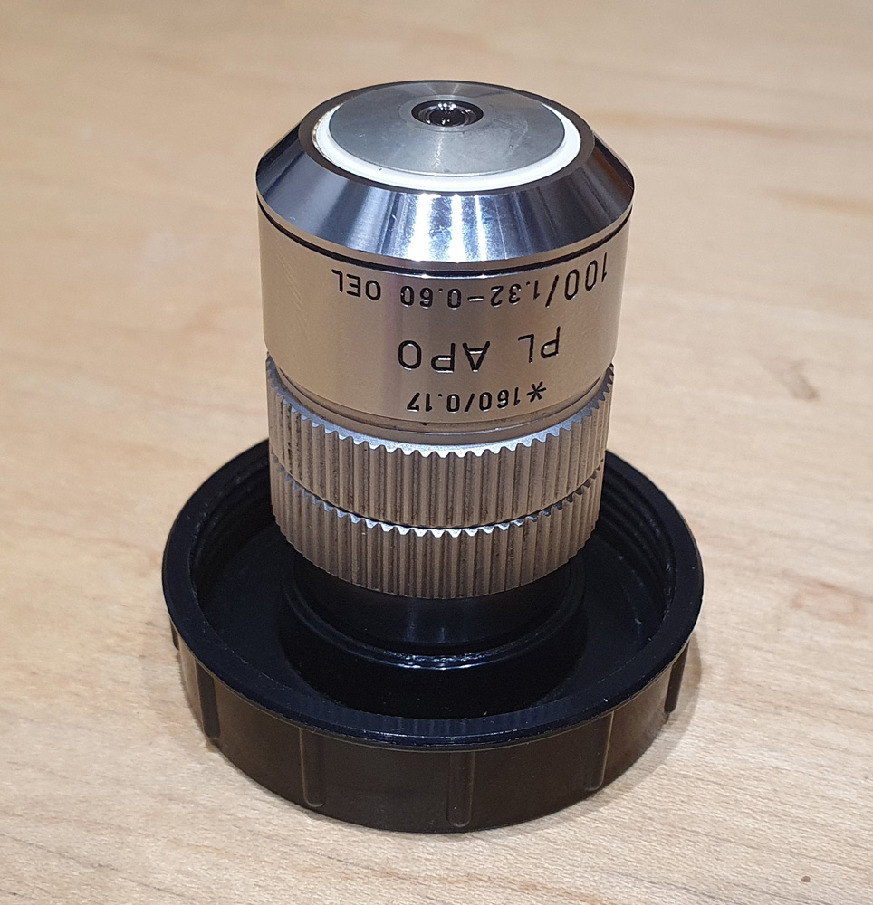
As can be seen with the images the objective provided plenty of resolution, easily resolving features down to well under a micron even with using this visible light source. The objective is a Leitz 100x PL APO NA 0.60-1.32 oil immersion lens as shown below.
What can we tell from the name. 100 means it is 100x magnification, PL means plan (flat image) and APO means it is apochromatic, so it is designed so that three different wavelengths of light all meet at the same focal point, minimizing chromatic aberration. It is oil immersion (‘Oel’) and is for 160mm finite tube length microscopes. It also has a variable aperture, allowing it to be used from NA 0.6 to 1.32. With the images shared here it was used at NA 1.32, but being variable makes it ideal for darkfield imaging, so is a very useful feature. All in all a very capable objective.
This post is a brief one, building on previous work, so I shall leave it there for now. Thanks for reading, and if you’d like to know more about this or any other aspect of my work you can reach me here.