While imaging science is an area I actively research, I’m in the position of having access to some great and unusual photography gear and sometimes it is nice just to get out and enjoy it. I was recently approached by Simon of Simon’s Utak fame on Flickr (link to his profile here). Simon is a great photographer and a huge Takumar fan and was interested in coming to see and use one of the rarest Takumars – the 85mm f4.5 Ultra Achromatic Takumar. This diminutive little lens packs a real punch, and having no glass in it all (the elements are quartz and calcium fluoride) is capable of imaging from the deep UV, through the visible and well into the IR, and is something I have used for my UV imaging. I personally think it is great to share experiences with these almost mythical pieces of photographic history so I invited him over for a photo day and to swap stories.
This is one of his photos of the lens (Flickr post here) taken using another of my more unusual lenses he was keen to try out – a Zeiss Ultron 50mm f1.8;
Asahi 85mm Ultra achromatic takumar on Pentax K-1, Simon Utak, 2022.
Simon is starting to share his images now, which he took on his un-modified, visible light cameras, and you can see the first of them here.
Thanks for reading, and if you’d like to know more about this or other aspects of my work, I can be reached here.
When I started UV imaging of sunscreens about 5 years ago, I ended up having to get various bits of kit to try, not knowing what would work and what wouldn’t. This is normal when building new imaging methods, as it is difficult to predict what will work and what wont. One lighting setup I got at the time was a UV modified Nikon R1C1 flash system. Advanced Camera Services Ltd here in the UK (where I bought the UV modified camera from) replaced the flash windows with UV transparent material which also blocked the visible light. At the time, I assumed that I needed the flashes to be visible blocking rather than just leave them as emitting everything for UV imaging which turned out not to be correct. However, the other lighting I got worked for the project, and this modified R1C1 has sat in a box ever since. Until a few days ago.
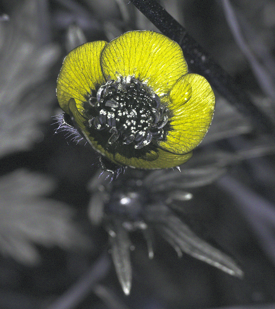
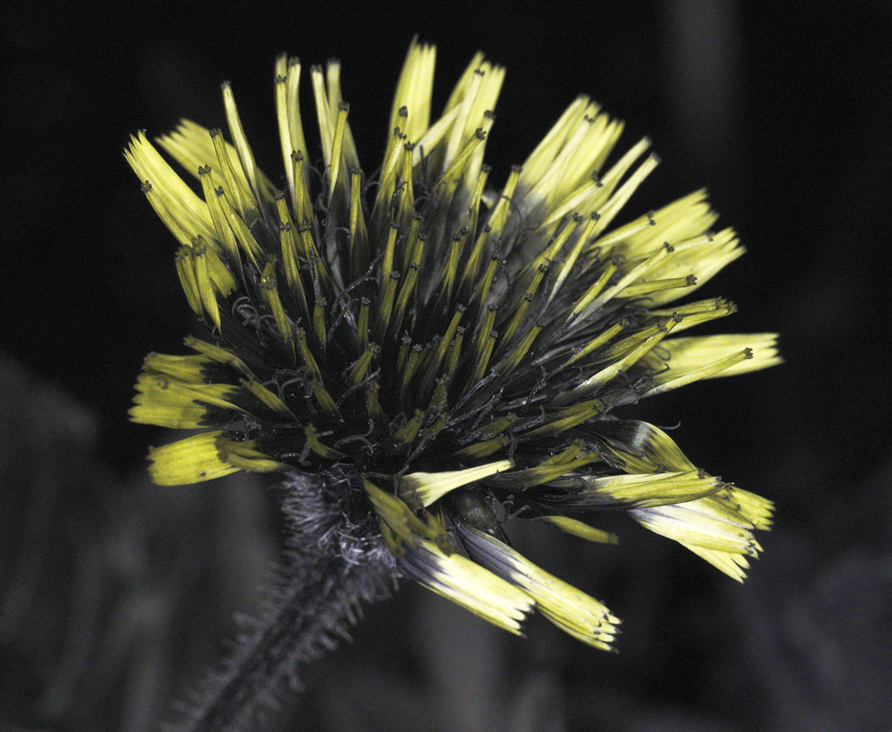
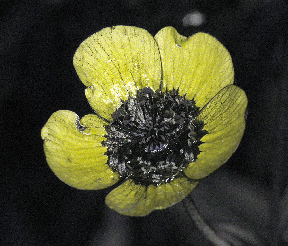
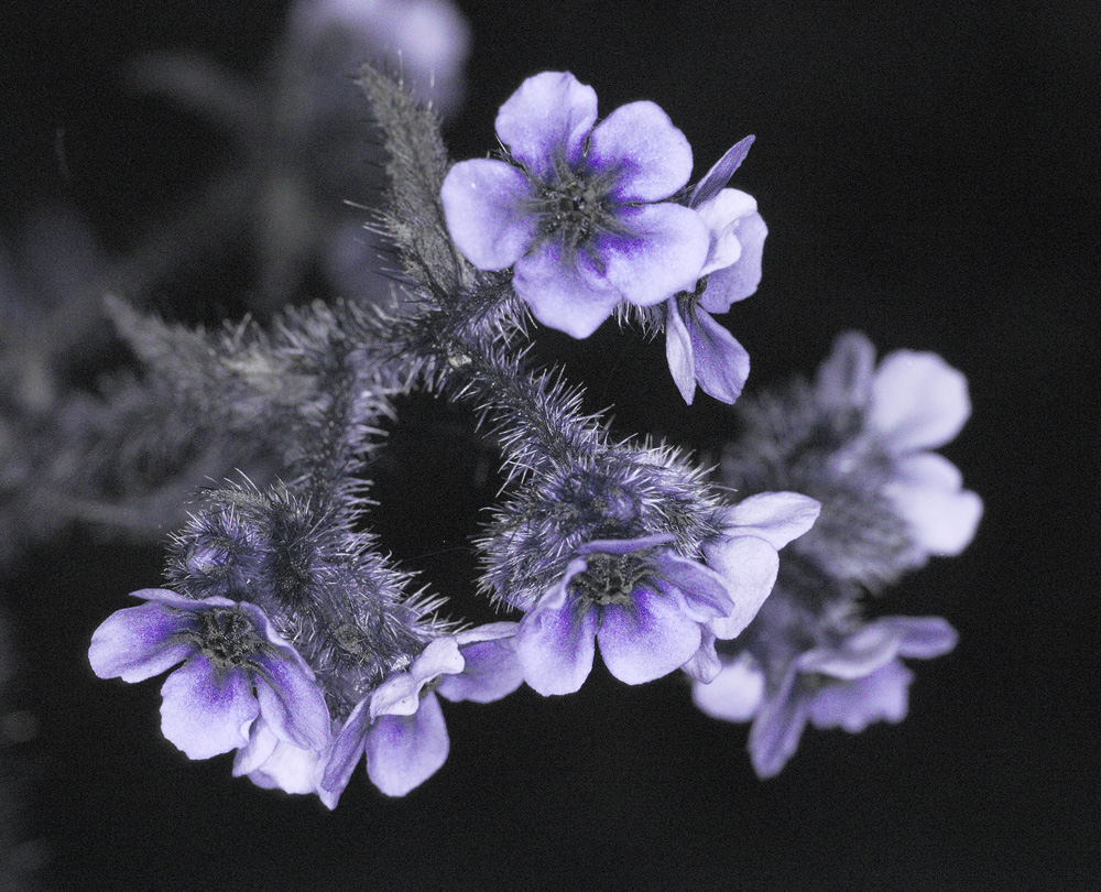
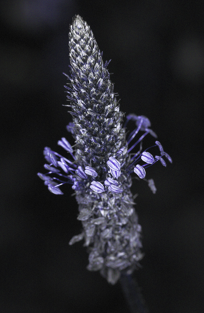
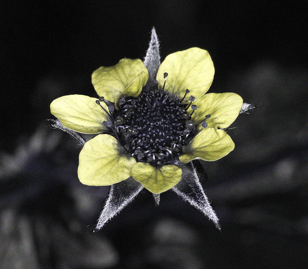
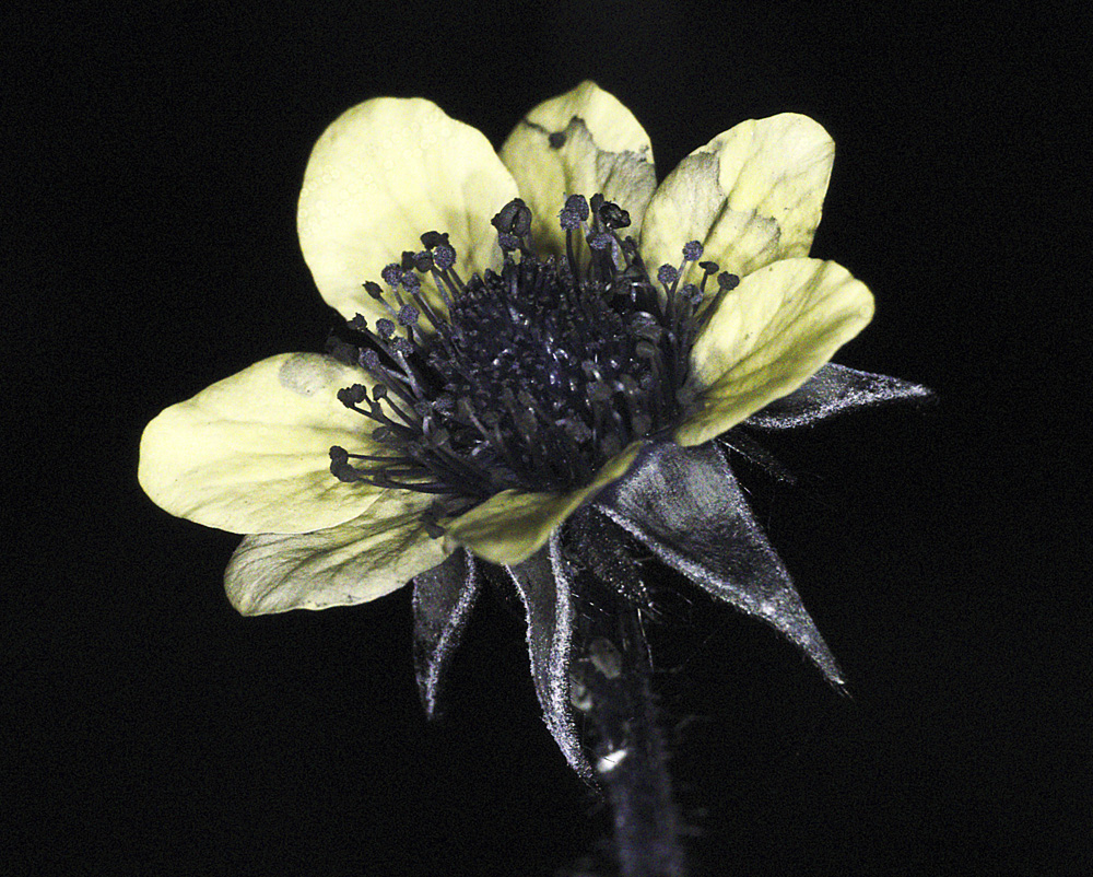
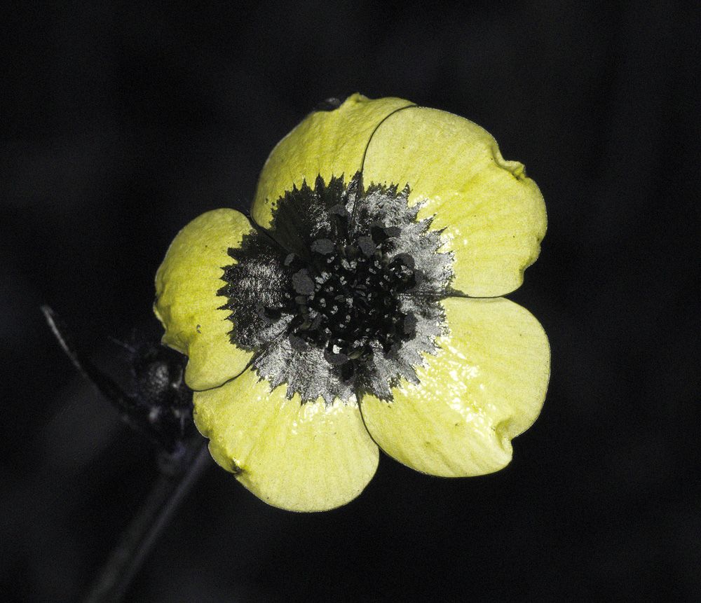
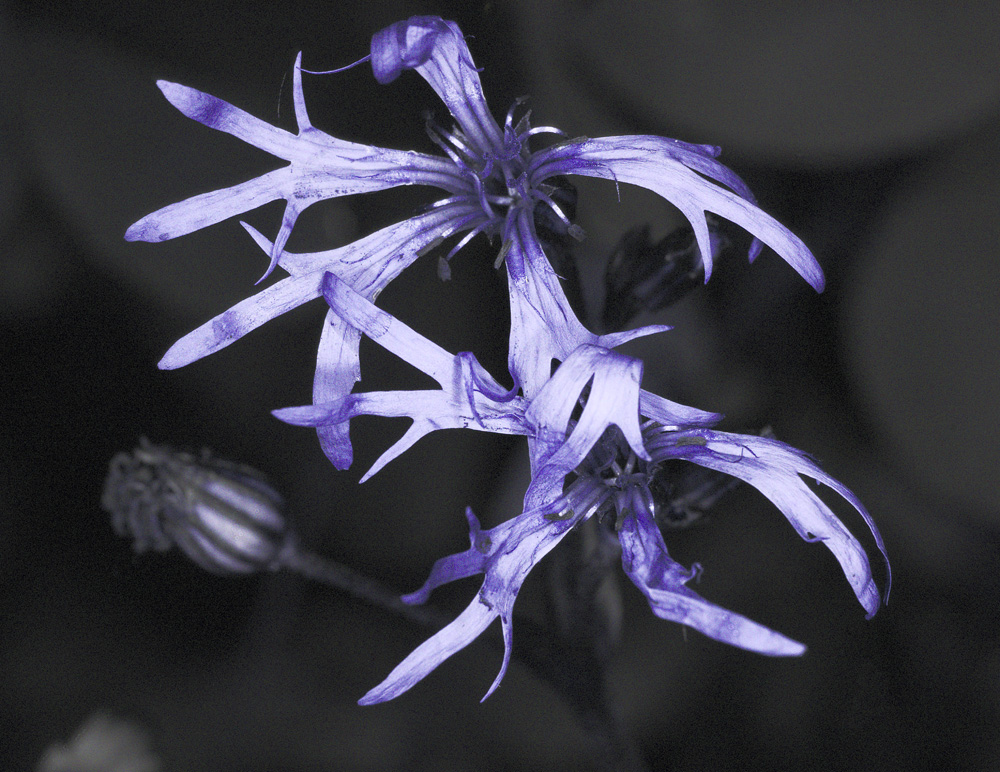
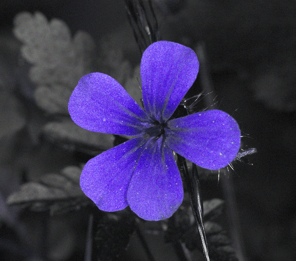
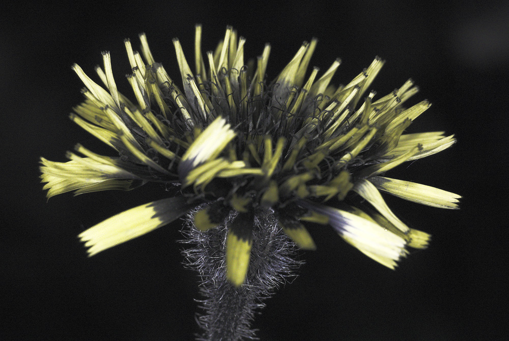
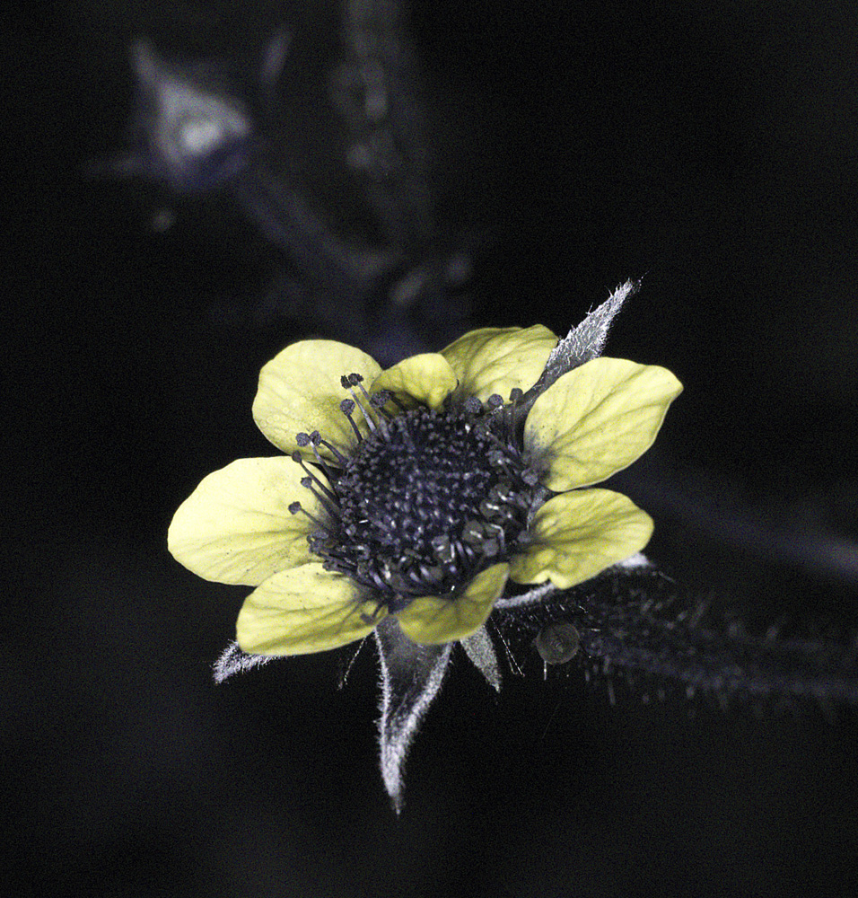
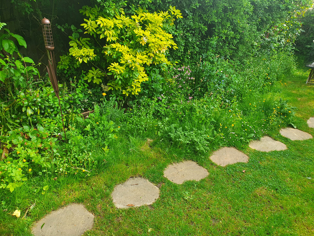
I decided to get some test shots with this using my UV modified Nikon d810 and Rayfact 105mm UV lens – the are UV reflection images (how the plants look in UV, becomes very interesting when we consider that birds and insects can see in UV as well as in visible light). The subjects were wild flowers in the garden. Background lighting was mixed – daylight, but mixture of sunshine and shade. ISO2500, 1/125s exposure, aperture was f11 to f22, white balanced in Darktable and reduced in size for sharing here. Some processing in Photoshop (denoise, curves and sharpening). On to the photos;
These were all within about a 2m stretch of wildflowers in our back garden;
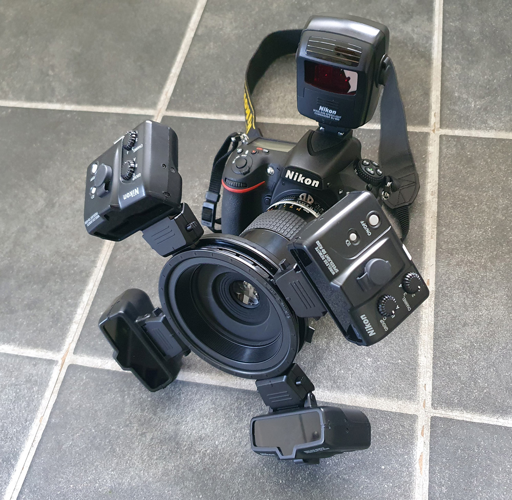
The flash has done a good job of providing additional UV, and the short duration of the flash helps to freeze the subject. The setup is shown below;
The original images are still a little noisy for my liking. The R1C1 flash modules output is not huge in the UV, even with using 4 of them. However for closeup work like this it allowed for ISO2500 with a reasonably depth of field on the lens, which is just provides usable results. With a more recent camera with better high ISO capability ISO2500 would be no issue at all. This then makes for a compact and very usable setup for capturing UV photos of flowers in the field.
Thanks for reading today’s photogenic tale, and if you’d like to know more about this or other aspects of my work, I can be reached here.
I recently wrote about a fascinating little microscope slide from Horace Dall, who coated diatoms in titanium dioxide to help make them more visible for microscopy (you can read about that here). Today’s post shows some new images of the diatoms on the slide, this time taken at high magnification in visible light, using a white light LED light source. I also share the objective I used for the images, as that too is an interesting piece.
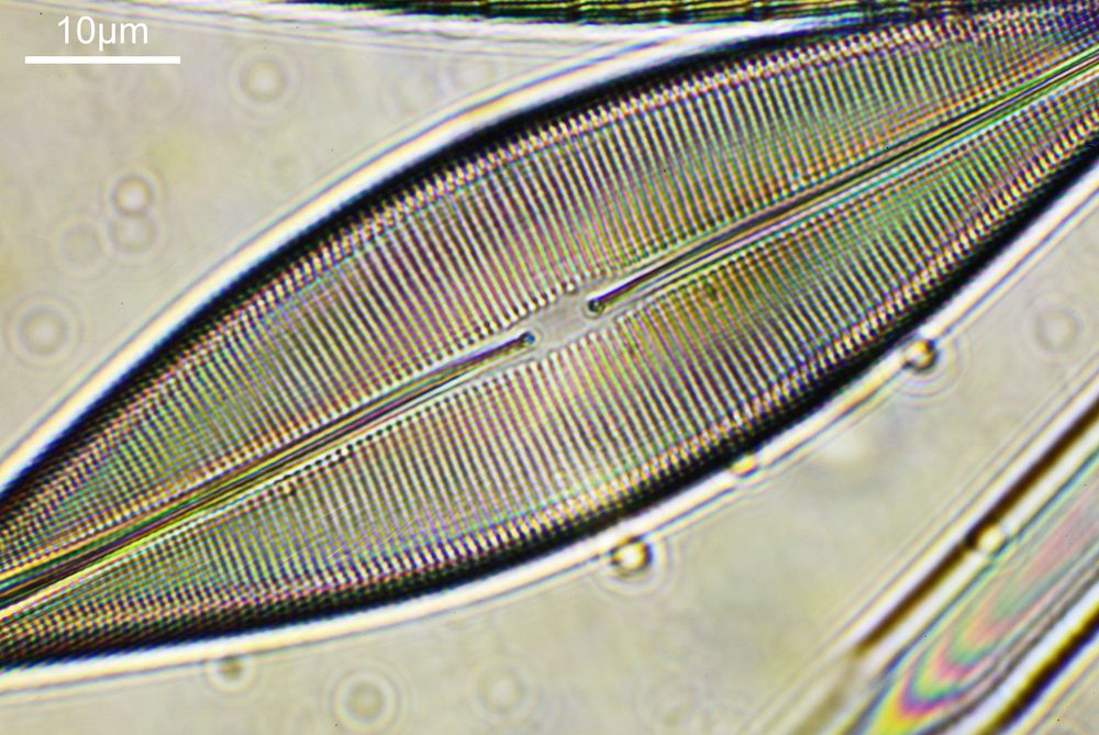
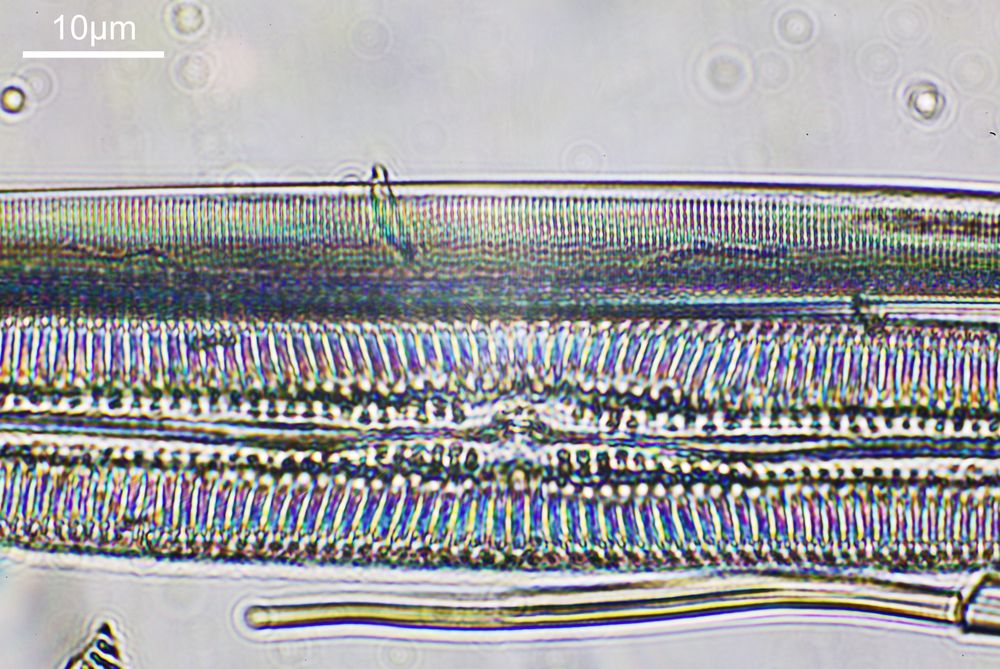
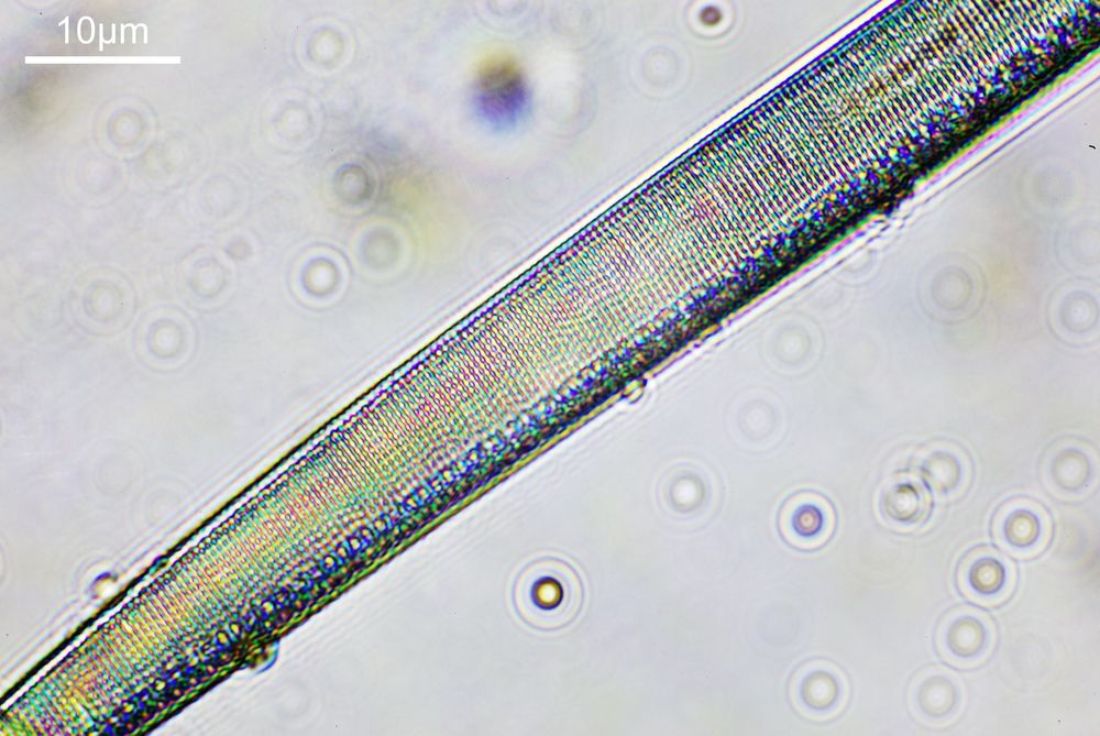
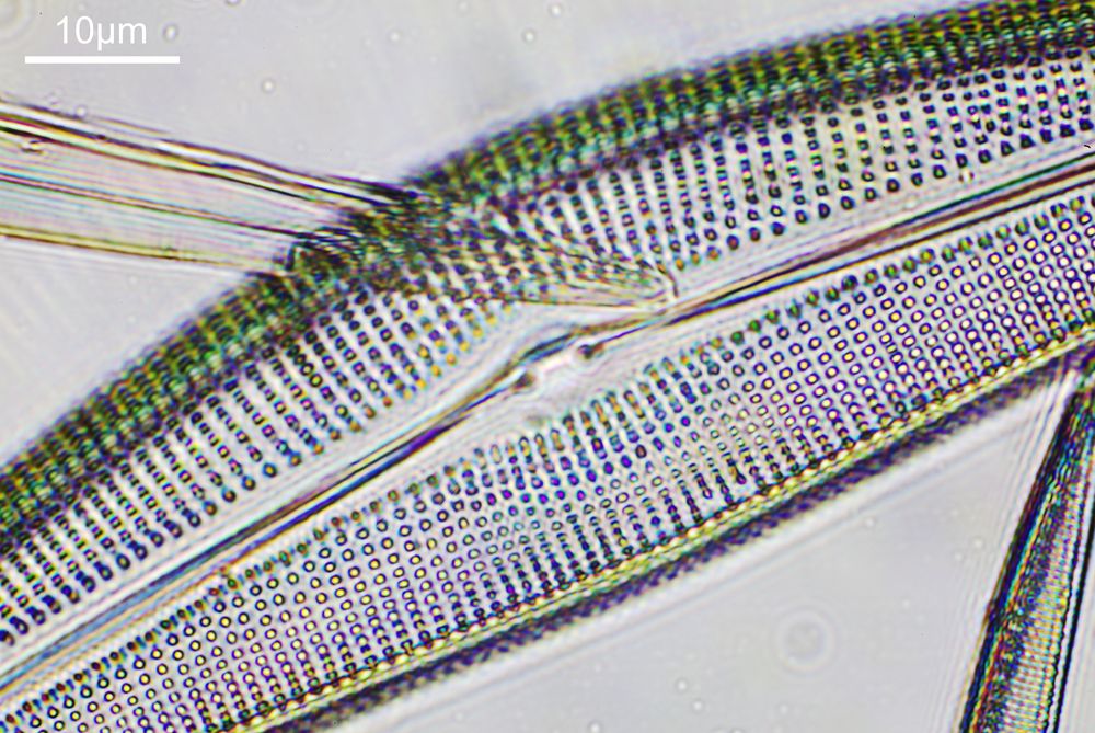
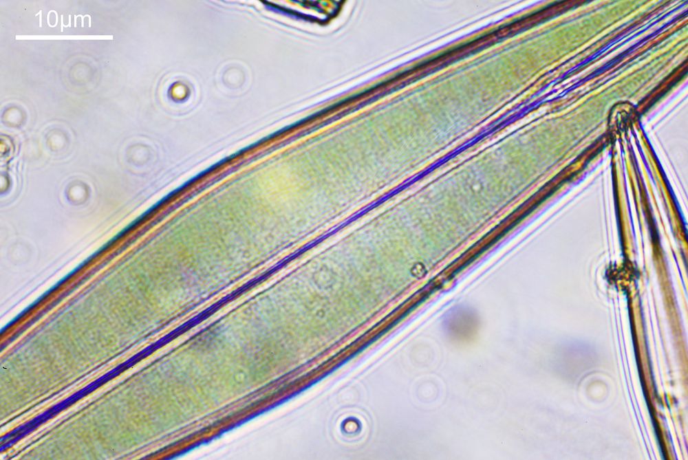
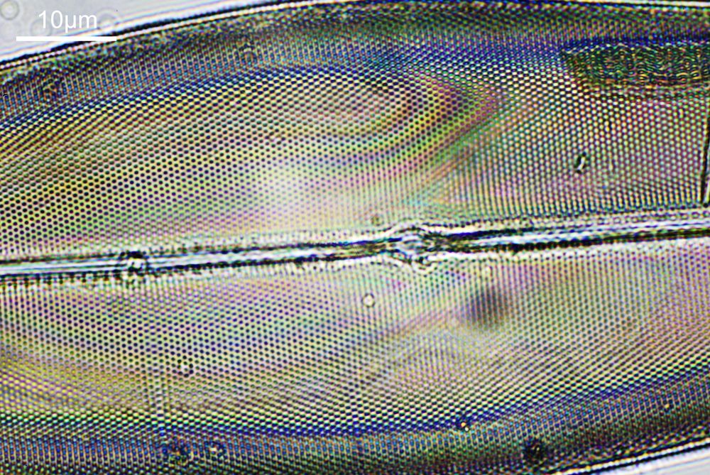
On with the images. This were taken using an unmodified Canon EOS 5DS R camera. Condenser was an Olympus Aplanat, set to about NA 1.25 and offset slightly to provide oblique lighting. This was oiled to the underside of the slide. The objective was a Leitz PL APO 100x NA 0.60 to 1.32 (wide open at NA 1.32), which was oiled to the top of the slide. Images reduced in resolution for sharing here, as the EOS 5DS R produce 50Mp images. The colours are as captured, and there is no stacking here, these are single images.
Diatom image with Leitz 100x PL APO objectiveDiatom image with Leitz 100x PL APO objectiveDiatom image with Leitz 100x PL APO objectiveDiatom image with Leitz 100x PL APO objectiveDiatom image with Leitz 100x PL APO objectiveDiatom image with Leitz 100x PL APO objectiveDiatom image with Leitz 100x PL APO objective
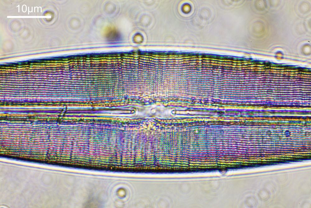
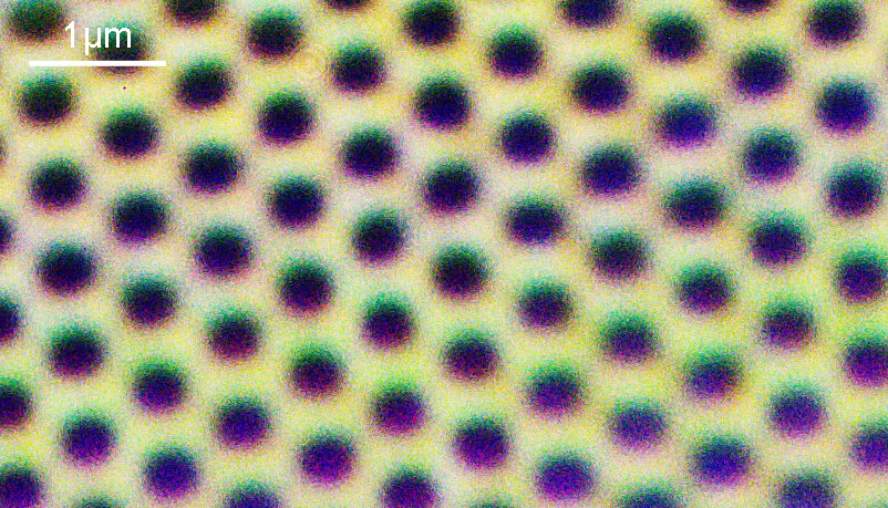
And to give you an idea of the original image resolution, here is a cropped part of the image above, shown at the original pixel resolution.
Cropped diatom image with Leitz 100x PL APO objective, original resolution
Some pretty psychedelic colours going on with the TiO2 coating of the diatoms.
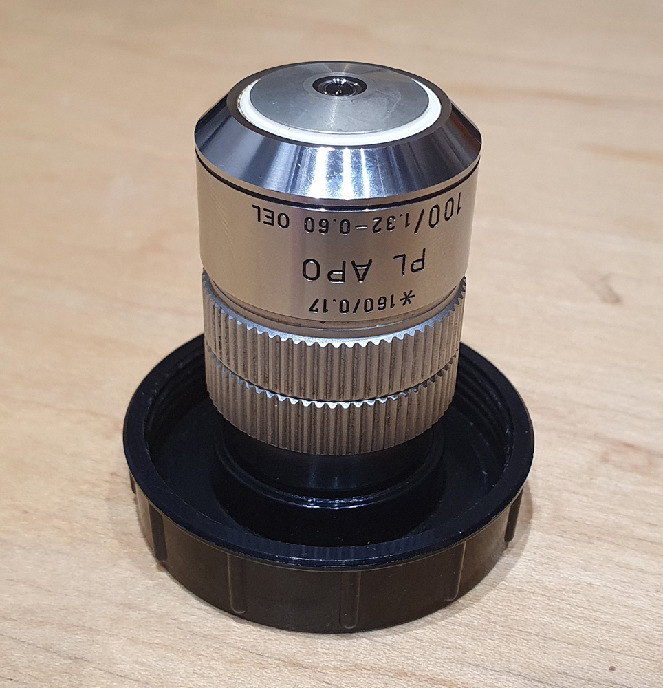
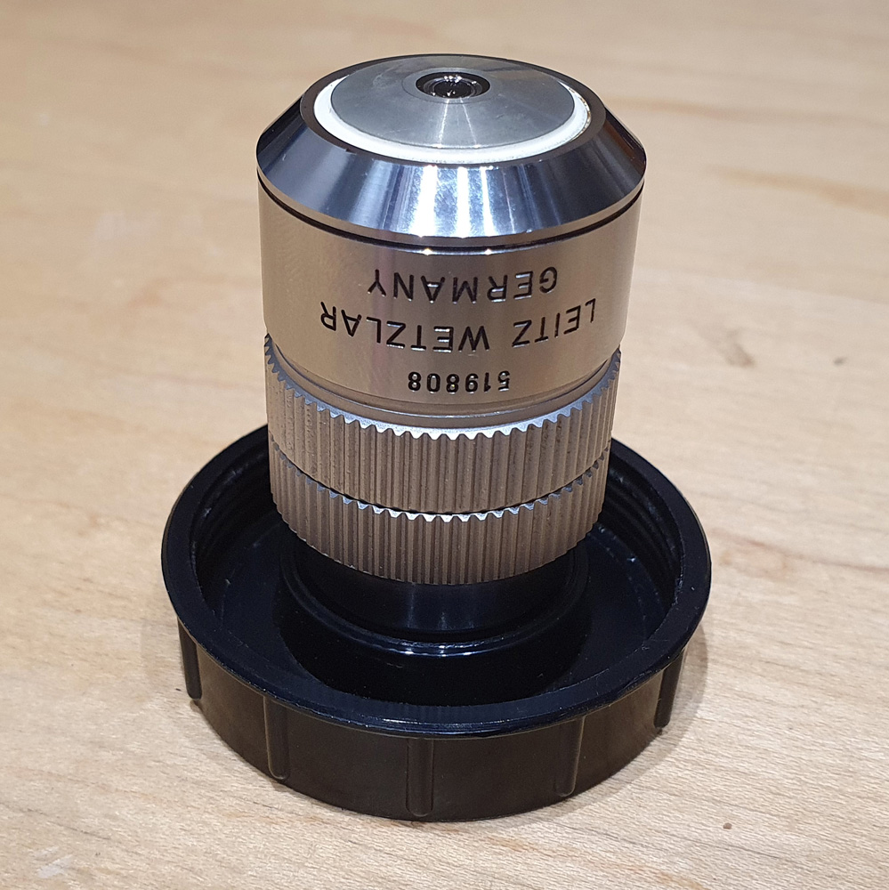
As can be seen with the images the objective provided plenty of resolution, easily resolving features down to well under a micron even with using this visible light source. The objective is a Leitz 100x PL APO NA 0.60-1.32 oil immersion lens as shown below.
What can we tell from the name. 100 means it is 100x magnification, PL means plan (flat image) and APO means it is apochromatic, so it is designed so that three different wavelengths of light all meet at the same focal point, minimizing chromatic aberration. It is oil immersion (‘Oel’) and is for 160mm finite tube length microscopes. It also has a variable aperture, allowing it to be used from NA 0.6 to 1.32. With the images shared here it was used at NA 1.32, but being variable makes it ideal for darkfield imaging, so is a very useful feature. All in all a very capable objective.
This post is a brief one, building on previous work, so I shall leave it there for now. Thanks for reading, and if you’d like to know more about this or any other aspect of my work you can reach me here.
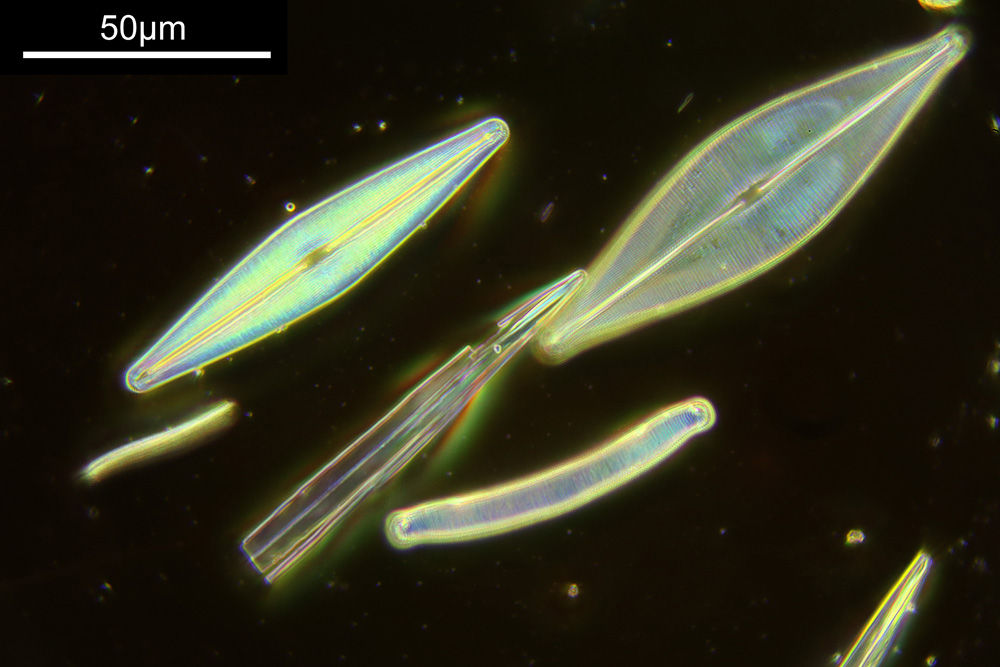
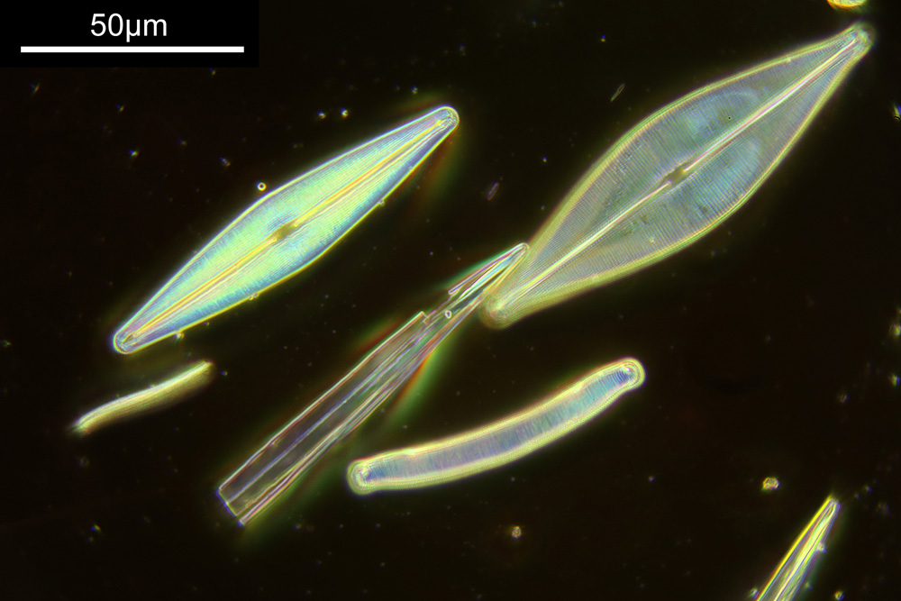
Sometimes I see something for sale, and despite not knowing quite why, know that it’ll be interesting or useful to have. So it was the other day when I saw a microscope slide for sale. This was a diatom slide made in 1950 by a chap called Horace Dall, but what caught my eye was that the slide said that the diatoms were mounted in titanium dioxide (TiO2), and then it gave a refractive index measurement – ‘µ = 2.90’. Before I show you the slide though, I want to share an image taken of it, as it turns out it makes for some really spectacular photos.
63x darkfield image from the Horace Dall titanium dioxide mounted diatom slide
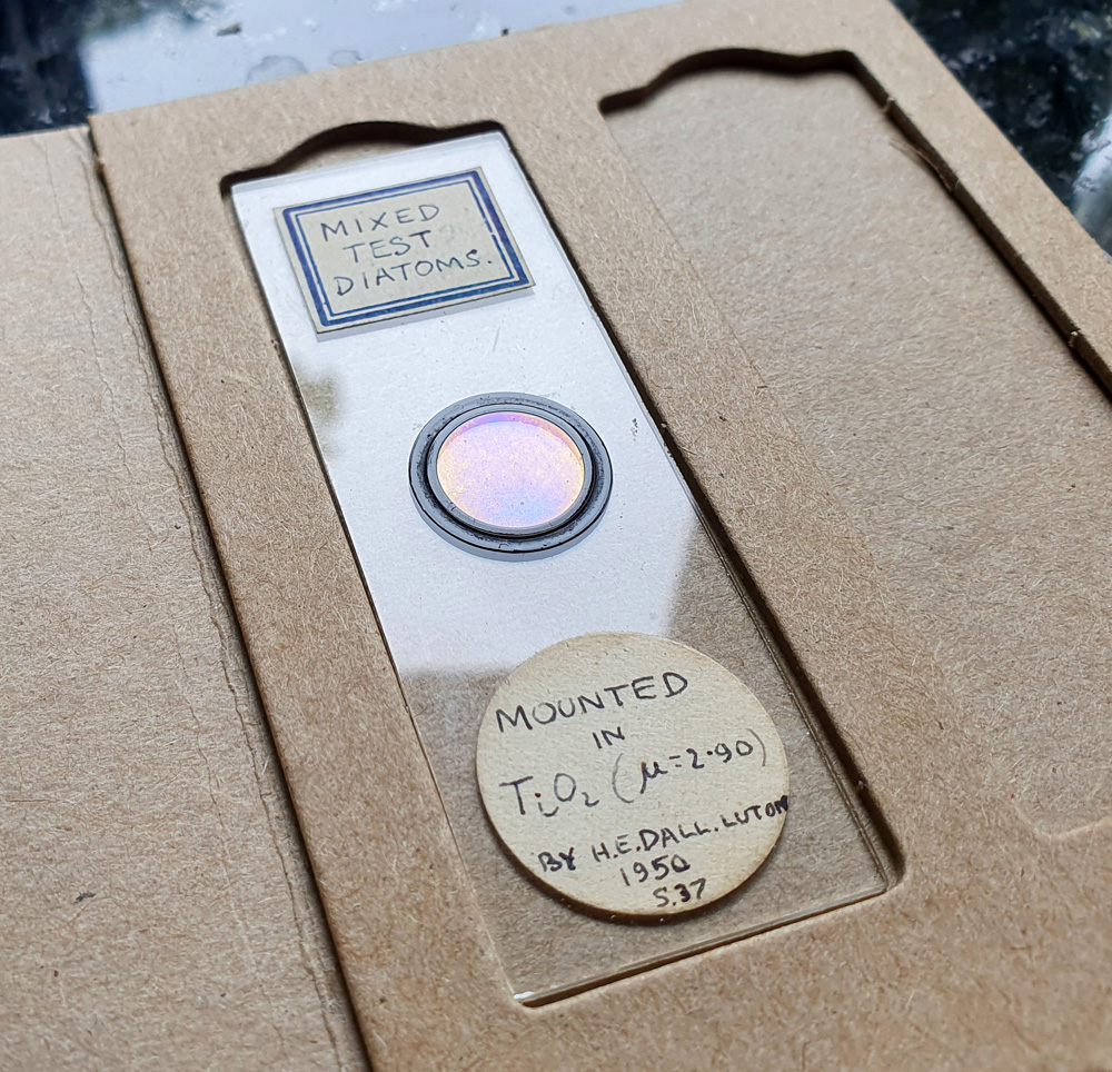
I’ll speak more about the images from it in a minute. Back to the slide itself. Here’s a photo of the slide;
Horace Dall diatom slide, mounted in Titanium Dioxide
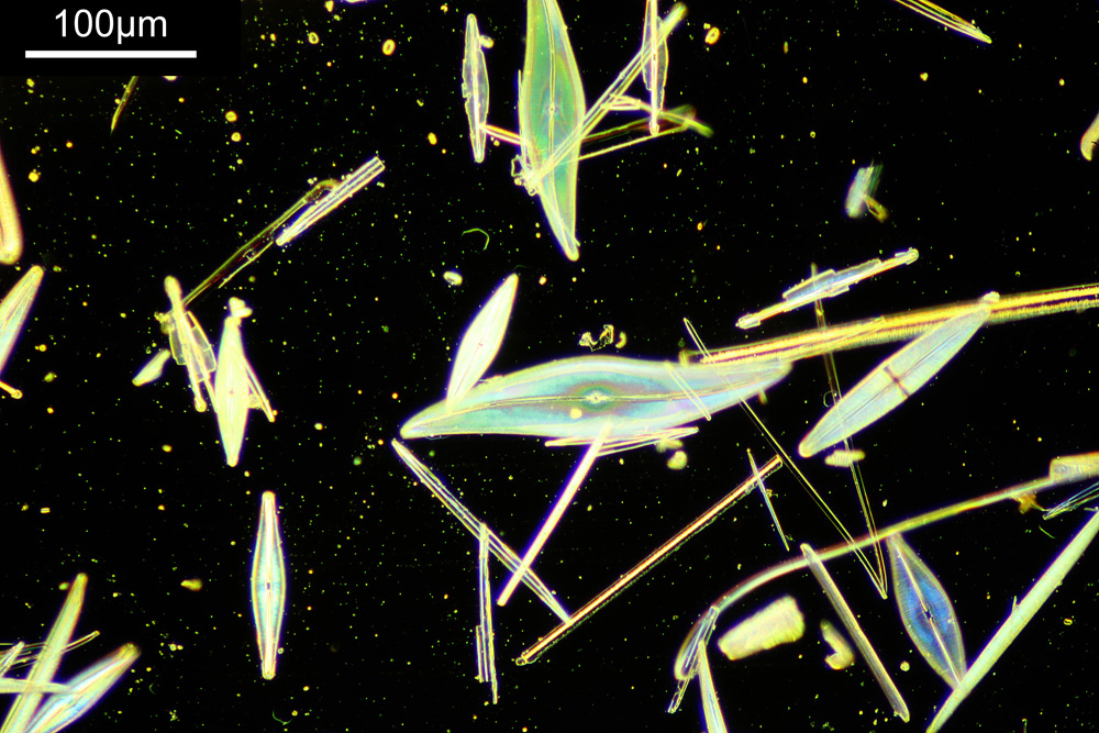
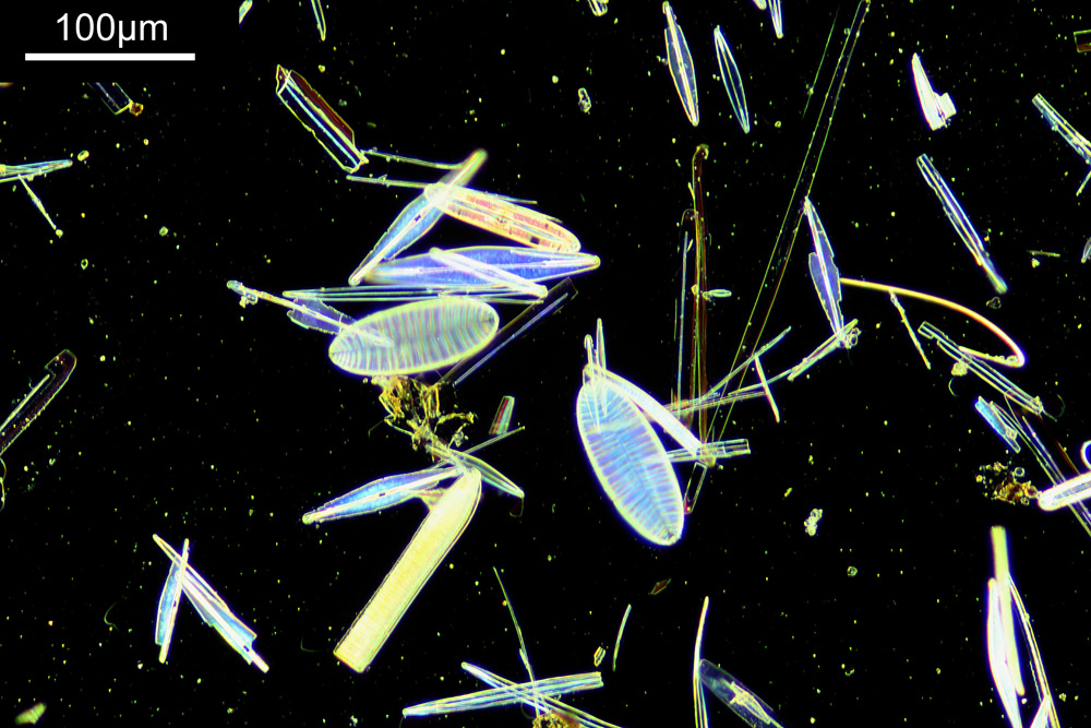
I’d not seen anything like this before, and guessed that it had been done to improve contrast of the diatoms for imaging (given the high refractive index of the TiO2). The sample under the coverslip had a sheen to it a bit like an oil film on water. After a bit of a bidding war I ended up with it and the imaging began. As a simple set of initial images I did some brightfield and darkfield ones with a 20x objective (Olympus Splan 20x) and a 63x objective (Zeiss Neofluar Pol 63x) as I could use both of these without needing to mess around with immersion fluids. Images were captured using a white LED light, and with a normal unmodified colour camera. The colours you see below have not been modified by me, these are as captured by the camera. Anyway, less chat, more images;
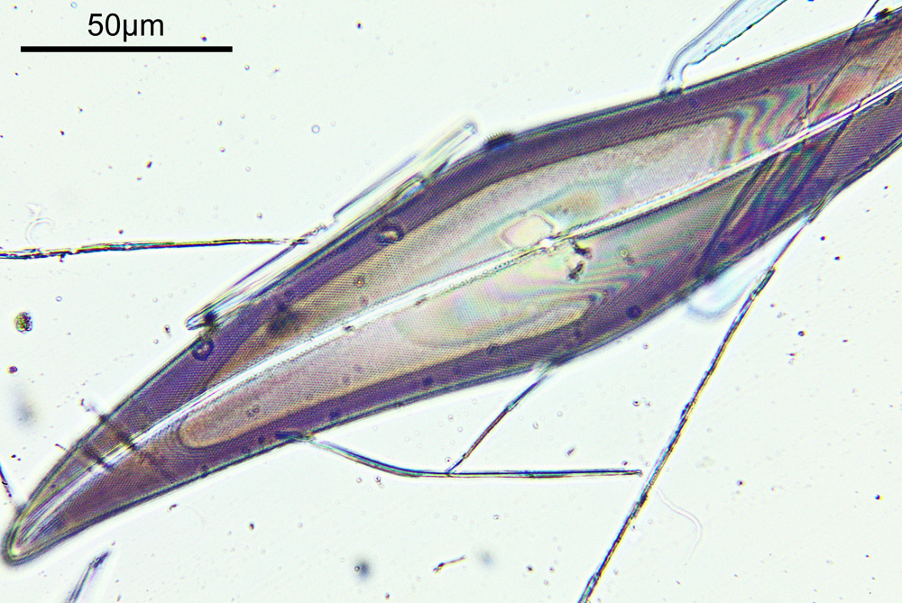
20x darkfield image20x darkfield image63x darkfield image (the same one as shared at the beginning of the article)63x brightfield image
The darkfield images especially were very pretty, showing a range of colours from blue through to red for different diatoms. Even the brightfield image showed the range of colours. The effects reminded me a bit of looking at mica particles which are put in cosmetics, or an oil film on water, and I presume this is due to the thin layer of TiO2 deposited on the diatoms causing interference colours. This led me to wondering whether anything had been published on this process or these samples. I spend my days tracking down information on stuff, so set about looking for details on this, and, ……..nothing. So I approached the Facebook group of the Quekett Microscopical Club that I am a member of, and within an hour loads of useful information came back, including reference to a paper in the Quekett Journal from 1985 written by Horace Dall about making these types of slides. So, I need to learn more about searching for information….
Horace made these slides by exposing them to fuming titanium tetrachloride, which was then transformed into TiO2. Back when I was a student in Durham I won the Tioxide Scholarship for the year during my Chemistry degree. This came with a trip around the Tioxide plant on Teesside, where I was given horror stories about titanium tetrachloride and how dangerous it is. In Horace’s paper, he mentions “These experiments were carried out only when suitable winds would quickly evacuate the fumes.”. Legend. After this he went on to develop other approaches including the evaporation of aluminium (or aluminum for some readers) in a vacuum and using that instead. This brings me to another interesting point. I searched for information on this and found a number of articles which discussed coating diatoms with metal and metal oxide films for different purposes. None of them that I have found so far have referenced Horace Dall’s work though, despite being done many years afterwards. Horace was many years ahead of of his time with some of his work.
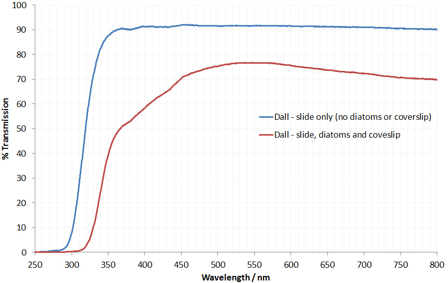
As this process was done to improve resolution, it got me wondering whether I could try imaging with UV as my previous work has shown how this improves resolution (see here). However I assumed that the slide was made of glass, so it likely wouldn’t be feasible to image all the way down at 313nm. It did make think that 365nm may be possible. Out came the Ocean Insight spectrometer, and I measured the transmission spectra through the slide itself and then through the slide/diatoms/coverslip, and got the following;
The slide itself is glass, and the transmission drops below 350nm, down to about 290nm where it becomes opaque. The region with the diatoms and coverslip though absorbed quite a lot of light at all wavelengths, but in the UV, transmission fell down to about 320nm. As I expected imaging at 313nm wouldn’t be possible, but 365nm would be doable. The transmission curves are interesting. The coverslip is likely the same type of glass as the slide, and is much thinner than the slide. Therefore it should block less of the UV. The shape of curve is likely driven by the TiO2 layer, as it does block short wavelength UV.
I went back to the slide and managed to find the same region I imaged with one of the darkfield images (the 63x one). This time though I imaged it in brightfield at 365nm with my Leitz 100x NA 1.2 glycerine immersion objective, and got the following image.
365nm brightfield image from the Horace Dall diatom slide
Just for comparison here’s a crop of the 63x darkfield image showing the same diatom.
Crop of 63x darkfield image
The 365nm brightfield image has slightly better resolution than the darkfield image, which is not a huge surprise – better objective with a higher NA (1.2 vs 0.9), and used a shorter wavelength of light, but some of the structures visible in the 365nm are still visible in the darkfield visible light image.
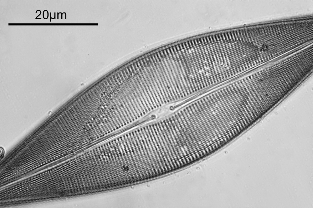
Just for giggles, here’s a crop of the 365nm darkfield image, looking at the pore structure of the diatom.
Crop of the 365nm brightfield image showing the diatom pore structure
Even with 365nm it looks as though I am getting down to well below a micron in terms of the features being resolved. Keep in mind that the slide and coverslip were glass (not quartz) and the coverslip thickness was also wrong for the objective, so although this may not be as sharp as it could have been, it is still a respectable result.
It’s funny how a single historical sample can be such a fascinating thing to image. It is all too easy to forget, or just not realise, that amazing scientists existed before the days of the internet, and it can be hard to track down their work if you don’t know exactly what you are looking for. I can feel a new paper coming on looking at some of Horace Dall’s work as he was such a pioneer, and bring it to a whole new generation of scientists. If you’ve made it this far, thanks for reading, and if you’d like to know more about this or any other aspect of my work, you can reach me here.
“Few objects are more beautiful than the minute siliceous cases of the diatomaceae: were these created that they might be examined and admired under the higher powers of the microscope? The beauty in this latter case, and in many others, is apparently wholly due to symmetry of growth…”, Charles Darwin, On the Origin of Species, 1866.
While I spend a lot of my time doing research for other people, I am also a simple scientist at heart. Like many people I appreciate beauty in art, but for me, I tend to seek patterns and structure in what I am looking at. Something that gives me both beauty and structure is looking at diatoms under the microscope. These are the solid structures left behind when certain species of algae die off and they are beautiful structures. I’ve not graduated to making my own microscope slides just yet, so tend to keep an eye out for second hand ones on eBay. Some can be had for a few GBP (although for big arrangements you can pay thousands of GBP, especially from certain makers as there is a big collectors market) and they make for fascinating viewing under the microscope at the end of a long week – microscope therapy as it were. Today I want to share with you some images from a couple of slides which arrived this week.
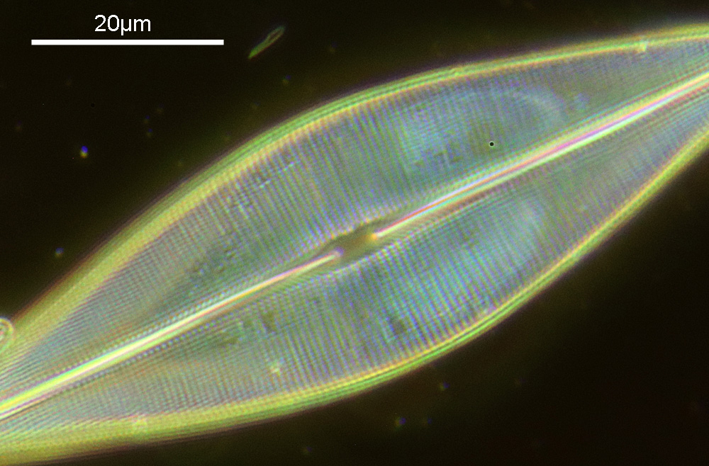
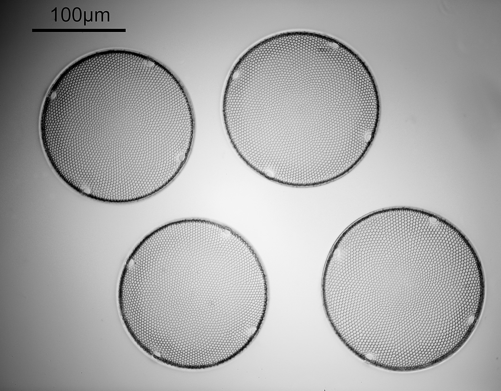
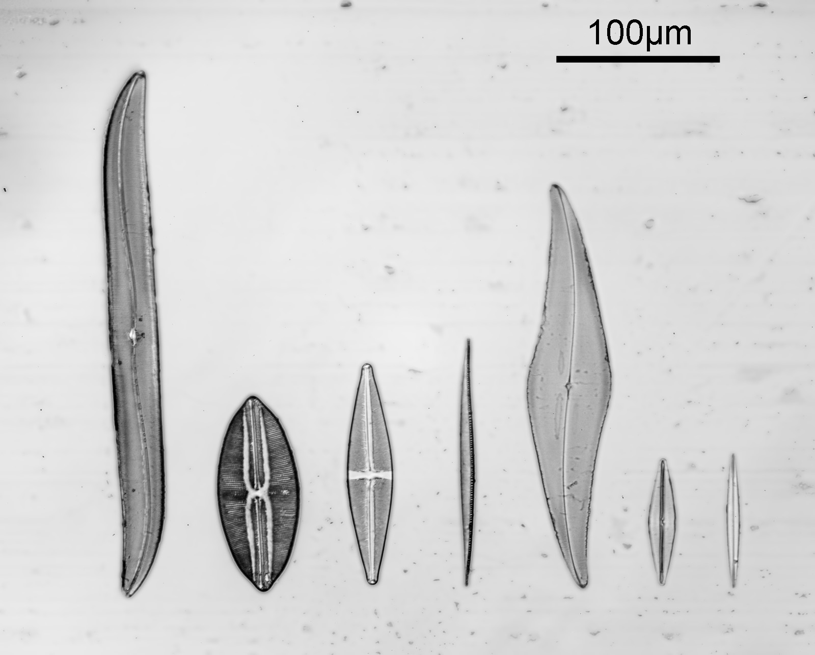
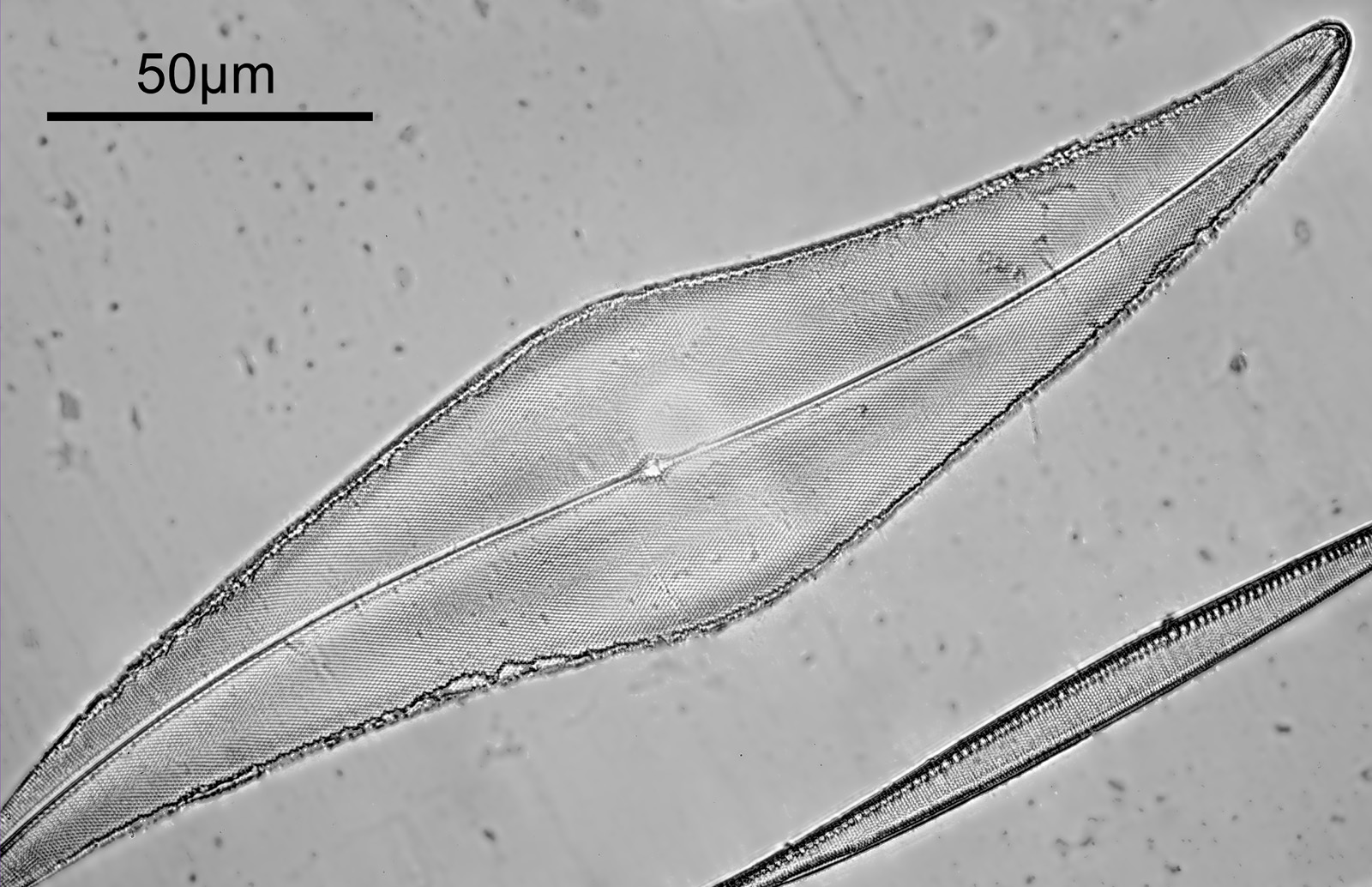
Two slides arrived this week – one is an antique slide made by John Barnett which has an arrangement of 4 examples Eupodiscus radiatus diatoms, the other is a 7 form test slide made by Klaus Kemp. Low magnification images (using an 20x Olympus Splan objective) of the samples on the two slides are shown below.
John Barnett slide which has an arrangement of 4 examples Eupodiscus radiatus diatoms7 form test slide made by Klaus Kemp
The images above where made using 405nm light on my UV microscope. How on earth anyone is able to move an arrange these things on such a small scale amazes me. But it is the structures in the diatoms that become more clearly visible at high magnification which are really fabulous. On the first slide, moving to a 60x objective (Olympus 60x Splan Apo), gives the following.
Closeup of the Eupodiscus radiatus diatom slide
Using the 60x brings me in a little too close for this sample, but it was an objective I wanted to have a play with. Cropping the original image further, allows the structure to be more easily observed.
Crop of the Eupodiscus Radiatus diatom slide
While the majority of the features are hexagonal, there are pentagons and heptagons spread throughout it, which allow the structure to take on the beautiful curves that it has. Not too bad for an algae.
Moving into the Klaus Kemp slide, I decided to look at the one which was third from the right (Pleurosigma angulatum). This one has one nice small features and makes of a good one to look at. Here it is, again with the 60x Olympus Splan Apo objective.
Pleurosigma angulatum from the Klaus Kemp 7 form slide
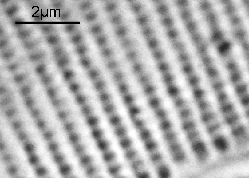
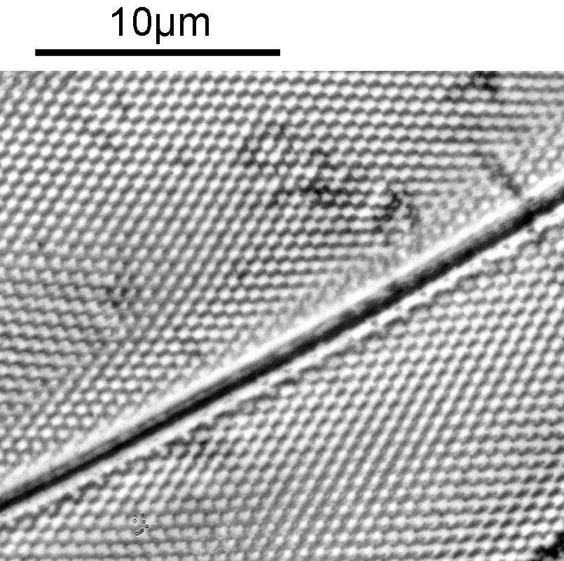
As with the Eupodiscus radiatus, the use of the 60x was slightly too big a magnification for the Pleurosigma angulatum (note to self use a smaller magnification photoeyepiece next time). However this one has some really small features, as can be seen in a cropped image below.
Cropped image of the Pleurosigma angulatum from the Klaus Kemp 7 form slide
The repeating dot like features in the image above have been reported in the literature to have about 16 per 10 microns, and that is indeed what I see here.
I used 405nm light here, as this provides some improvement in potential resolution vs normal white light. Using 405nm gives a nice boost to resolution without all the hassle of going to full UV imaging, and it means being able to use normal slides, coverslips, objectives and condensers. However this time I didn’t quite get the setup right as there is a hotspot in the middle of the 60x images and a bit of fall off in one of the 20x ones. I actually cheated a bit as well and used glycerine as the immersion fluid for the 60x objective, rather than oil. This was due to laziness – its easier to clean off the glycerine than oil – and perhaps I sacrificed a bit of image quality as a result. I also didn’t oil the condenser to the underside of the slide – due to not wanting to make a mess.
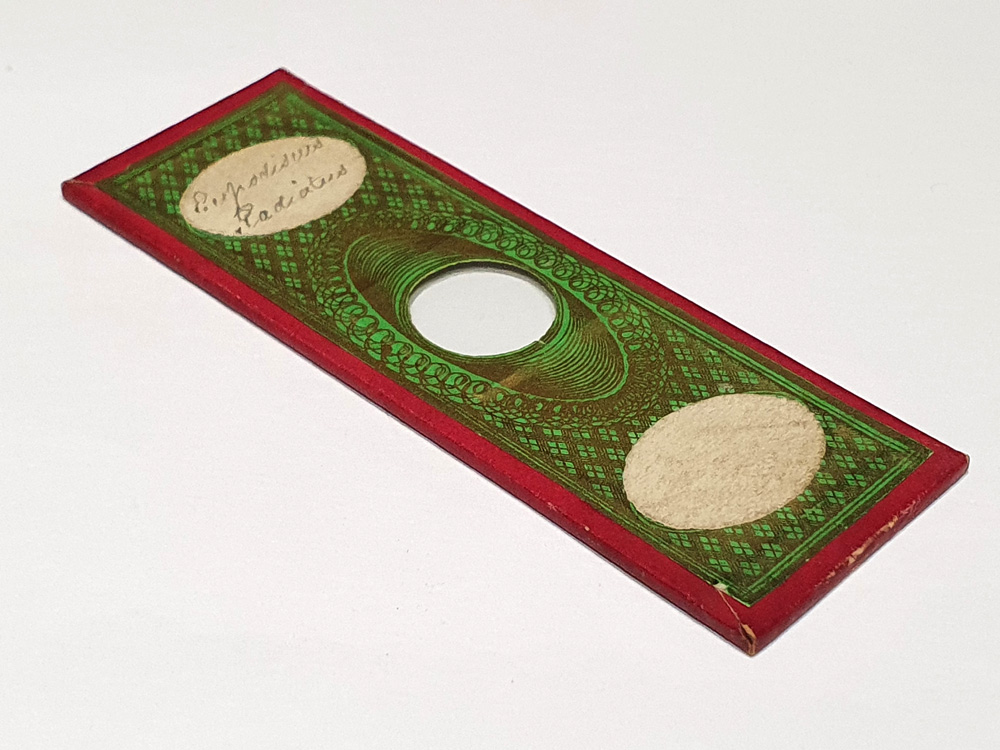
Before I leave todays post, I wanted to share images of the slides themselves. First the antique John Barnett one.
Antique John Barnett diatom slide
The John Barnett slide is actually paper wrapped, and the diatoms are in the middle of the glass in the centre of the slide. They are of course not visible at this scale. Next we have the Klaus Kemp slide.
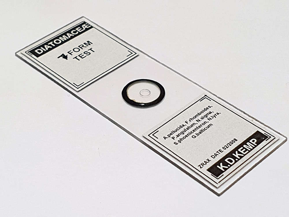
Klaus Kemp 7 form test slide
The Klaus Kemp slide is a simpler affair, and the diatom are inside the small ring in the middle of the slide.
The world of the small can be a beautiful place and for a relatively small outlay is within the reach of anyone with a simple microscope. I’m no expert on diatom imaging (check out the Photomacrography forum for some amazing images) but I just find it endless fascinating to look at them. Thanks for reading and if you’d like to know any more about this or my other work, I can be reached here.
Some photos are just pretty, some are challenging, others are shocking. In the world of research an image, if captured in a controlled way, can provide as much information as any other form of measurement. In some recent work, I presented imaging of a diatom at 313nm on my custom made UV microscope (see here), and one question which came from the work was how could I quantify the resolution of my objectives at different wavelengths of light, including well down into the UV. This brings me to the topic of today’s post – resolution testing of my microscope using the Newport Highres-2 high resolution microscope test slide.
To test my microscope I knew I was going to need a high end test slide – something with very small features. UV microscopy offers improved resolution compared to using visible light, and looking at my previous diatom image taken with the Leitz 100x NA1.2 UV objective at 313nm it seemed like I was resolving features down to about 200nm if not below. I also needed the slide to be made from quartz of fused silica rather than glass, so it wouldn’t block UV. As a final requirement, it needed to be able to be used with immersion oil or glycerin and a coverslip without damaging the test target. Taking all this into account I decided on a Newport Highres-2 positive slide (opaque lines on a clear background), and having spoken with them it looked like this would indeed survive being using with immersion fluid and a coverslip, and would be UV transparent. So I went ahead and ordered one.
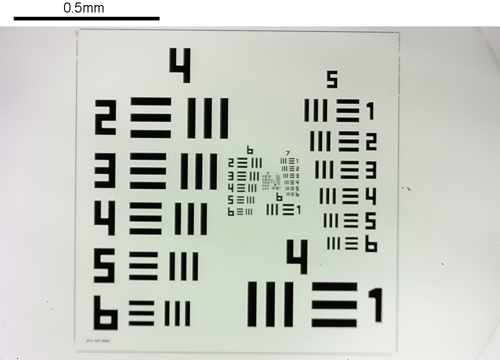
The test slide is a USAF pattern, which has lines of different widths arranged on it. An image of the full area of the test slide taken in visible light using a 4x objective on my microscope is shown below.
Newport Highres-2 microscope resolution test slide
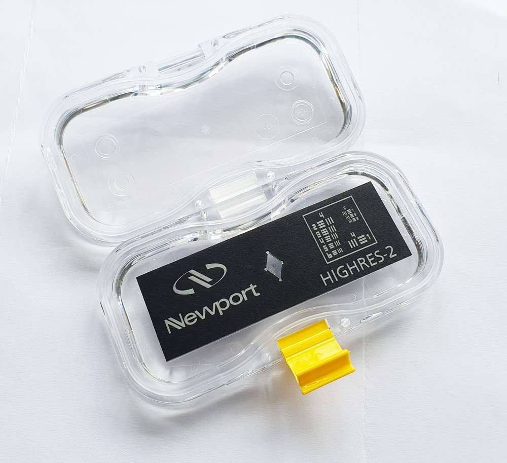
The pattern is chrome deposited onto a quartz substrate, which is mounted into the middle of a 3″ by 1″ aluminium slide as shown below. You can just about see the test pattern in the middle of the diamond shaped piece of quartz in the middle of the slide.
Newport Highres-2 test slide and holder
Overall it looks to be well made and with a good container which will hopefully keep it safe.
Back to the test pattern and resolution testing. The pattern is presented as a series of Groups from 4 to 11, with Group 4 having the largest lines, and Group 11 the smallest. Each group is further subdivided into 6 Elements, which again get smaller going from Element 1 to Element 6. The widths of the different lines are given on the Newport site – here.
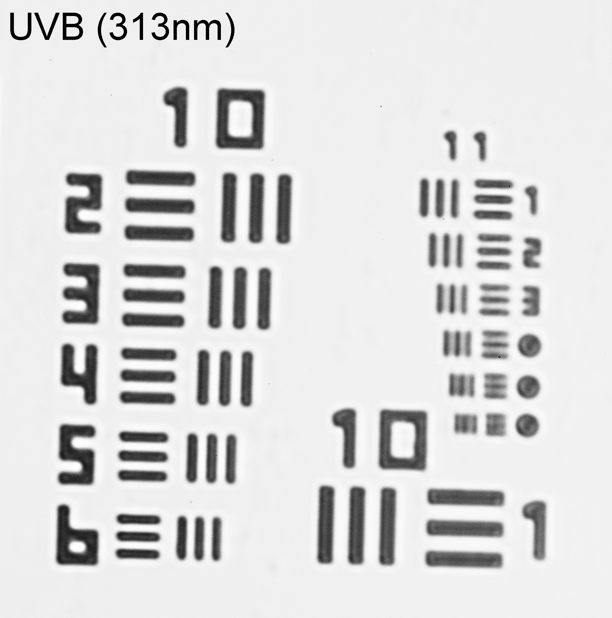
With using the Leitz 100x NA1.2 UV objective for imaging diatoms, it looked like I was seeing features down to about 200nm if not a little smaller, so the key parts of the test slide which were of interest to me were Groups 10 and 11 as these have the smallest features. Looking with 313nm gave the following image (cropped slightly just to show Groups 10 and 11). Images were taken using a monochrome converted Nikon d800 from MaxMax, which I can use down to 300nm. I also took the image as a Raw file and processed it in Monochrome2DNG to try and get a little bit more from it as the camera sensor has had the Bayer filter removed.
All Elements in Group 10 were clearer resolved using 313nm light. These lines go from 488nm down to 274nm wide. In Group 11, Elements 1, 2, 3 4 and 5 are clear to me, but Element 6 I’m just starting to struggle to break out the individual lines, although they can just be seen. In the image Group 11, Elements 4, 5 and 6 are identified by the dots instead of numbers. Keep in mind that Group 11, Element 6 has lines which are only 137nm across (Group 11 Element 5 is 154nm and Group 11 Element 4 is 173nm). So it does look as though that objective will certainly resolve features down to below 200nm and perhaps around 150nm. Put this into perspective – a single Covid-19 virus is about 100nm across. Not too shabby for a home built microscope.
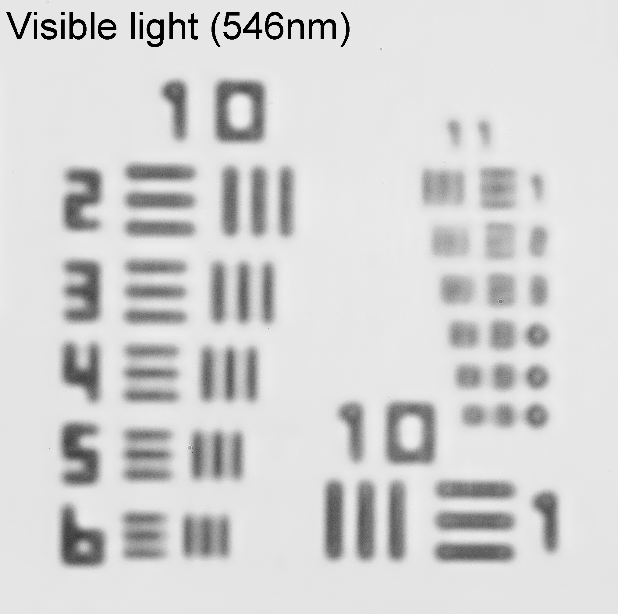
Just for comparison here are the images taken using 365nm and visible light (546nm) captured at the same time.
As expected, as the wavelength gets longer the resolution gets worse. Physics in action….. The quest for resolution was reason why microscopists started looking at UV transmission microscopy back in the early 1900’s. They used even shorter wavelengths of light – 254nm and 276nm – which makes me wonder how much more resolution I could get out of my microscope if I used these more extreme UV sources.
Imaging to produce nice photos is one thing, but there are times when we need to be able to put numbers against the things we image, to be able to quantify the things we are seeing. With the Newport Highres-2 resolution test slide, I have been able to do just that with my UV microscope and now have a way of being able to determine the resolution which can be achieved with different objectives and at different wavelengths.
Thanks for reading and if you’d like to know more about this or any other aspect of my work, I can be reached here.
Having the right tool for the job. It is important when doing measurements that we have access to the right techniques (and of course know how to use them – a fool with a tool is still a fool). When characterizing optical filters, I’ve normally just done transmission measurements. However with some filters they have dichroic coatings present on them which can reflect unwanted wavelengths of light even before the light passes through the filter. While I had tried doing some basic measurements of reflectance from these types of filters before, the results were never optimal. I recently decided to bite the bullet and order a proper reflectance probe so I could do this type of work in a more controlled manner. Today I’ll be sharing some initial data from it.
The probe I went for was one by Ocean Insight. They worked with me on the design which is always good when a company does that, and it arrived about 3 weeks after ordering it. I needed one which would work from the UV (250nm) to the IR (1100nm) to match the spectrometers and light source I have, and because those are the wavelengths which are most relevant for photography with normal cameras. I also needed it to be the right diameter for me to use on my Ocean Insight RTL-T stage. The incoming light illuminates the sample through 6 fibers arranged around a 7th one in the middle which is the one which goes to the spectrometer. I have an Ocean Insight FX spectrometer and an STS-NIR one as well, so can measure between 250nm and 1100nm by using the two devices.
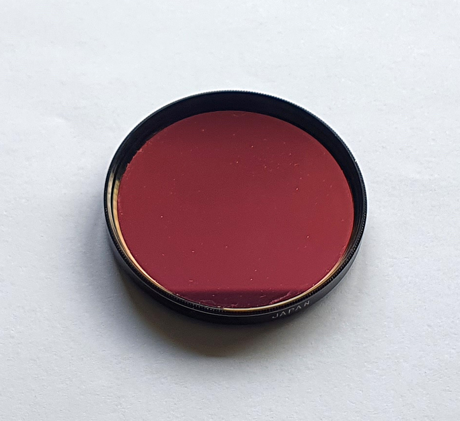
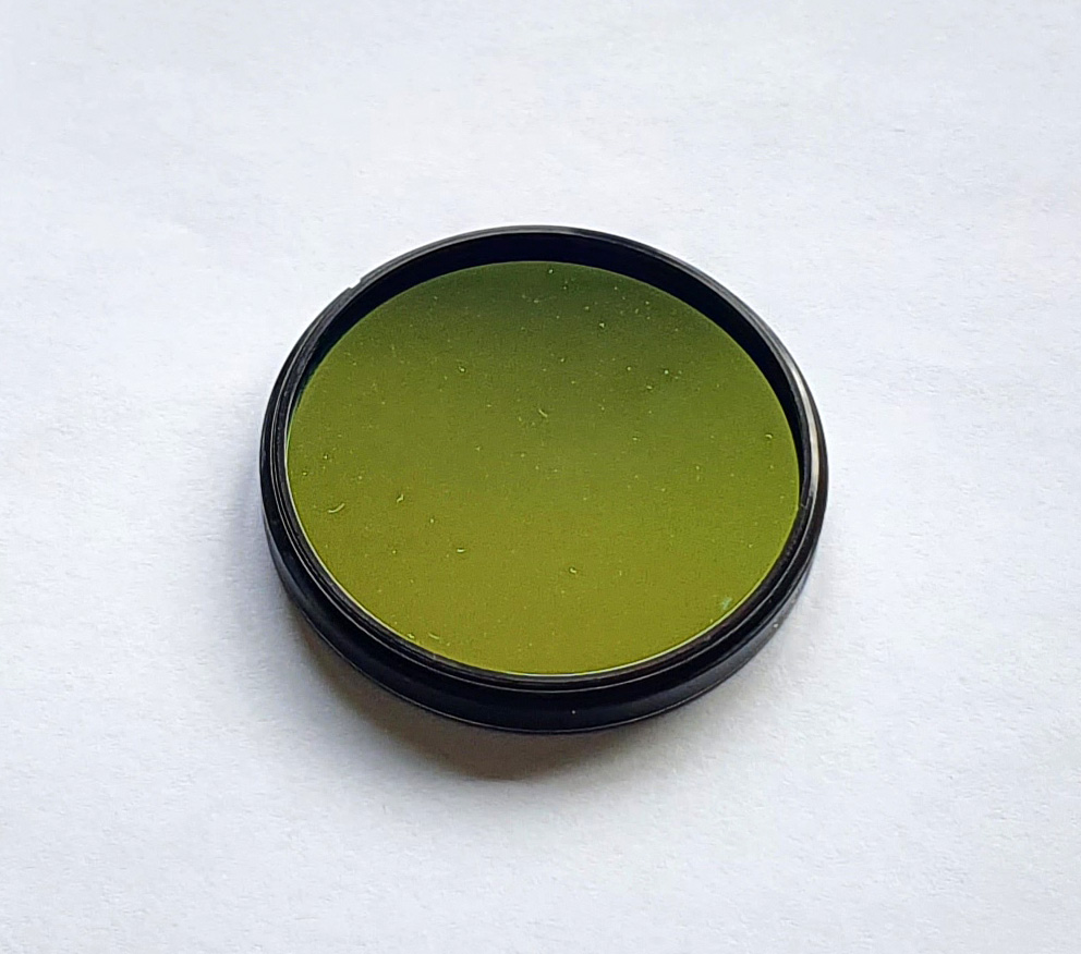
For a test filter I use a Baader U, which is a UV pass filter commonly used for UV photography. It has good blocking of unwanted wavelengths, and importantly for me, dichroic coatings on both surfaces which look different to each other. On mine one side is red/pink, and the other green/gold and I have remounted it in a 49mm filter thread for using on my camera lenses (see below).
Baader U filter – red/pink sideBaader U filter – green/gold side
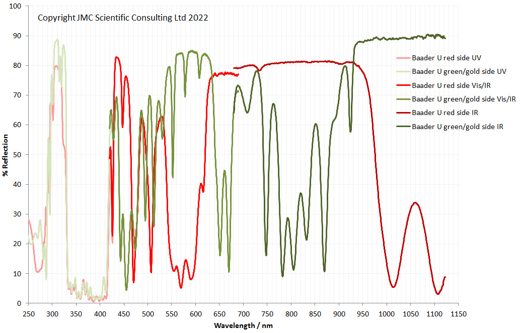
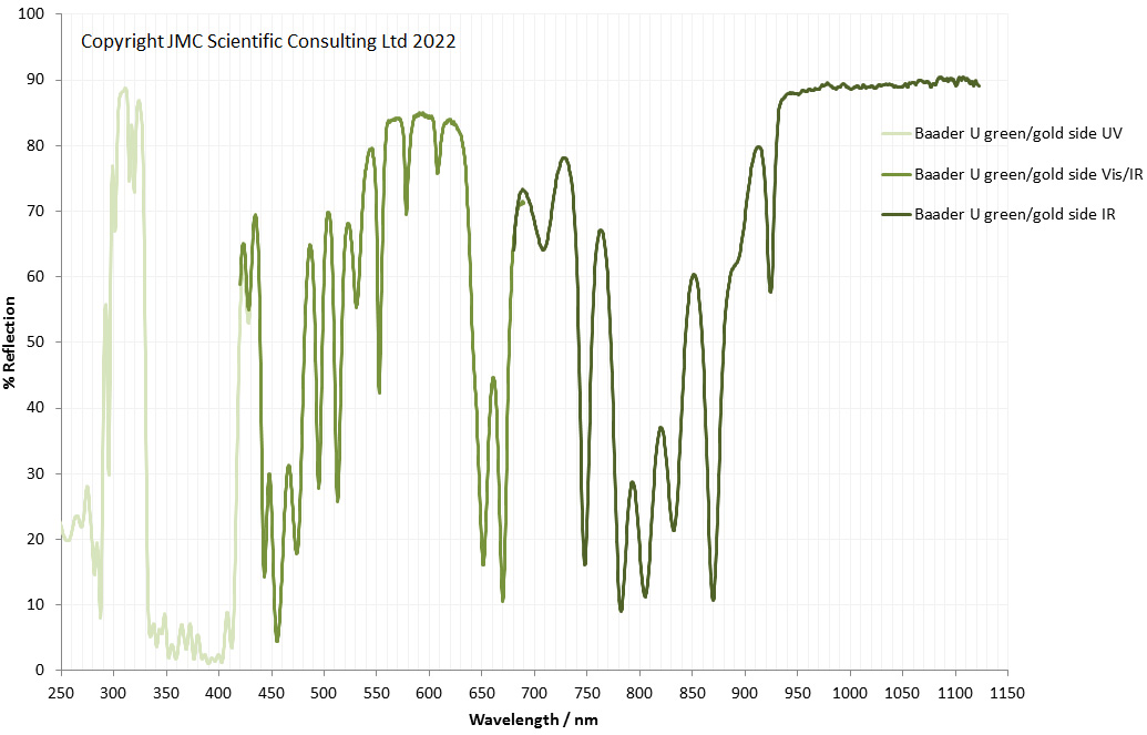
What do the filter coatings look like in terms of reflectance? Combining the measurements from both sides using both spectrometers gives the following rather complicated graph;
Full range of reflectance measurements from both sides of the Baader U filter
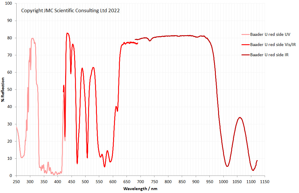
It’ll be clearer to show each side individually. First the red/pink side;
Reflectance from the red/pink side of the Baader U filter
And the same from the green/gold side;
Reflectance from the green/gold side of the Baader U filter
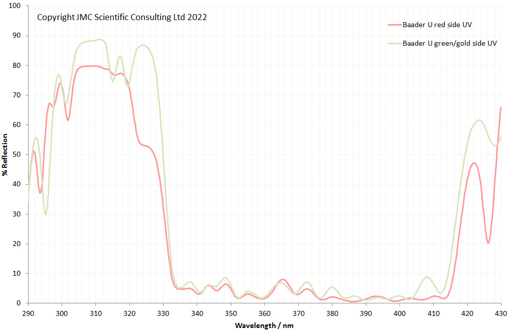
There are some big differences in terms of the reflectance from the two surfaces of the filter, especially in the red/IR region. The red side has the better blocking from 600nm to 1000nm, while the green/gold side has better blocking above 1000nm. It is common practise when using these filters for UV photography to reverse the filter compared to how it is normally supplied. This is because the mounting on a camera lens would naturally reverse it compared to mounting it on a telescope (one uses a female thread the other a male). In UV photography when using it in a camera and not a telescope it is recommended (by fellow UV photographers) to mount it with the red/pink side facing the subject. This makes sense as it presents the side which reflects the most red/IR before it can even enter the bulk interior of the filter.
The filter itself is used for UV photography, and has good transmission between about 330 and 400nm. The coatings on both sides are designed for this, as they both have very low reflectance in that region;
Baader U reflectance of both sides in the UV
I have deviated slightly from the normal approach for using this probe, and will explain why now. Normally when using this probe, Ocean Insight would recommend using a high reflectance specular reflection standard for calibrating the spectrometer before the measurement. However this does vary in reflectance across the wavelength range, and I could not justify the cost. Instead I bought two mirrors from Thorlabs – a UV enhanced aluminium one, and a protected silver one. I use the UV enhanced one for UV measurements and the protected silver one for visible and IR measurements. They offer very similar properties to the Ocean Insight specular reflectance standard and were about 20% of the cost. If I needed a NIST traceable standard I’d invest in a proper one, but for my work, these mirrors will be sufficient. It should be remembered though that the % reflection scores are vs the mirror, and that does vary slightly in reflectance at different wavelengths. This is one reason why full experimental details are needed whenever reporting data.
As always, thanks for reading, and if you’d like to know more about this or any other aspect of my work, you can reach me here.
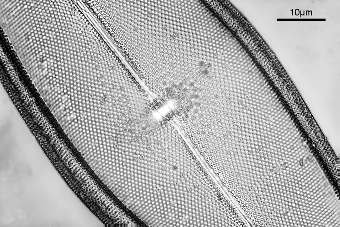
When it comes to testing equipment, I like to push it and see what it is capable of, trying to find the limits of what it can do. So I come to the latest diatom image taken on my UV transmission microscope. This one was imaged using 313nm light, and using a Leitz 100x NA 1.20 glycerine immersion objective (mentioned previously here).
Diatom imaged at 313nm using a Leitz 100x NA 1.2 UV objective
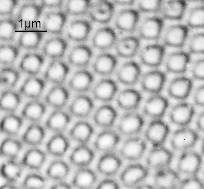
The image above was of the central part of a diatom and has been reduced in resolution for sharing as the original (taken with my monochrome converted Nikon d800 from MaxMax) was 7360×4912 pixels. Going closer into part of the original image gave the following.
Crop from the original diatom image at 313nm
The ’round’ features are about 500nm across and the gaps between them are about 200nm wide. For a home built microscope, I’m very happy with the resolution, and it seems to be approaching the limit predicted by Abbe (using 313nm light and a NA 1.20 objective, the theoretical resolution should be about 130nm). Keep in mind here that every aspect of the imaging setup needs to be optimized to get the best image. The condenser I used was only NA 0.85, while the objective was NA 1.20. This will reduce the maximum obtainable resolution. At these types of extreme magnifications, every little thing matters. Is there more resolution to be had from this setup? Maybe, but I think not, at least not without going to even shorter wavelengths. The microscope should be usable down to around 250nm, but the camera, light source and filters would all need to be changed for that so at the moment it is not a viable option.
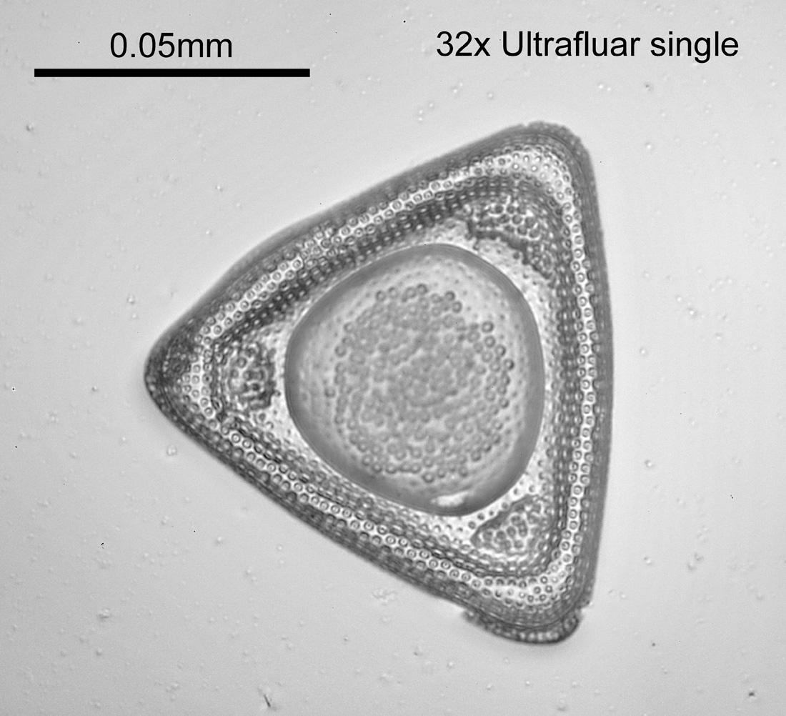
Here is a lower magnification image showing the whole diatom (taken at 313nm with a Zeiss 32x Ultrafluar).
Diatom taken with 32x Zeiss Ultrafluar objective
Thanks for reading, and if you’d like to know more about this or any other aspect of my work, you can reach me here.
Testing, testing, testing. As always with new equipment and methods it is helpful to test them to see what they are capable of and where their limitations are. With my UV microscope, I recently had a test slide made using quartz components and which had a variety of diatoms mounted on it. These diatoms have very small features (often sub micron in size) and are great for testing optical setups. Also, being made from quartz it is usable in the UV where glass would block the light.
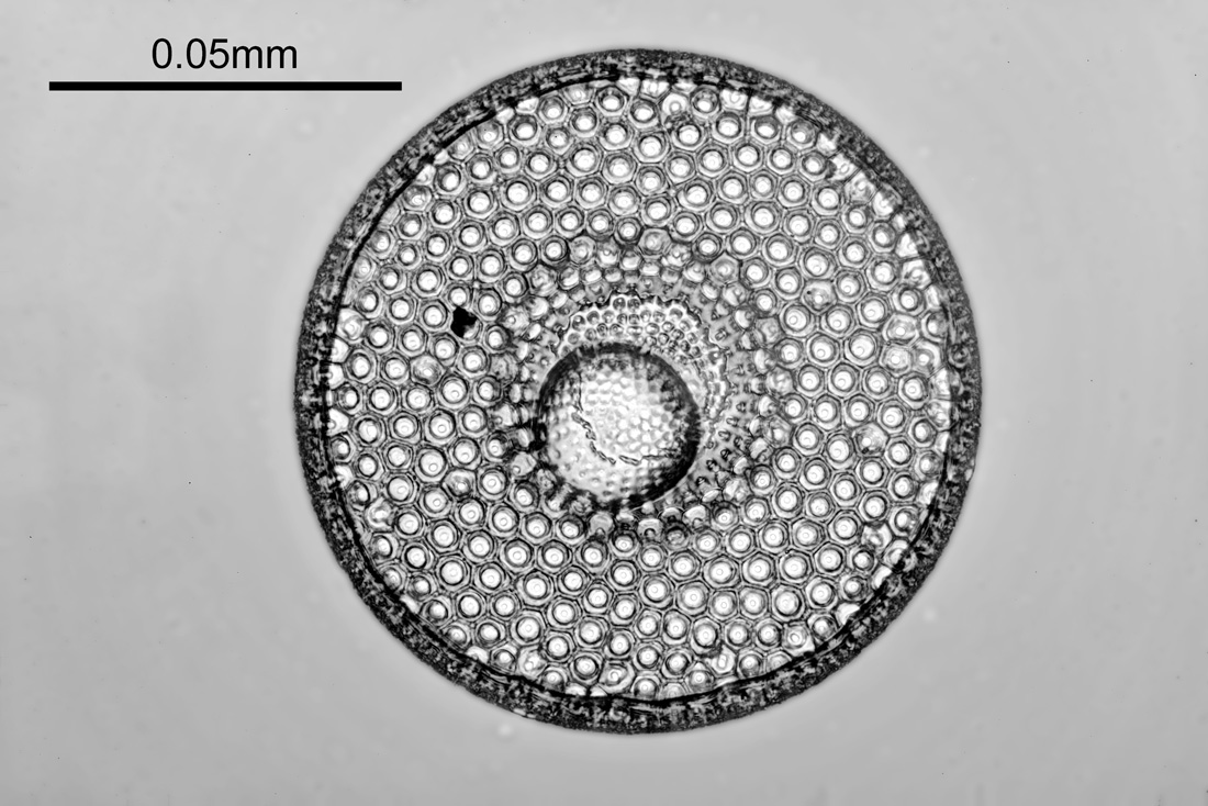
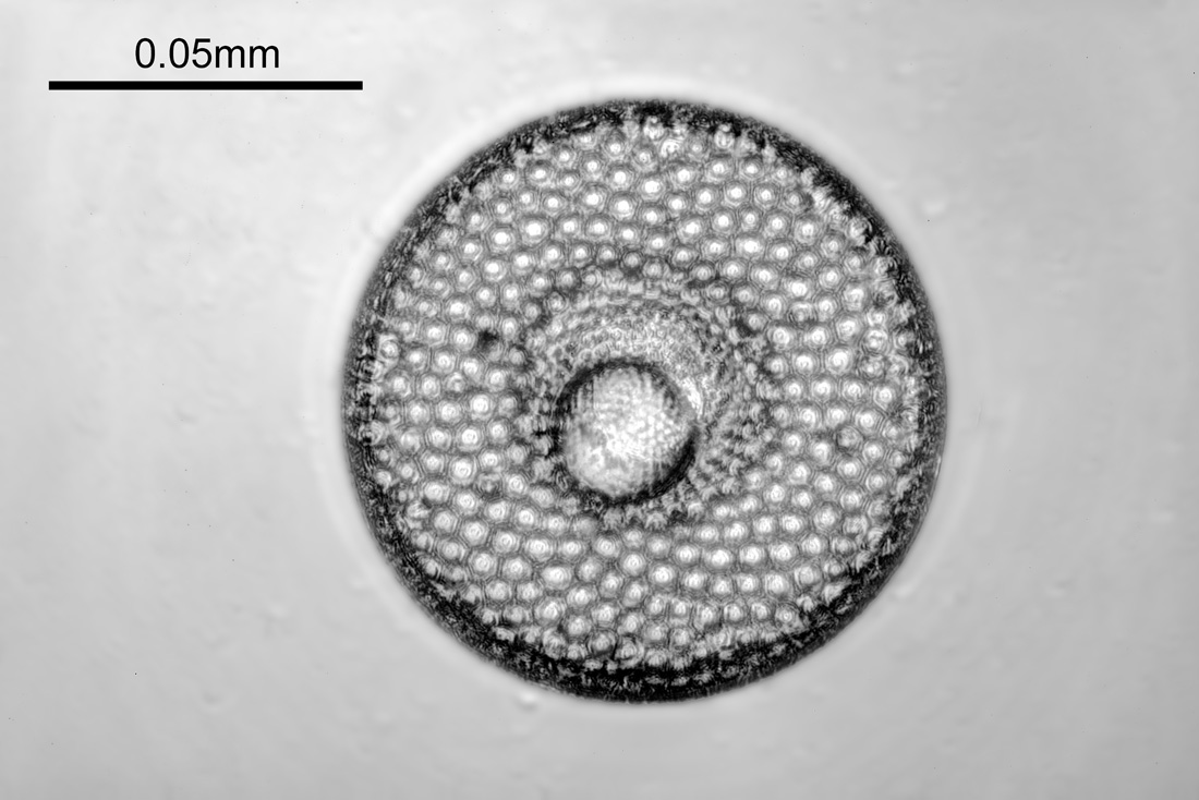
Todays images were done with 3 different objectives – but before we get into the specifics of the objectives, I’m going to share one of the images produced, because, it is pretty special. This was made with the Leitz 40x NA 0.65 objective which will be discussed below and is a 313nm brightfield transmission image.
Leitz 40x NA 0.65 objective image at 313nm
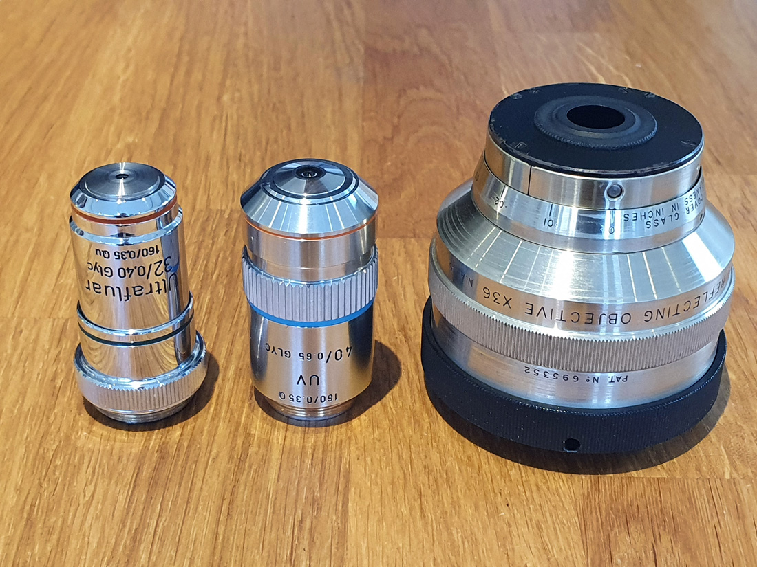
Back to the objectives. Three were used for this – a Zeiss 32x NA 0.4 Ultrafluar, a Leitz 40x NA 0.65 UV objective, and a 36x NA 0.5 Beck reflecting objective, all of which are shown below.
Left to right – 32x Zeiss Ultrafluar, 40x Leitz UV, and 36x Beck reflecting objective
I normally use the Ultrafluar when I need an objective in this sort of magnification range, but wanted to check the other two out. The Zeiss and Leitz were both used with glycerine immersion fluid, and the Beck was used dry. The Beck is very different to the other two being a mirror lens, and I checked the alignment of it before using it. The diatom was imaged at 313nm, and each image is a stack of about 13 images made in Zerene stacker. Some processing of the final images was done in Photoshop, but all images were treated similarly. They have been reduced in size for sharing online.
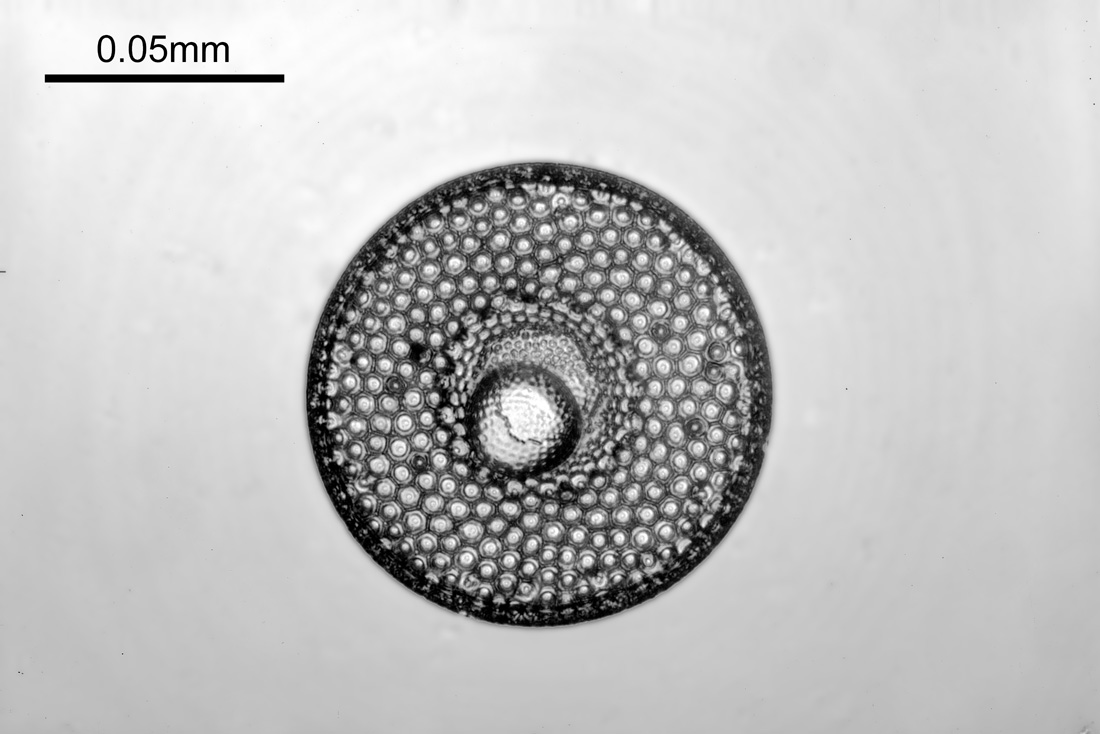
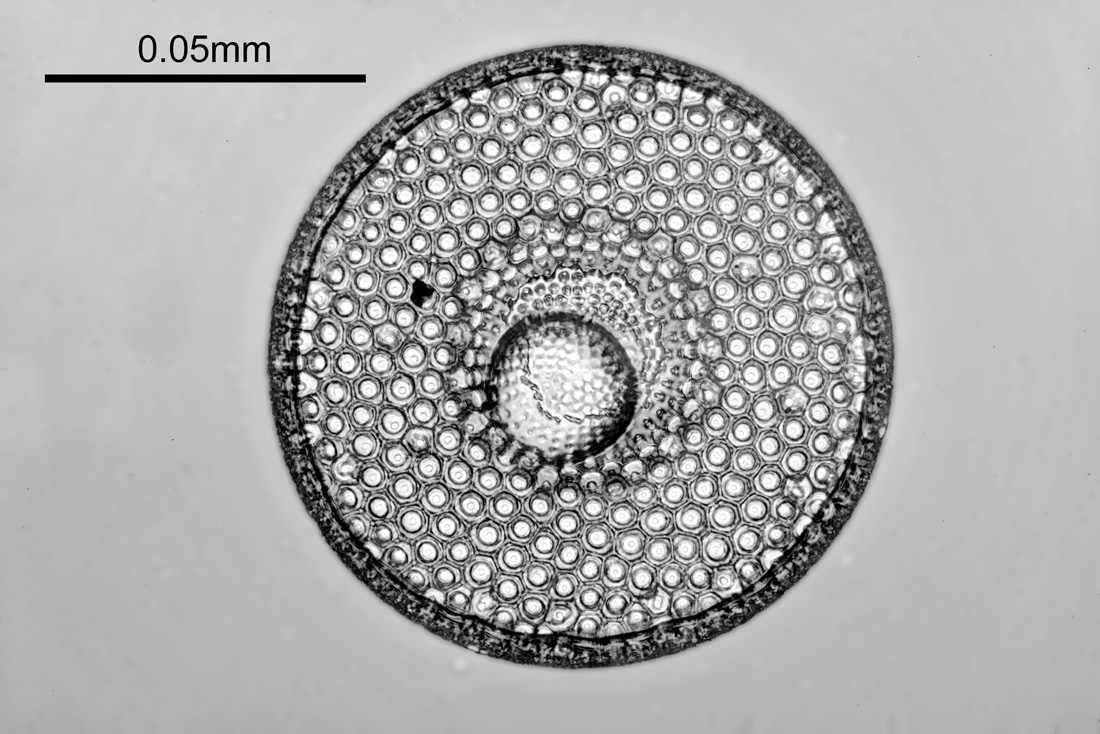
First the 32x Ultrafluar.
Diatom image at 313nm with the 32x NA 0.4 Zeiss Ultrafluar
Next with the 36x Beck reflecting objective.
Diatom image at 313nm with the 36x NA 0.5 Beck reflecting objective
And finally with the 40x NA 0.65 Leitz UV objective.
Diatom image at 313nm with the 40x NA 0.65 Leitz UV objective
Obviously the field of view is different with the three objectives as their magnifications are not the same. The 32x Ultrafluar image is certainly very good, especially for a NA 0.4 objective. The 36x Beck reflecting objective image is lower contrast and not as sharp, but still shows a lot of detail. However the star of the show here was the Leitz 40x NA 0.65. The final image it produced was extremely sharp and full of detail.
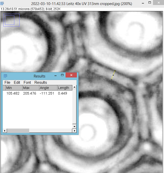
Not much is known about the Leitz 40x UV objective, certainly nowhere near as much as about the Ultrafluar objectives, however I have written a bit about it here. To try and get a bit more detail on the resolution it was producing I did a crop of the original image in ImageJ and took some measurements. The area assessed is shown below.
Assessment of cropped image from the Leitz 40x NA 0.65 objective
The yellow line in the image above is 449nm long, so it looks like this objective is easily resolving features below 0.5micron in size. Abbe’s resolution equation says that this objective should have a resolution of 241nm when used with 313nm light, and from the looks of this image it probably isn’t far off that. Makes me wonder what my Leitz 100x NA 1.20 objective is capable of, but that will have to wait for another day….
I’m certainly no diatom expert, but they are beautiful structures and make for great photos, so I will be doing more in the future. It’s been great to finally be able to test some of my UV objectives with samples like this, and to be able to produce some real life images with these historic optical pieces. Thanks for reading, and if you’d like to know more about this or any other aspect of my work, I can be reached here.
Time for a bit of historical microscopy today. I’ve previously written about the Zeiss Monochromat objectives – quartz objectives originally produced in the early 1900s and designed to be used at 257nm or 275nm (see here). Now the microscope is up and running for UV work, I thought I would try out one of these historical pieces and see what type of image it can produce.
The objective of choice was a 6mm NA 0.35 Zeiss Monochromat designed for 160mm tube length and for imaging using 275nm light from a Cadmium arc source. The objective is shown below.
6mm NA 0.35 Zeiss monochromat objective
This objective is made from quartz lens elements and has an RMS thread for mounting it. It is also designed for 160mm tube length microscopes which means it is ideal for use on my modified Olympus BHB. Here it is mounted up and in use for imaging a diatom slide.
What about the image quality? To test this I did a single picture of a diatom at 313nm with it and compared it with an image produced by a 32x NA 0.4 Zeiss Ultrafluar which is what I use for my UV imaging research. Firstly with with the 6mm NA 0.35 Zeiss Monochromat.
Diatom image at 313nm with 6mm NA 0.35 Zeiss Monochromat objective
And now a comparison shot with the 32x NA 0.4 Zeiss Ultrafluar at 313nm.
Diatom image at 313nm with 32x NA 0.4 Zeiss Ultrafluar objective
The 6mm Monochromat had almost exactly the same field of view as the 32x objective. It produced a usable image at 313nm, although was not as sharp as the Ultrafluar. This is not a huge surprise – the Monochromat has only quartz elements (the Ultrafluar is quartz and calcium fluoride), it has a slightly lower NA, and is also being used at a wavelength that it wasn’t designed for. It is also a much older design and construction. The Monochromat also had a huge focus shift compare to visible light which the Ultrafluar does not. Again, this is not unexpected, but must have made working with it in the days of film challenging to say the least.
Overall, it was amazing to use such a historical piece in the manner in which it was originally designed for (bearing in mind the wavelength used wasn’t what it is specified for). Over 100 years later and it is still capable of producing images. Thanks for reading, and if you’d like to know more about this or any other aspects of my work, I can be reached here.