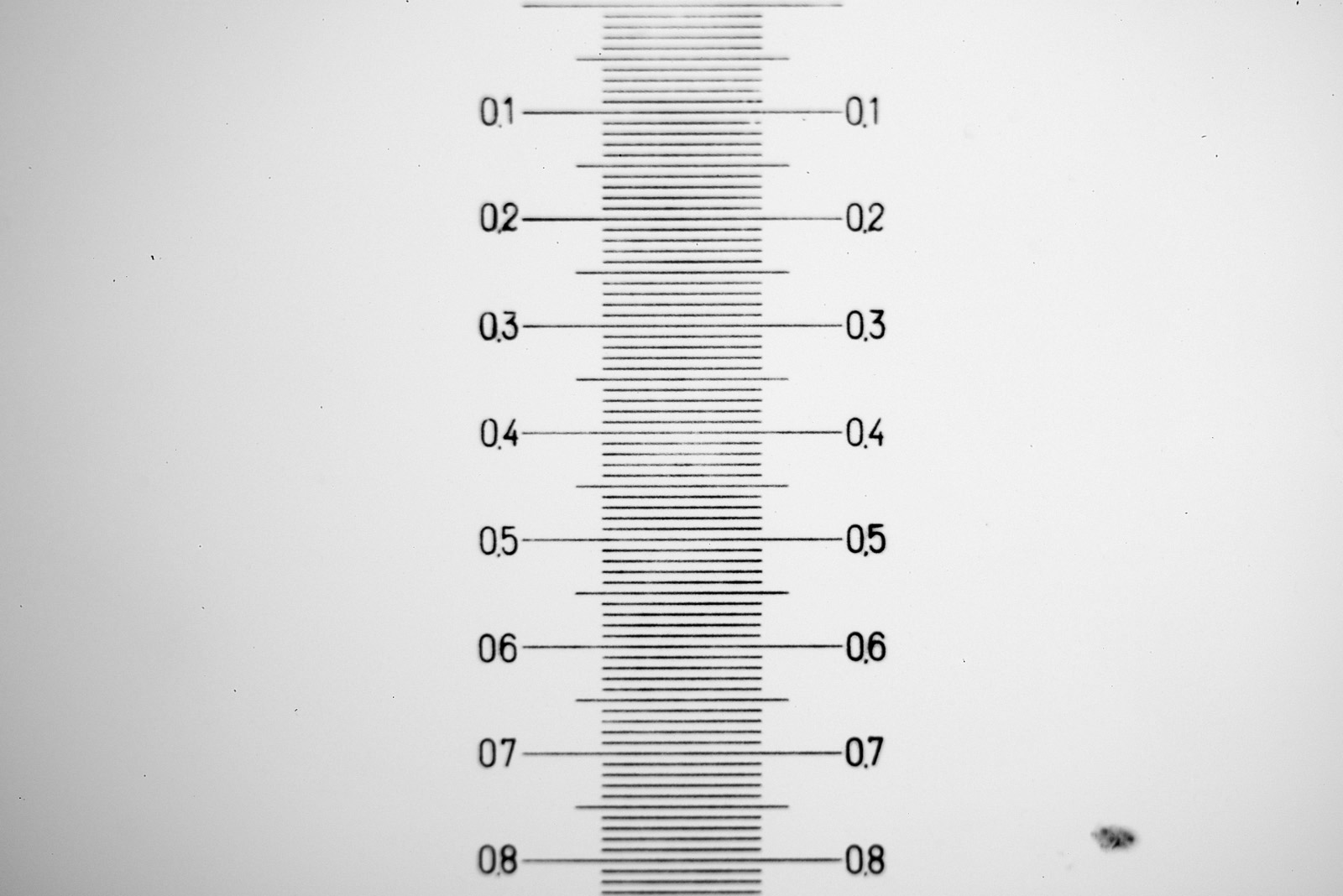
With microscopy it is important to know how big the object is that you are imaging. The simplest way to do this is to use a stage micrometer (also called a graticle or graticule). These are small rulers and designed to be imaged using the same optics setup as being used to image the subject. The ‘pixels per micron’ can then be calculated and used to make a scale bar on the image of the subject. Today I’ll show you a couple of the ones I use. But first a nice image from an old Leitz one showing their name as well as 250µm of the micrometer.
Antique Leitz stage micrometer
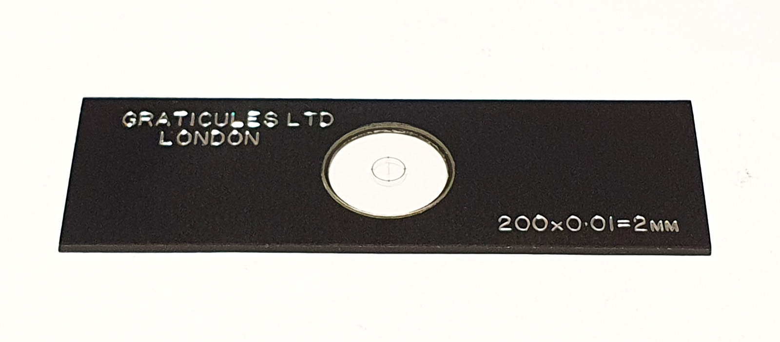
The ones I tend to use on a daily basis were made by Graticules Ltd in the UK (now know as Graticules Optics Ltd). I have a 2mm one with 10µm divisions) and a smaller one which has 2µm intervals which I use for for higher magnification objectives. Both of these were bought second hand from ebay for about £30 to £40. Here’s what the 2mm one with 10µm divisions looks like.
2mm Graticules Ltd stage micrometer
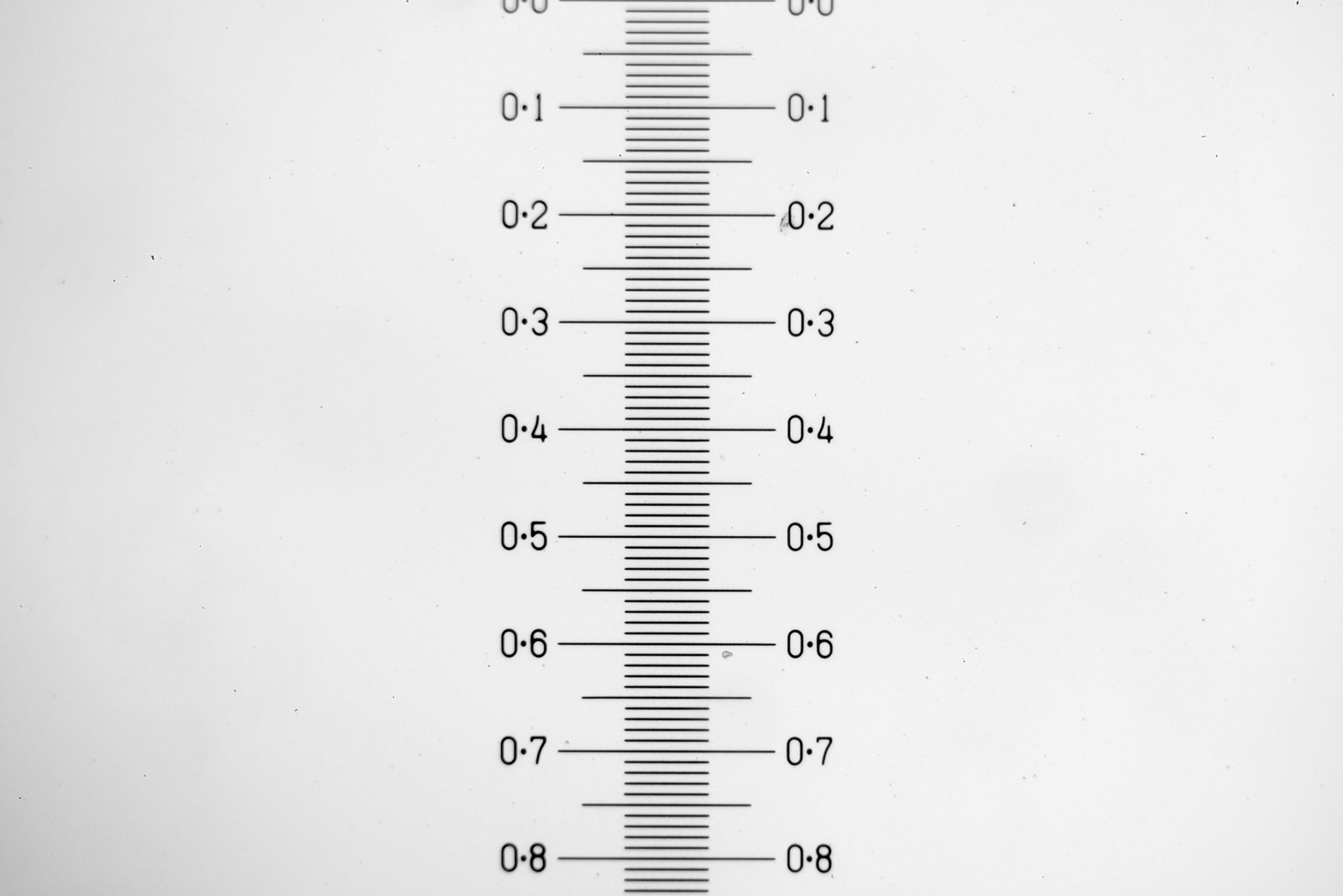
Using a 10x Olypus UVFL objective this is what the scale bar from the Graticules Ltd slide looks like.
Image from the Graticules Ltd slide using a 10x objective
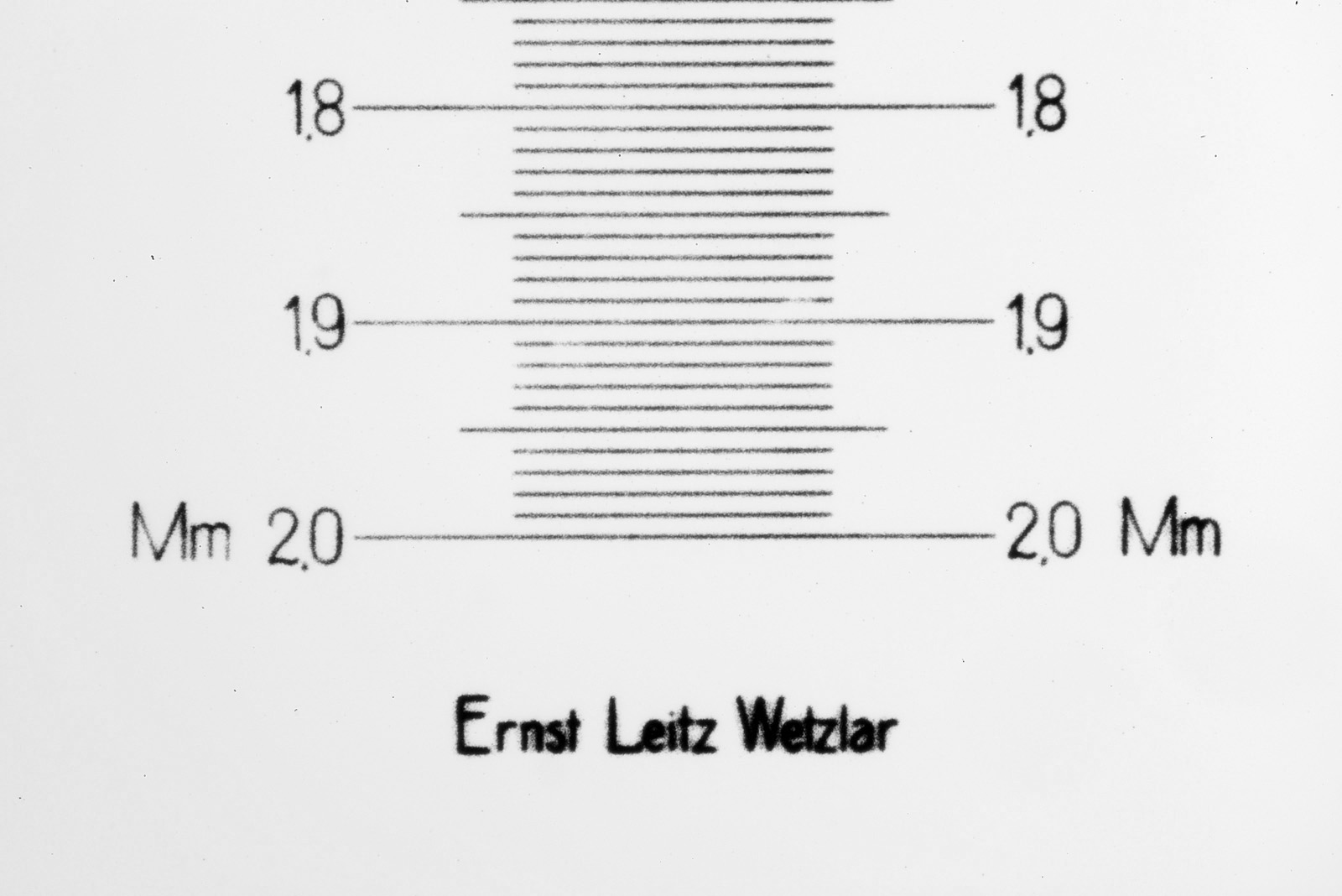
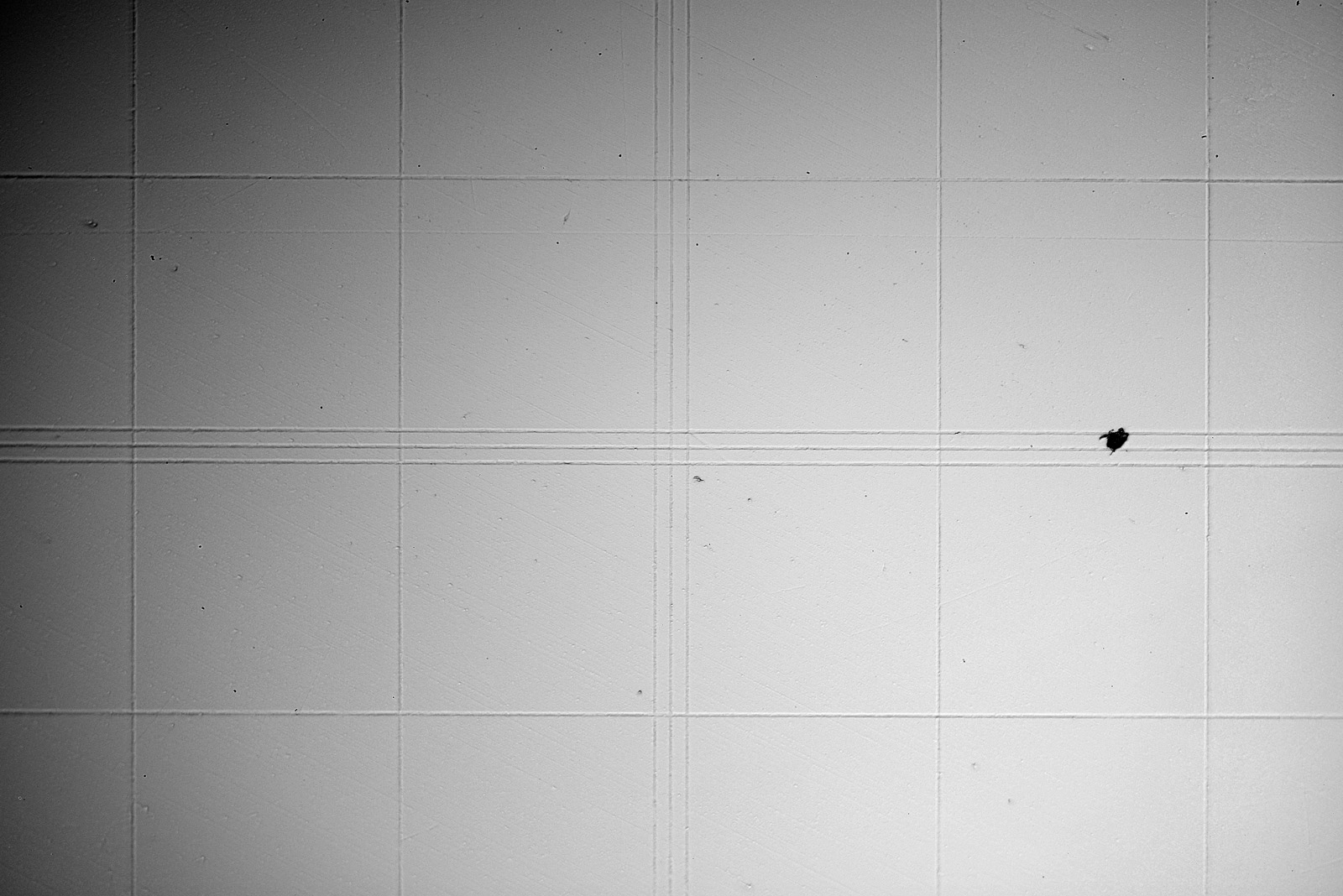
In the image above, each larger division is 0.1mm (100µm) with 10µm smaller divisions between the larger ones. I also picked up an antique Leitz one, which is also 2mm long and has 10µm intervals. Here’s what that slide looks like.
Antique Leitz stage micrometer
Interestingly the Leitz one has a coverslip attached which the Graticules Ltd one does not. Here is an image of the micrometer scale on the Leitz slide using the same setup as for the Graticules Ltd slide above.
Image from the antique Leitz slide using a 10x objective
As can be seen from the images of the micrometer, both slides are giving the same scale – about 830µm from the top of the image to the bottom. The Leitz one also has the makes name on it below the scale as shown in the first image in this post.
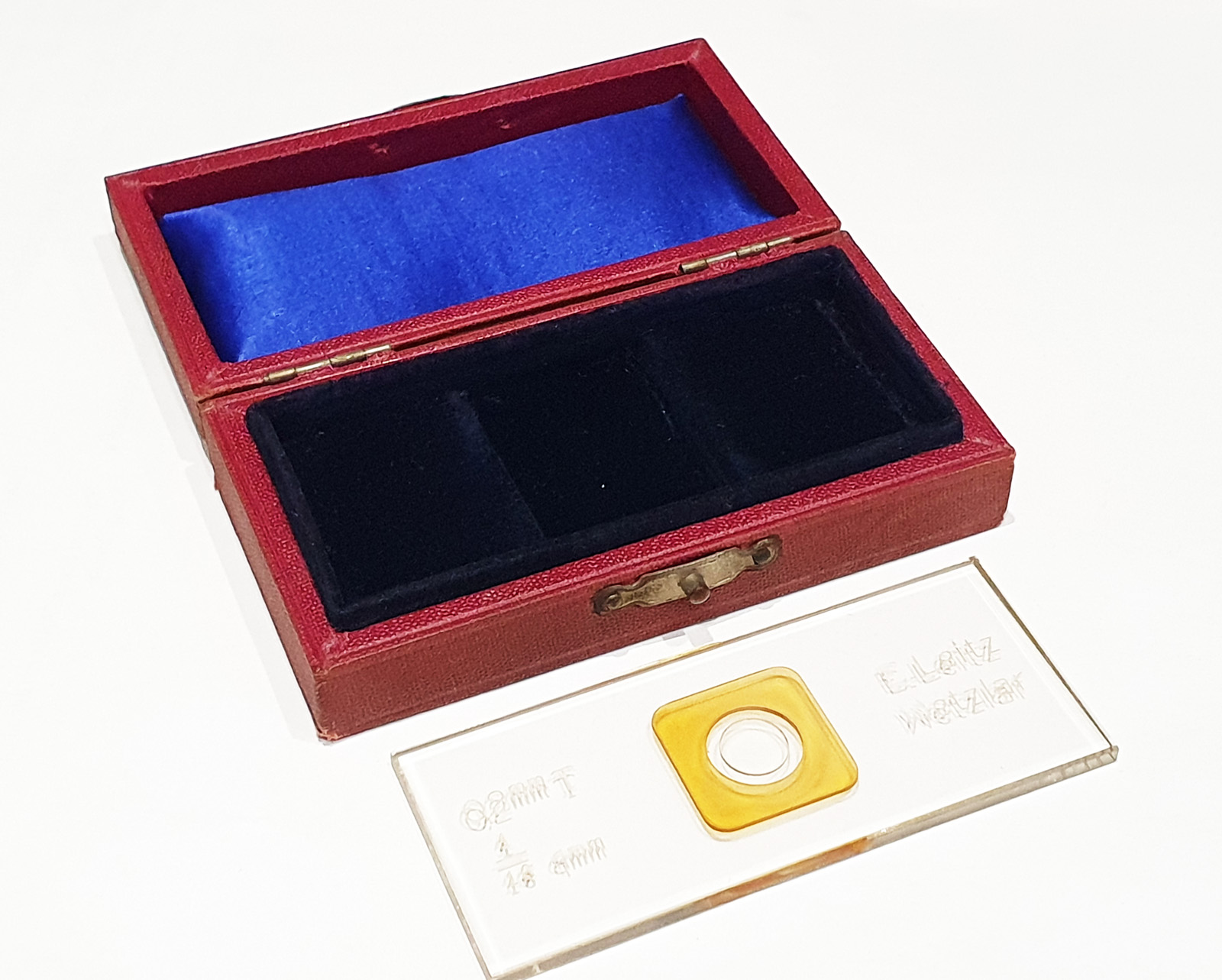
I also bought another Leitz one which I thought was a micrometer, see below.
Leitz haemocytometer slide
Turns out this wasn’t a stage micrometer at all, it was actually a haemocytometer, used for counting cells (you can read more about them here). Here’s an image from the slide.
Close up of the rulings on the Leitz Haemocytometer slide
I should also point out that there are plenty of new, cheap, stage micrometers available from places like ebay, however I have no idea how accurately made they are, which is why I tend to look out for older, second hand ones. In addition to these types of glass ones, they are also available on metal or opaque substrates for reflection microscopy.
The measurement side of things tends to often go unnoticed when compared with some of the beautiful subjects which can be imaged, but it is an important aspect of microscopy. As always, thanks for reading, and if you’d like to know more about my work I can be reached here.
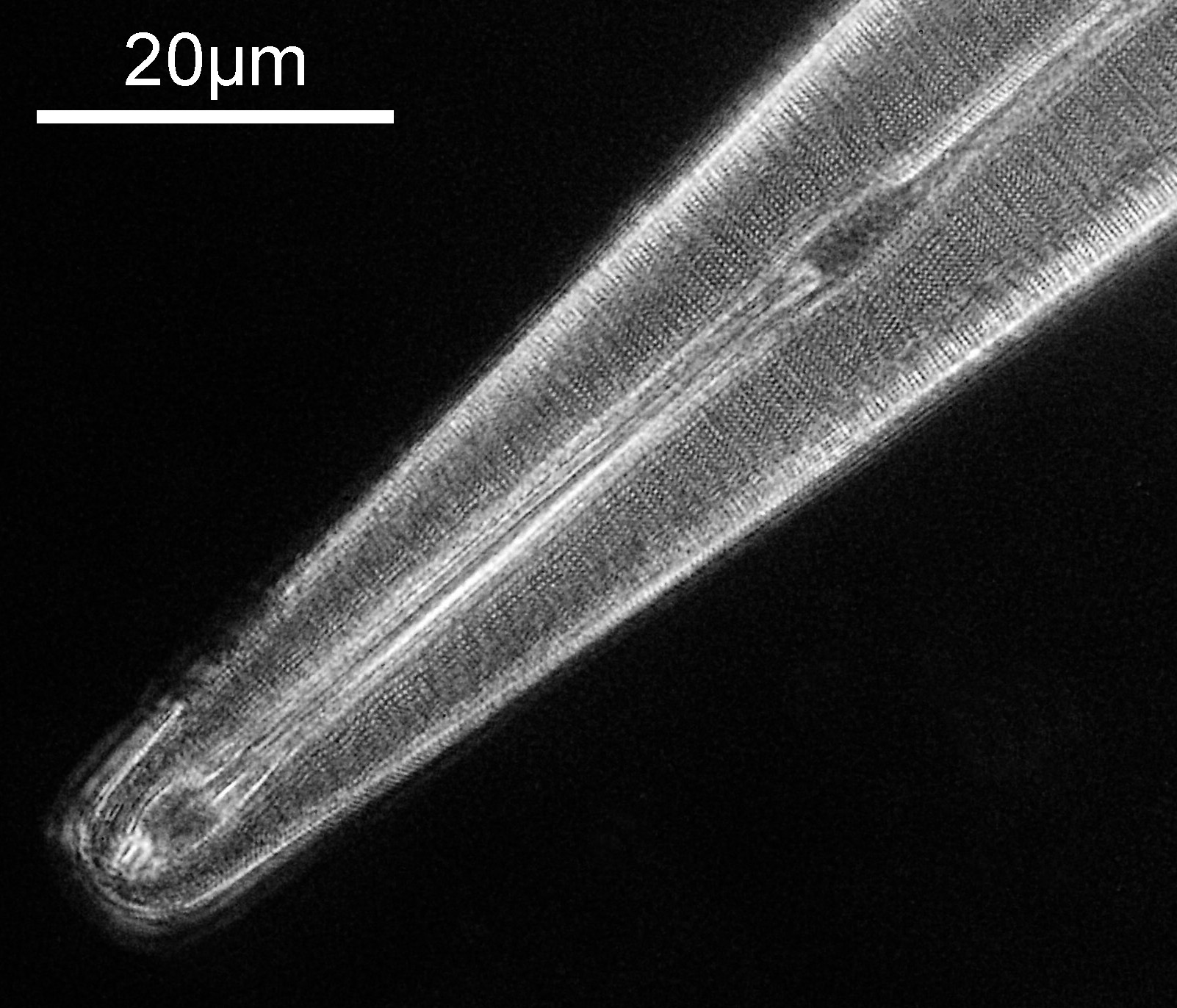
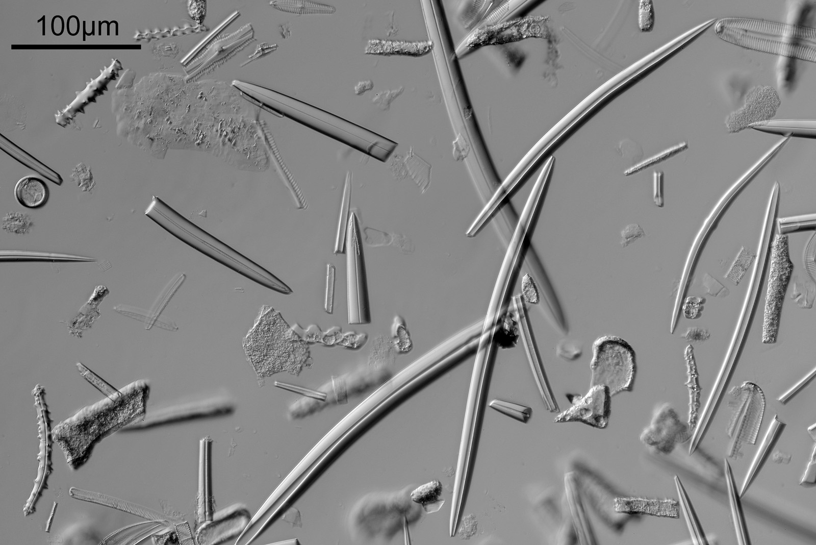
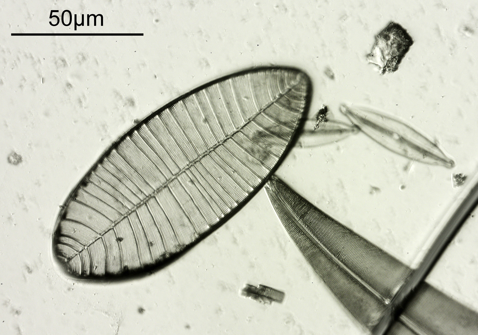
A short update today. I returned a diatom slide I have imaged before – the Amphipleura linheimerii slide originally imaged here. I wanted to try imaging it at 365nm, but using a Watson Quartz cassegrain condenser that I have on loan (a very special condenser, which I will try and write more about in the future). In summary, the condenser is a high NA dark field condenser, and being made from quartz has great UV transmission. This post shares an image from the slide using 365nm dark field illumination.
First though a quick note about the setup. Microscope was my UV modified Olympus BHB. Light source was a 365nm torch slid into the light port of the microscope. Condenser was a Watson quartz cassegrain one, which was used with glycerine/water as the immersion fluid. The objective was an Olympus 40x NA 1.3 silicone immersion lens, which I used with glycerine/water as the immersion fluid. Photoeyepiece was an Olympus 2.5 NFK. Then I used 2 stacked Edmund Optics 365nm, 10nm FWHM bandpass filters. Finally a monochrome converted Nikon d800 which is UV sensitive.
Ok, the image – this has been cropped slightly, and has been reduced in resolution for sharing.
Amphipleura lindeimerii dark field image
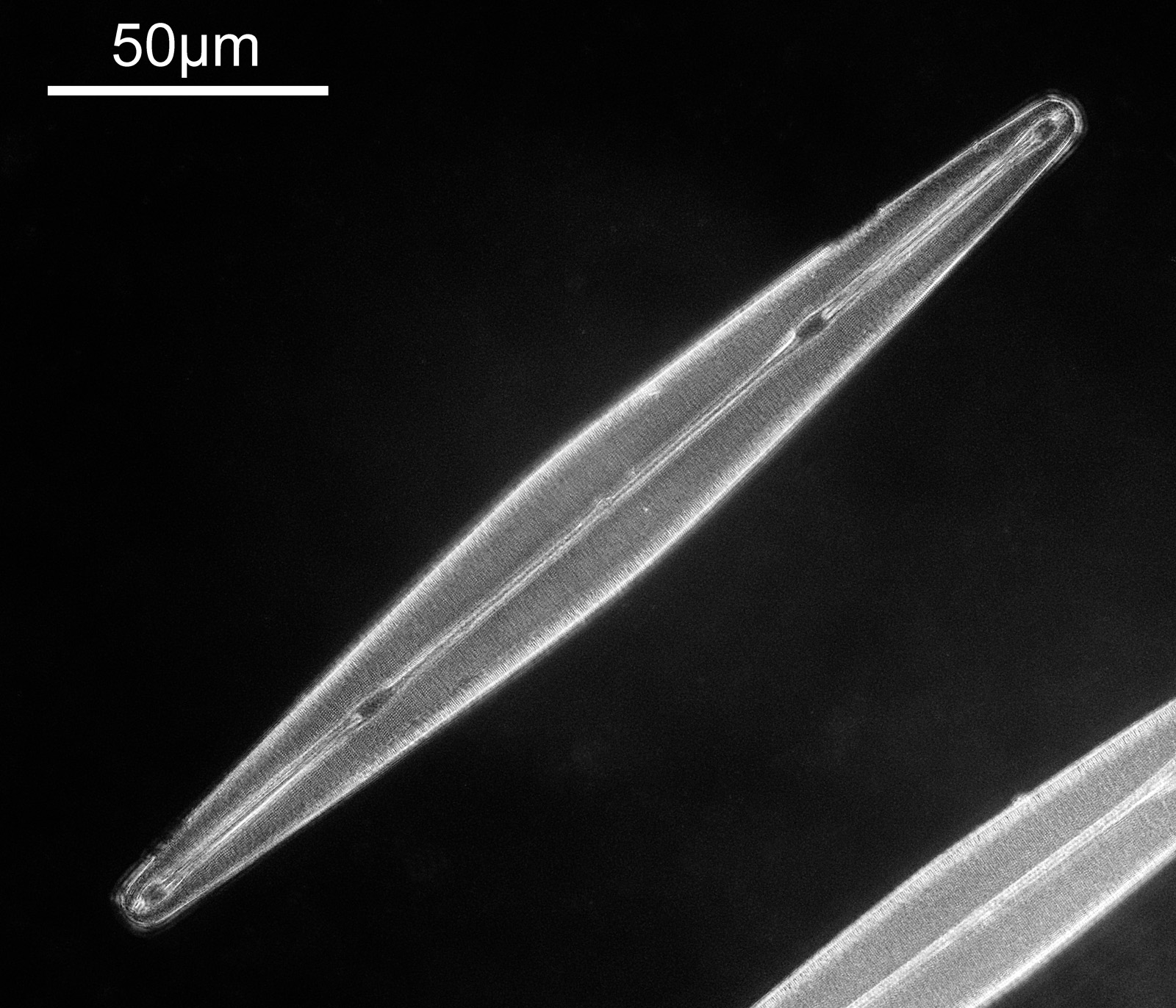
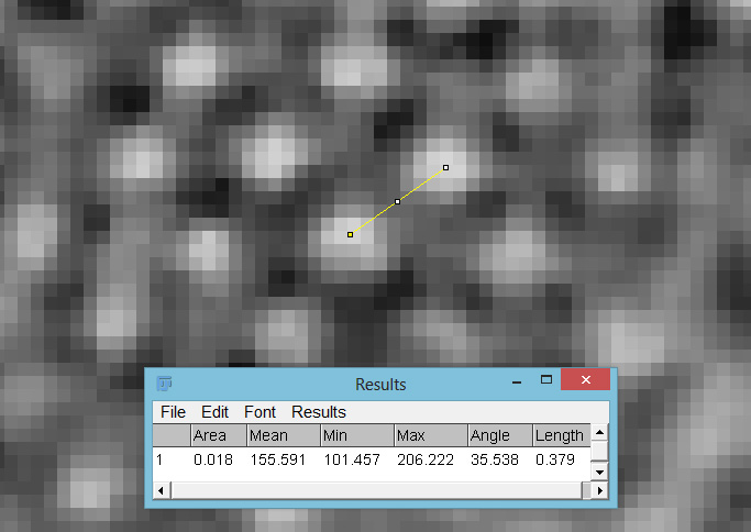
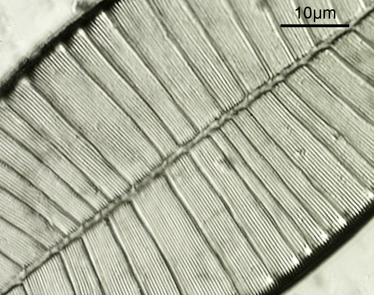
There are two examples of the diatom on the slide, and part of the other one can be seen in the lower left of the image above. There is plenty of detail in the image, but perhaps that does not show up as well with the lower resolution image being shared here. Here’s a crop, at original pixel resolution.
Amphipleura lindeimerii dark field image crop
With the cropped image some of the smaller features of the diatom now become visible. The distance between the small white dots was measured on using ImageJ was was found to be about 380nm (length 0.379 in the image below, as it was calibrated in microns).
Distance between the centres of the white dots in the image
A few things to note with this setup. Glycerine/water was used as the immersion fluid, while the objective was designed for silicone. Glycerine/water was used for a few reasons – firstly, I had some, secondly, it is a similar refractive index to the silicone, and finally it is much, much easier to clean. However I have to acknowledge this may impact performance of the objective. Being quite a low magnification objective, the field of view was large. As such the resolution achievable by the objective is getting close to the actual pixel resolution of the camera. I did try taking RAW files and then converting them to monochrome in Monochrome2DNG to get more resolution, and I even tried frame averaging in the camera, but neither of these improved things noticeably and I just stuck with the original single frame jpg captured in the camera in the end. The slide itself was not very UV transparent. I suspect if I measure the transmission spectrum of the slide, it will not be great at 365nm. As such this was not the ideal subject. I am also not sure I got the iris on the objective fully optimized, so perhaps a little more resolution can be squeezed from this setup.
Diatom imaging in the UV continues to be a fascinating journey, and one i will continue to pursue. As always, thanks for reading, and if you’d like to know more about my work, I can be reached here.
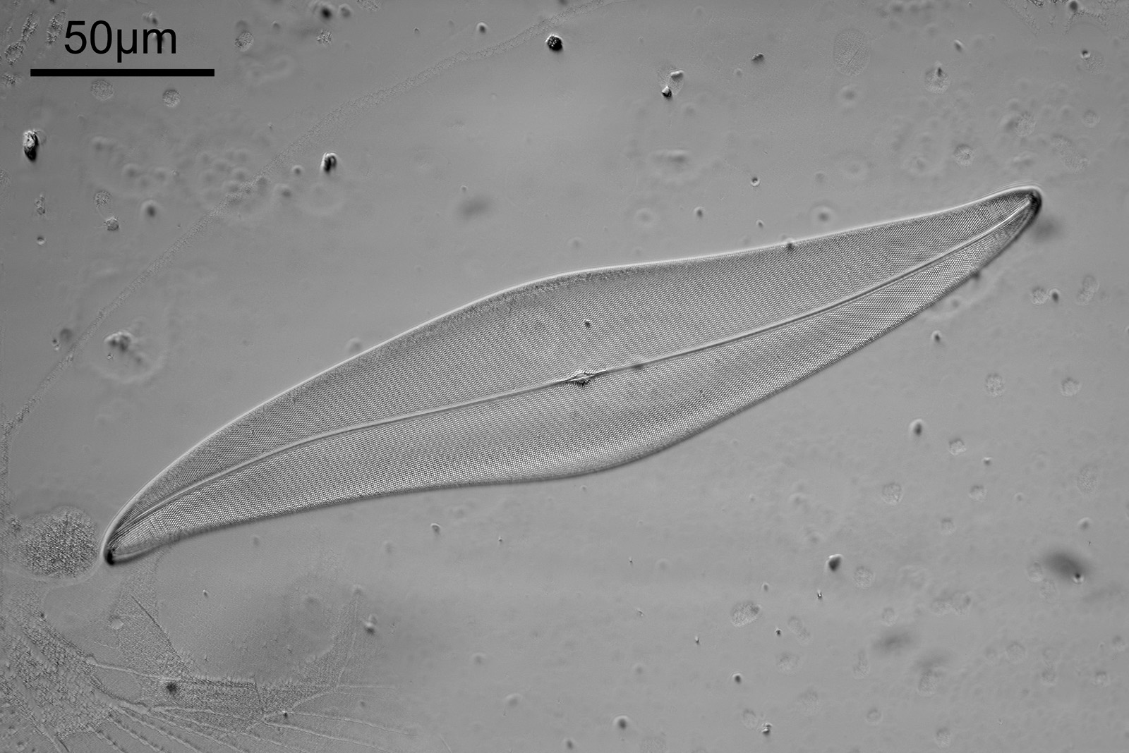
With my UV microscopy, I’ve noticed a dramatic improvement in resolution as the wavelength decreases. A well known effect, but the UV gives a great demo of how big a change can be observed – for example see my work on a test slide here. However converting a microscope to be able to image in the short wavelength UV region is no small task as glass absorbs the light. Is there a benefit to filtering visible light to image in the short wavelength blue region? There certainly is, and again this is well known, and is something I regularly do. However I thought I would share an example to show the effect, and also how to go about doing it in practice.
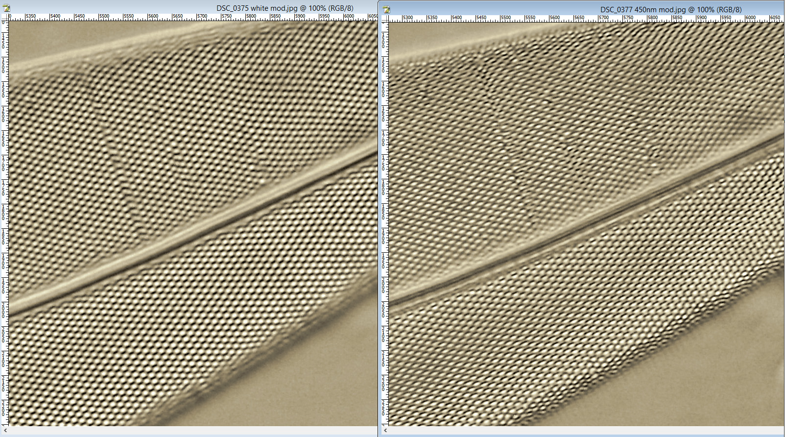
The test slide was a piperine mounted diatom slide, and the subject a Pleurosigma angulatum that was present on it. I set up my Olympus BHB with a 40x Olympus Dplan Apo UV objective (set the coverslip thickness collar to as thick as it would go, as the sample had a thick coverslip, and this gave the best setting). Camera was a monochrome converted Nikon D800. Light source a white light LED (more on that later). Condenser an Olympus Aplanat Achromat, set to oblique. Single image, no stacking. Everything was kept the same for the images, except a Thorlabs 450nm (40nm FWHM) filter was added above the photoeyepiece for the 450nm image. Images from the white light and the filtered 450nm light were processed the same way, and the full images have been reduced for sharing here.
First the white light image.
White light image
Next, the 450nm light image.
450nm light image
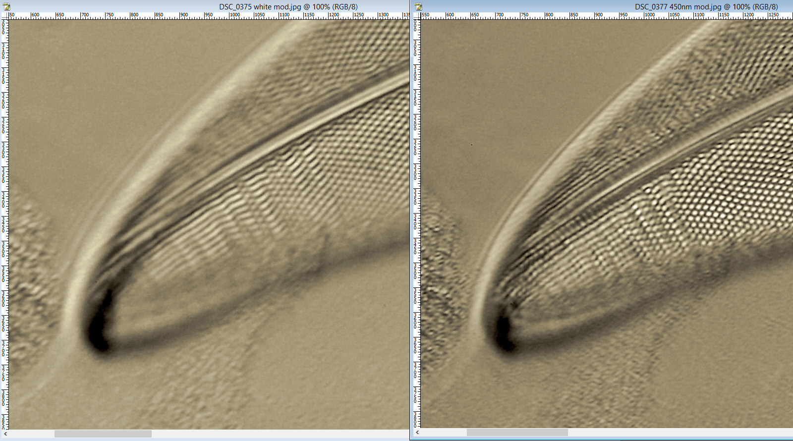
At first glance there doesn’t look to be much between the two images, however going in closer on parts of the images tells a different story. Here are a couple of sets of crops from different parts of the diatom. In each crop the white light image is on the left, and the 450nm image on the right.
Magnified and cropped portions of the diatom. White light on the left and 450nm light on the right.Magnified and cropped portions of the diatom. White light on the left and 450nm light on the right.
Note, the crops above were taken as screen grabs, and have a slight warm tinge to them as that is how I like my monitor. It is subtle, but there is a slight improvement in resolution as a result of using 450nm light vs the full spectrum of the white light.
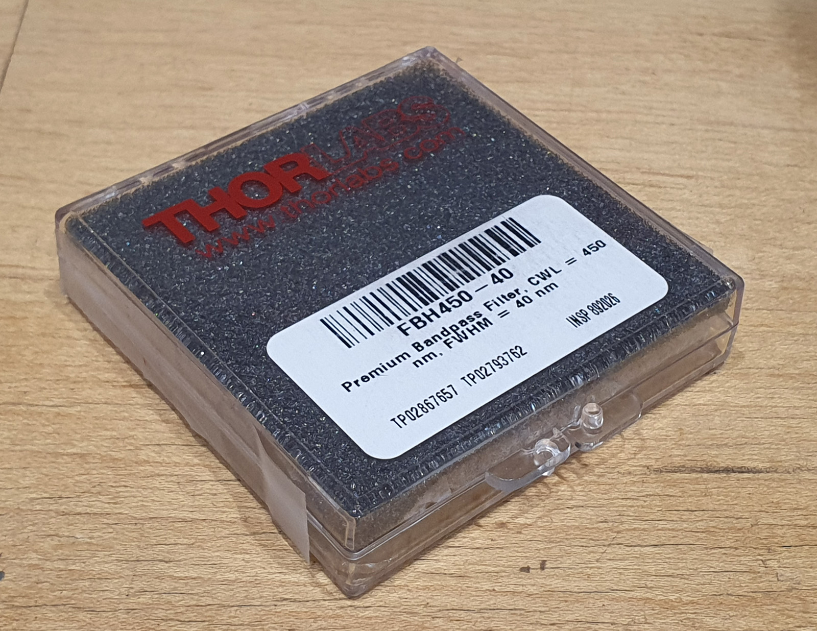
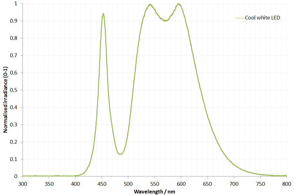
The filter is dichroic and has a preferred direction for the light going through it. This is shown by the arrow on the side of it. The LED is use is a cool white one I got from ebay and made an adapter to fit my light. This is its irradiance spectrum (measured on my Ocean Insight FX USB spectrometer).
Cool white LED irradiance spectrum
As can be seen the LED gives a broad wavelength range, but actually a nice strong peak at around 450nm. This is why I chose this filter and not a 405nm or 400nm one. Also using 450nm vs 405nm or 400nm is good for normal unmodified cameras as typically the internal filters on them will start blocking light at around 400nm. As a result 450nm is a good compromise – short wavelength, but detectable by normal cameras. Also the Thorlabs 450nm filter I used had a wide bandpass of 40nm, allowing plenty of light through. A 10nm bandpass filter would give a narrower range of wavelengths, but much less total light.
This can also be done (and was done historically) by putting a blue filter below the stage. I prefer to have the filter as the last stage before the light reached the camera though, which is why I put the filter on top of the eyepiece.
Of course a blue LED could be used, but as the white LED had a strong peak, I went down the route of filtering the light rather than having yet another light source.
A simple modification, but a helpful one when it comes to diatom imaging, adding a blue filter can produce higher resolution images for a given optical setup when compared with normal white light imaging. As always, thanks for reading, and if you’d like to know more about my work I can be reached here. Oh, I nearly forgot. Here is the slide I used for the images. While is says ‘Surirella gemma‘ on it there are plenty of Pleurosigma angulatum as well.
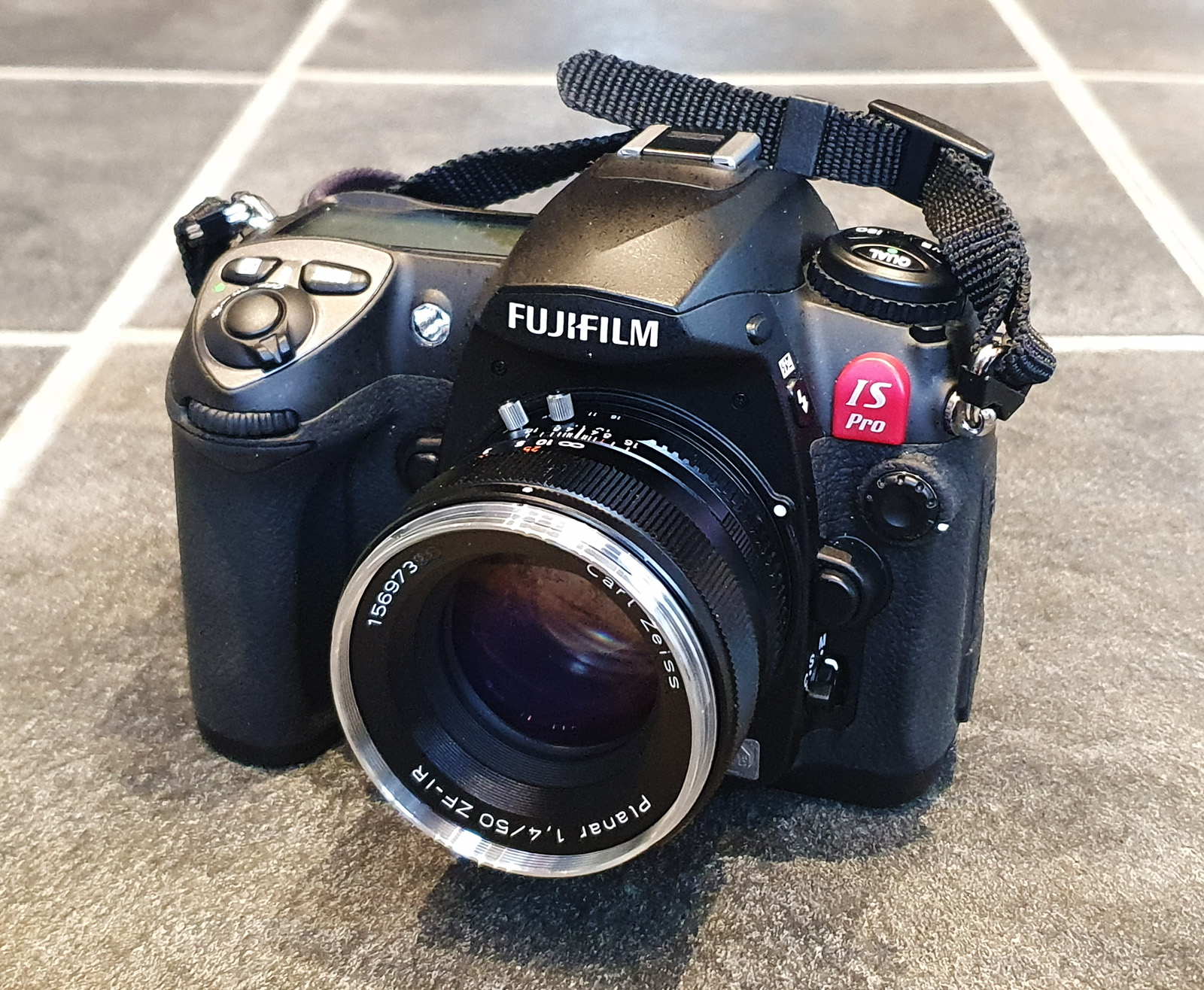
The Fuji IS Pro camera (or to give it its full name the Fujifilm Finepix IS Pro) was a DSLR introduced back in 2007. Based on their S5 camera body (which was based on a Nikon D200) this was advertised as being able to image in the UV, visible and IR and as such was not really aimed at the consumer market but more at the scientific and forensics areas. Indeed it didn’t go on general release and Fuji required buyers to sign a release form saying they weren’t going to use it for ‘unethical purposes’. It followed on from their S3 Pro UVIR version, but even from the beginning it was apparent that all was not well with the IS Pro and its UV sensitivity especially was not that great. I recently got hold of one these cameras and thought it would be fun to measure its spectral response as I have done with my other cameras.
Before we begin with the technical stuff, here’s the camera with a Zeiss ZF-IR 50mm f1.4 lens attached.
Fuji IS Pro with Zeiss 50mm f1.4 ZF-IR lens
Handling it, I like the feel of it. It feels well made and nice and solid. It takes compact flash cards, and has an APS-C sized sensor. Speaking of the sensor, this was a quirky design. A 12.3 megapixel ‘Super CCD’ with two different types of pixels – 6.17 million S-pixels and 6.17 million R-pixels for enhanced dynamic range. The degree to which these are used together can be selected by the user from the menu on the back. Although not a huge resolution, the sensor (when used in the S5) was well regarded by photographers especially with regards to the skin tones it was able to produce.
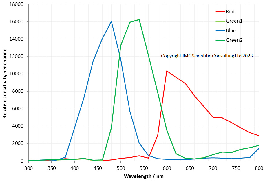
What’s the spectral response like? Here’s the results of my measurements.
Fuji IS Pro spectral sensitivity curve from 300 to 800nm
First thing to notice is this is barely UV sensitive, and only at the top end of the UV range from about 370-400nm. Below that sensitivity is essentially zero. The sensitivity it has is also mainly in the blue channel. This is different to the Sony, Nikon and Canon cameras I have looked at which have a little more sensitivity in the red and green channels in the UV, and a little more reach at the short wavelength end (for example see here for my Sony A7III data). While the IS pro could be used for imaging in that 370-400nm region, it is not really a UV camera. At the IR end things are better, and it is behaving here as expected for the other cameras which have been converted for multispectral imaging, although with a bit more emphasis on the red channel vs the blue and green channels in the 650nm to 780nm region.
However the really interesting area for the Fuji is how it splits blue, green and red. If you look at the Sony A7III for example, the red channel shows some significant response in the green and even blue wavelengths. Likewise the green channel spreads well into the blue and red channel regions. The Fuji IS Pro has very clean colour channels – while the overlap at their edges they do not spread over wide wavelength ranges, and the red does not bleed across the blue for example. This might account for its ability to capture skin tones accurately. I can also imagine it would be good at blue subjects – the Bluebell test, for example.
This IS Pro cannot be used simply like a normal colour camera given its IR (and the a lesser extent UV) sensitivity. However by using a filter such as BG38 on the front of the lens could be used for normal colour imaging, although the images would probably need to be carefully white balanced to get the best from them. I have also heard that IR photographers like it for the images it produces, so this is something I will try out.
Over the years, camera manufacturers have played around with different sensor technologies and each have their own little quirks and subtleties with regards to how they capture colours. Taking a look at the Fuji IS Pro has certainly been interesting, end despite its relatively low resolution compared with today’s offerings I can imagine it would still earn a spot in the camera bag for certain subjects. As always, if you’ve made it this far I thank you for your time, and if you’d like to know more about any aspect of my work I can be reached here.
It’s no secret that I enjoy imaging diatom microscope slides. They provide delicate and detailed structures and push me to get better at the imaging process. I tend to buy second hand older ones to image. While there are vendors still making slides, I think the older ones tend to have more character, and many are still surprisingly clear and usable for a fraction of the price of newer ones. Today’s post shows some of the slides to arrive recently and discusses how the images were captured (note that images have been reduced in resolution for sharing here, and all have been tidied up a bit to get rid of dust/dirt from the camera sensor).
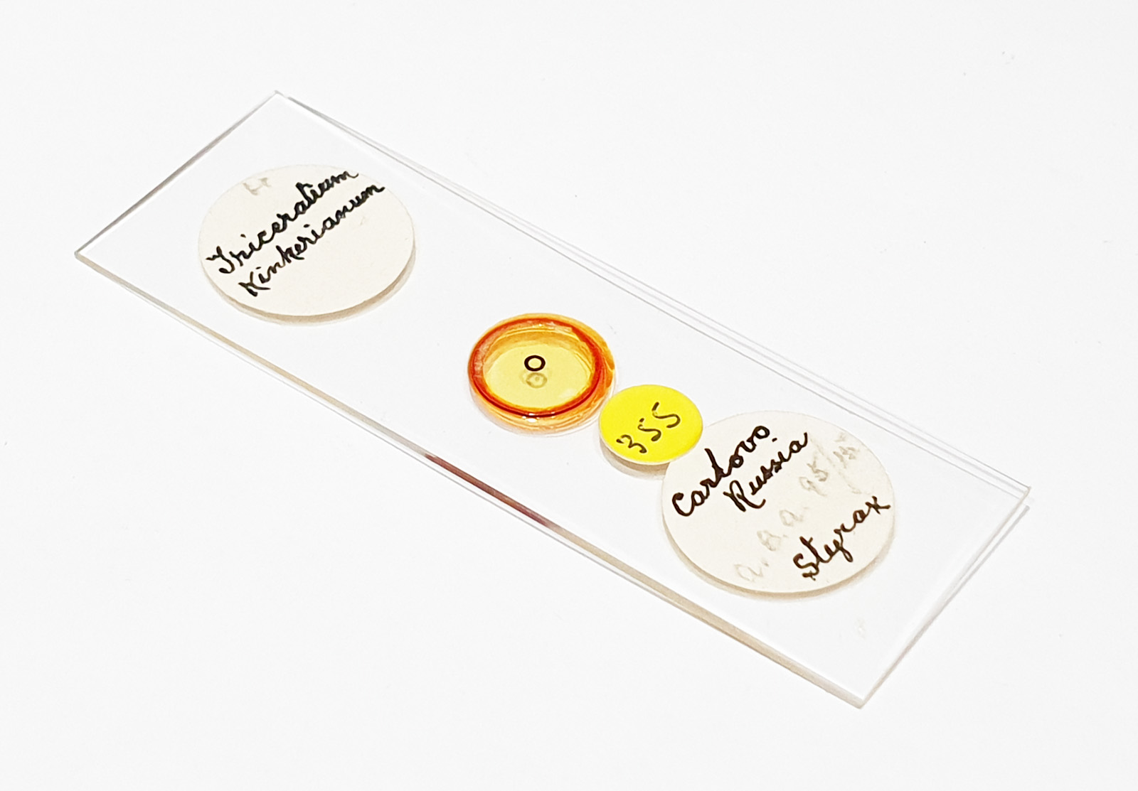
The first is a slide with a Triceratum kinkerianum diatom mounted in Styrax.
Triceratum kinkerianum mounted in Styrax
There is only a single example on the slide, so it took some finding as it is very small. This was lit using oblique lighting from below (Olympus Aplanat Achromat condenser) with the condenser set to still produce a bright field image, but one which has obvious side lighting, as can be seen by the shadows in the image. The objective used here was a 20x Olympus Splan NA 0.46, and the camera my Nikon d800 monochrome conversion. White LED light was used. Here’s the slide itself.
Triceratum kinkerianum slide
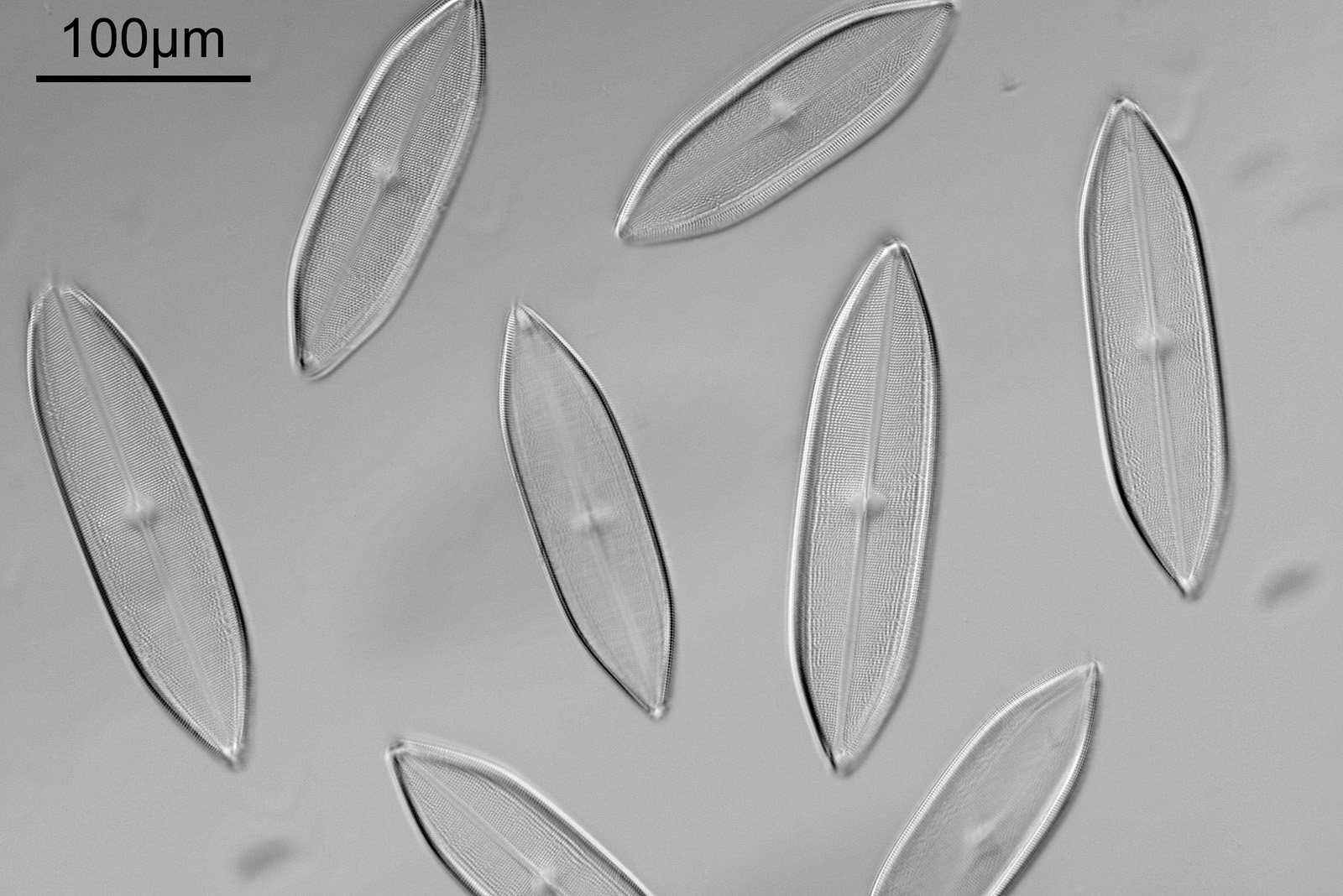
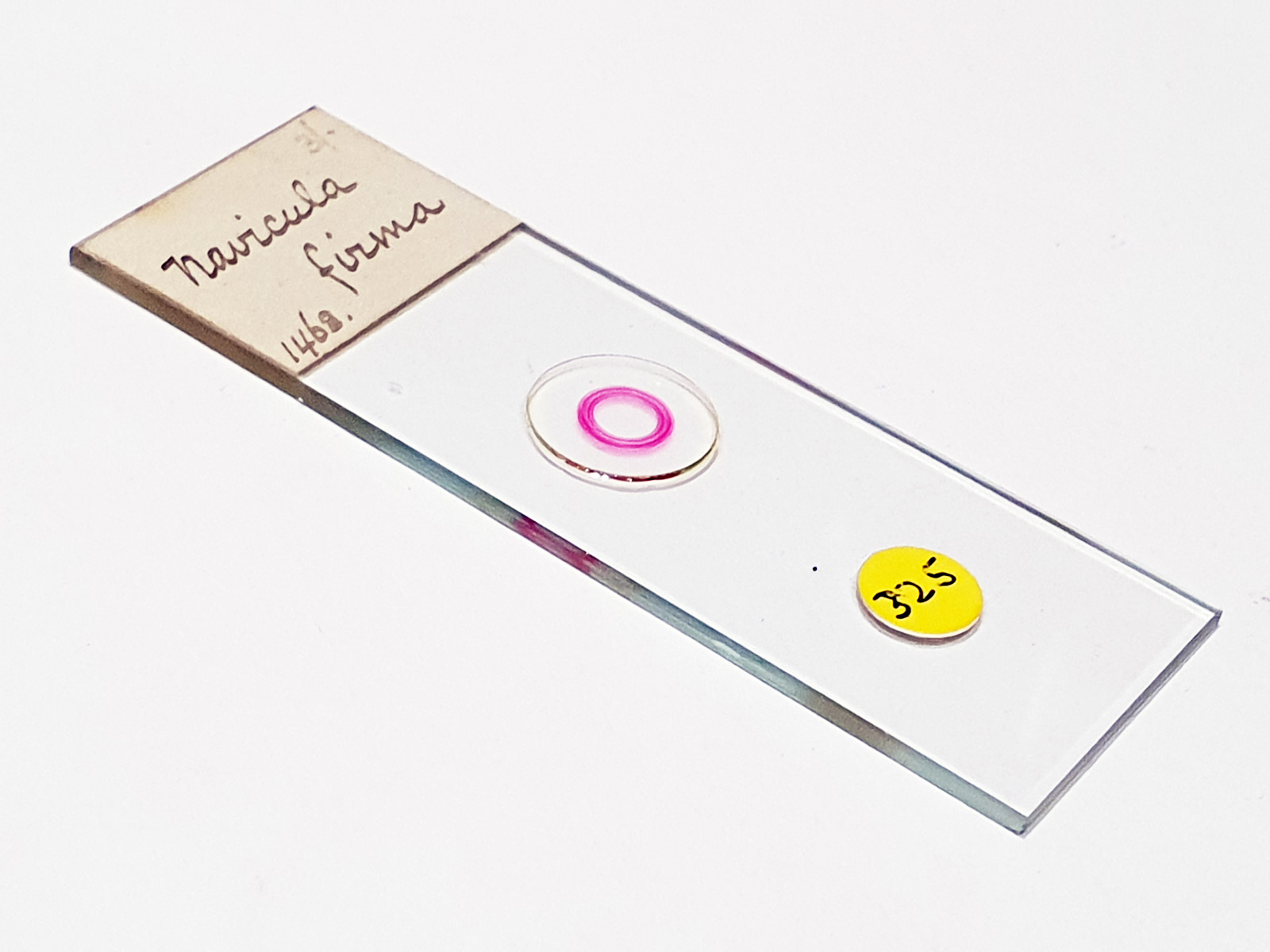
Next up is a Navicula firma slide. This has multiple examples of the diatom and was again imaged using oblique light from below, and with the 20x Splan objective.
Navicula firma slide
The diatoms are quite large but show some lovely features and will be well worth coming back to at a later date to look at in more detail. Here’s the slide.
Next is a diatom and spicule strew made by Eduard Thum (one of my favourite slide makers). This was also imaged using oblique lighting from below and with the 20x Splan objective.
Diatom and spicule slide by Eduard Thum
This slide is a strew so contains a wide selection of material to image. It seemed to lend itself very well to the oblique lighting, creating a great 3D effect. Here’s the slide.
Diatom and spicule strew slide by Eduard Thum
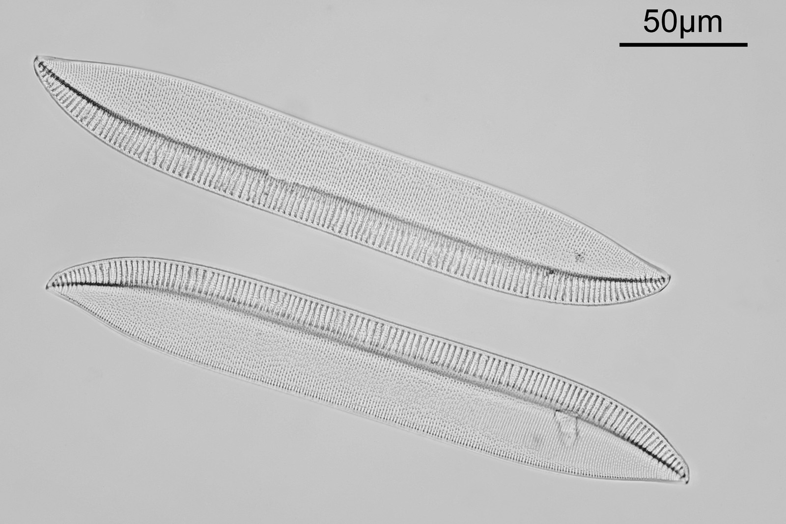
The final one for today is a Niztschia species slide by A.C. Cole. I spent a bit of time with this one. First a couple of images done with the 20x Splan objective.
Nitzschia slide, strongly oblique lightingNitzschia slide, straight bright field illumination
Both the images above where taken with the same condenser with light coming from below – an Olympus Aplanat Achromat. In the first image the lower part of the condenser was moved to one side. A small movement to the side produces oblique lighting and nice shadows, however a larger movement (or closing down the iris further) as done here, produces a dark field effect with a black background. This can be very useful for highlighting features in the diatoms. In the second image the lower part of the condenser was returned to the middle, and normal bright field imaging was done. The resultant image is relatively low contrast, and it is harder to see some of the features of the diatoms. How you light the sample has a huge impact on how it appears.
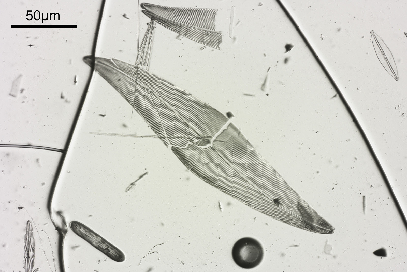
Next I imaged the same slide with a 40x Olympus Dplan Apo UV NA 0.85 objective. This has a coverslip thickness correction collar, and as the mounting of the sample had suffered over the years, the coverslip had tipped up slightly on one side. So I adjusted the correction collar to it’s max thickness (about 0.22mm). I also used 450nm filtered light to try and squeeze a bit more resolution out, and I set up the condenser for slightly oblique illumination. I did a stack of 7 images in Zerene stacker. This was the final image.
Nitzschia slide, slightly oblique bright field illumination
The higher resolution from using a higher NA objective and 450nm light is evident. The keen eyed amongst you will also have spotted the diatoms have been rotated by 180 degree from the images with the 20x objective. I took the slide off during imaging and must have put it back on the other way around when I returned it.
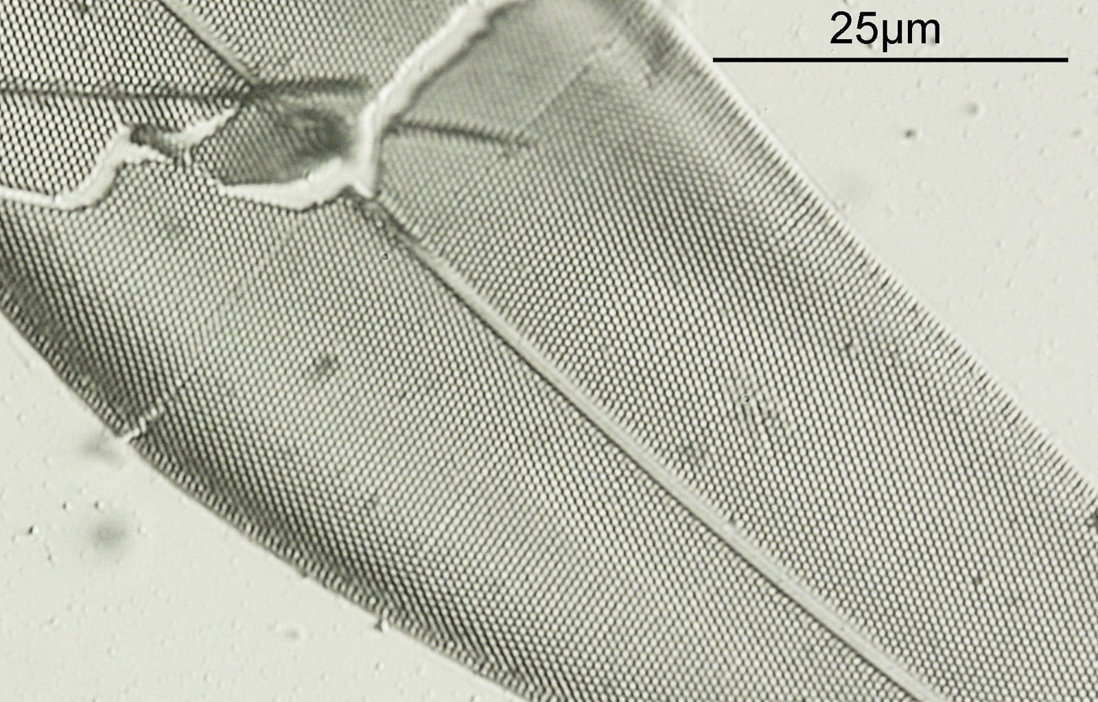
Stacking diatom images can be a challenge, as when the focus is changed different parts of the structure not only come in and out of focus, but look different as a result of the way light passes through the diatom structure. This can be seen in the video clip below, where I moved the stage upwards as the video clip was captured.
Here’s the slide.
Nitzschia slide
This is an interesting slide, with the label on the back, so effectively the slide needs to be turned upside down to image (in the photo above the sample and coverslip are on the underside of the slide).
There are always plenty of diatom slides for sale on places like eBay, and while some go for high sums of money, others can be had for a few pounds. Some of the historic microscopists were capable of producing fantastic slides and as such these are a great way to get some beautiful slides to image. With imaging lighting is key, and changing the lighting setup can have a huge effect on the final image. As always if you have made it this far thanks for reading, and if you’d like to know more about my work I can be reached here.
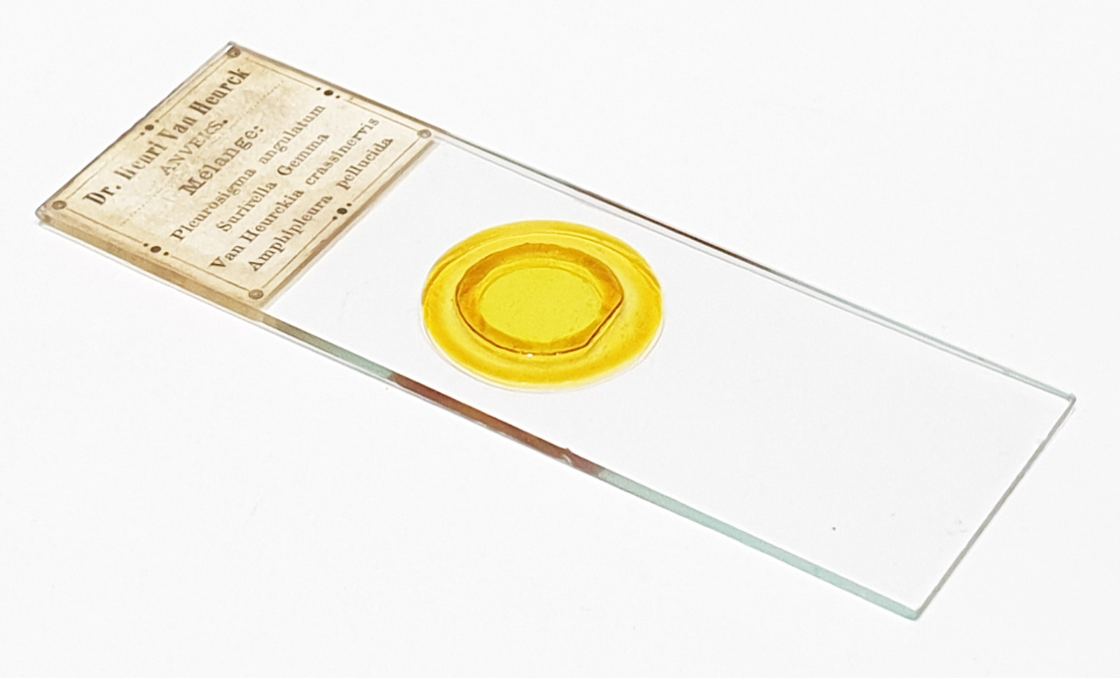
Microscopists have become very inventive when it comes to finding mounting materials to make the subjects they are imaging more obvious. One way of doing this with diatoms is to use something with a high refractive index (RI). While organic based mounts can provide some improvement, some of the inorganic mounts have very large RIs, and as such are able to produce slides with very good contrast. Metal and metal oxide slides are one approach (such as the work by Horace Dall which I have discussed here and that of John Dale, see here). Another approach is the use of arsenic sulfide (known by mineralogists as Realgar). I am currently in the process of writing a couple of research articles, one on metal and metal oxide mounts, and another on Realgar mounts, which I hope to publish later this year. For now though I wanted to share some images from a historic Realgar slide made by Henri Van Heurck.
The slide was likely made sometime around the 1880s, and is a strew of a number of different diatoms mounted in Realgar. I’ll show a picture of the slide later, but for now here are some images from it, captured on my home built Olympus BHB microscope.
Pleurosigma angulatum on the Realgar mounted Van Heurck slidePleurosigma angulatum on the Realgar mounted Van Heurck slide, crop from main imageSurirella gemma on the Realgar mounted Van Heurck slideSurirella gemma on the Realgar mounted Van Heurck slide, crop from the main image
The images above were captured using a 40x Olympus Dplan Apo UV objective (NA 0.85) and with oblique illumination from below. The high contrast the mount provides is evident in the images. They were produced using white LED light and the mount itself is a yellow colour, as can be seen below.
Dr Henri Van Heurck, Realgar diatom slide
Realgar slides are delicate and light sensitive, so effort must be taken to store them in the dark and only expose them to light during imaging. Very often the slides show cracking of the Realgar and this is evident here as well.
It should be mentioned that making the slides is a hazardous process, and should only be attempted by someone familiar with the use of dangerous chemicals. This is probably one of the reasons why the technique is no longer done.
I have a number of Realgar slides in my collection now, and as mentioned above aim to write a paper about these fascinating historical items later this year.
As always thanks for reading, and if you’d like to know more about this or other aspects of my research, I can be reached here.
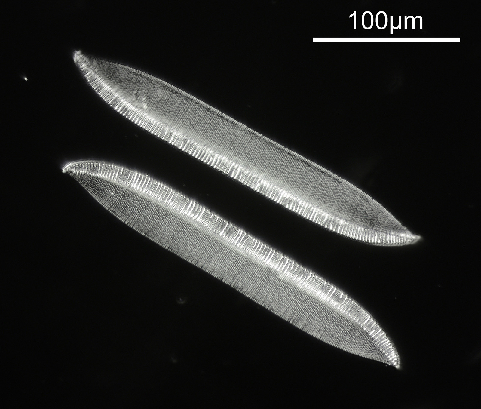
A bit of a fun experiment today. The images we create depend greatly on how we light our subject. Changing the lighting can have a drastic impact on the final appearance of the photo. This post shows how using a historic Watson Holoscopic condenser can be used to image diatoms, and how the picture look compared with straight brightfield, and oblique illumination.
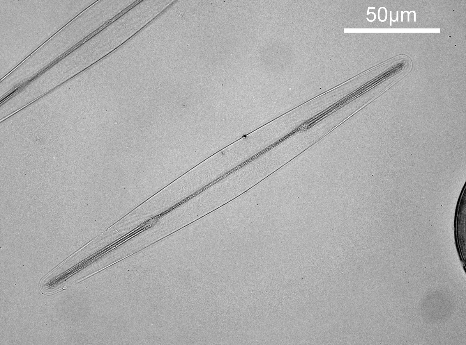
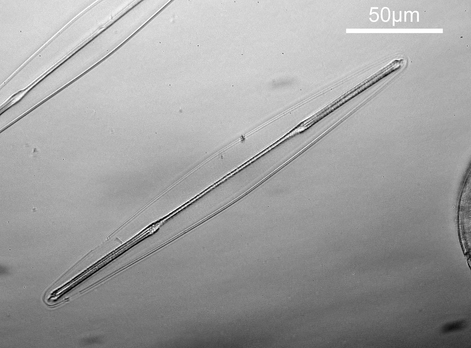
The subject was a Darlaston slide with two Amphipleura lindheimeri diatoms present and a two circular diatoms as well. The microscope was my usual modified Olympus BHB. Objective was a 40x Olympus UVFL PL NA 1.3 silicone immersion one with an adjustable iris (the adjustable iris was important for this experiment, more on that later). I used 450nm filtered LED light, and images were captured on my monochrome converted Nikon d800 camera. For condensers I used an Olympus Aplanat Achromat one (normal brightfield and oblique brightfield) and the Watson Holoscopic condenser. For both of these I oiled them to the underside of the slide using immersion oil, and I also used that for the objective. The objective was designed for silicone oil, but I didn’t have any of that, so just used immersion oil. In hindsight apparently 50% glycerine in water might have been a better bet, but for now the experiment was done with immersion oil.
Enough chat, what do the images look like. Note, I’ve reduced the images resolution for sharing here. First with the Watson Holoscopic condenser.
Image of A. lindheimeri using a Watson Holoscopic condenser
Next with an Olympus Aplanat Achromat condenser, in normal brightfield mode.
Image of A. lindheimeri using an Olympus Aplanat Achromat condenser, normal brightfield
And finally, with the Olympus Aplanat Achromat condenser but in oblique mode.
Image of A. lindheimeri using an Olympus Aplanat Achromat condenser, oblique brightfield
The Watson Holoscopic condenser gives dark ground (darkfield) appearance to the image, but for this to happen I had to stop down the iris on the 40x Olympus objective slightly – fully open it didn’t produce a dark ground image as the objective NA was too high. This is why it was important to use an objective with an adjustable iris for this experiment. It was probably just below NA 1.0. The iris on the objective was then left the same for the images with the Olympus Aplanat Achromat condenser. The low contrast of the normal bright field image can be seen, as well as the improvement in 3D appearance with the oblique condenser. In these full size images though the Watson Holoscopic condenser looks to show the features of the diatom quite well.
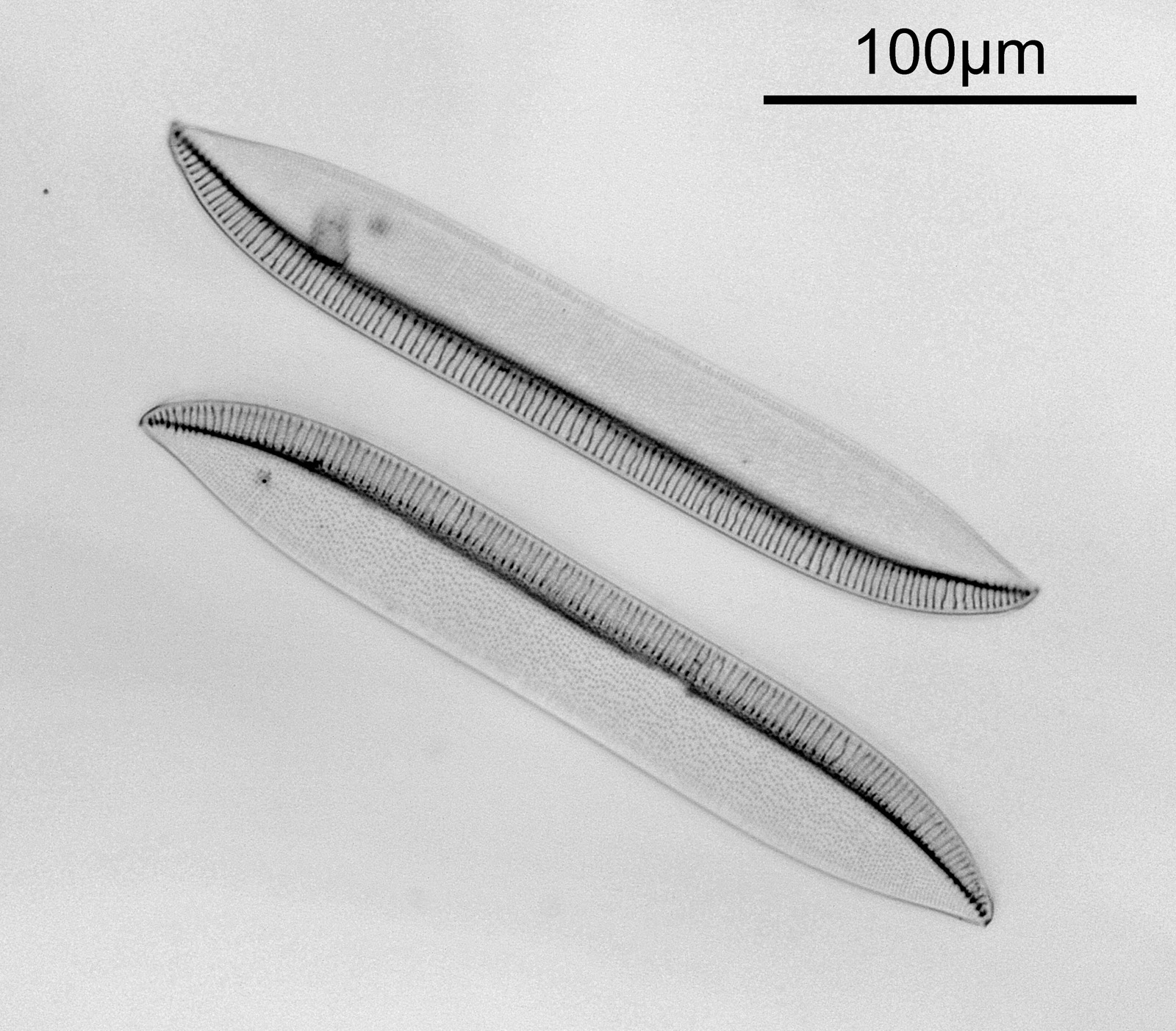
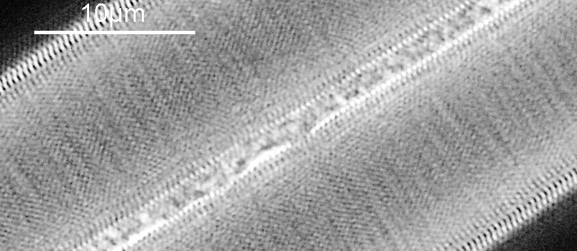
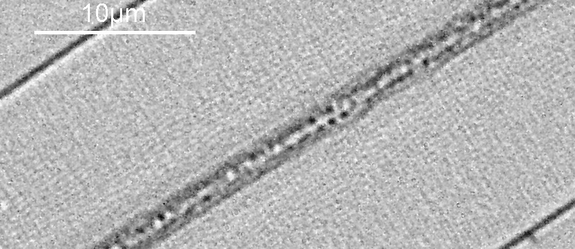
Crops of the 3 images show a bit more of the detail they can reveal.
Cropped image of A. lindheimeri using a Watson Holoscopic condenserCropped image of A. lindheimeri using an Olympus Aplanat Achromat condenser, normal brightfieldCropped image of A. lindheimeri using an Olympus Aplanat Achromat condenser, oblique brightfield
The benefits of oblique illumination over normal brightfield for the diatoms can clearly be seen in these cropped images. The Watson Holoscopic condenser also seems to be highlighting some of these features, especially at the edges of the diatom and along the central ridge.
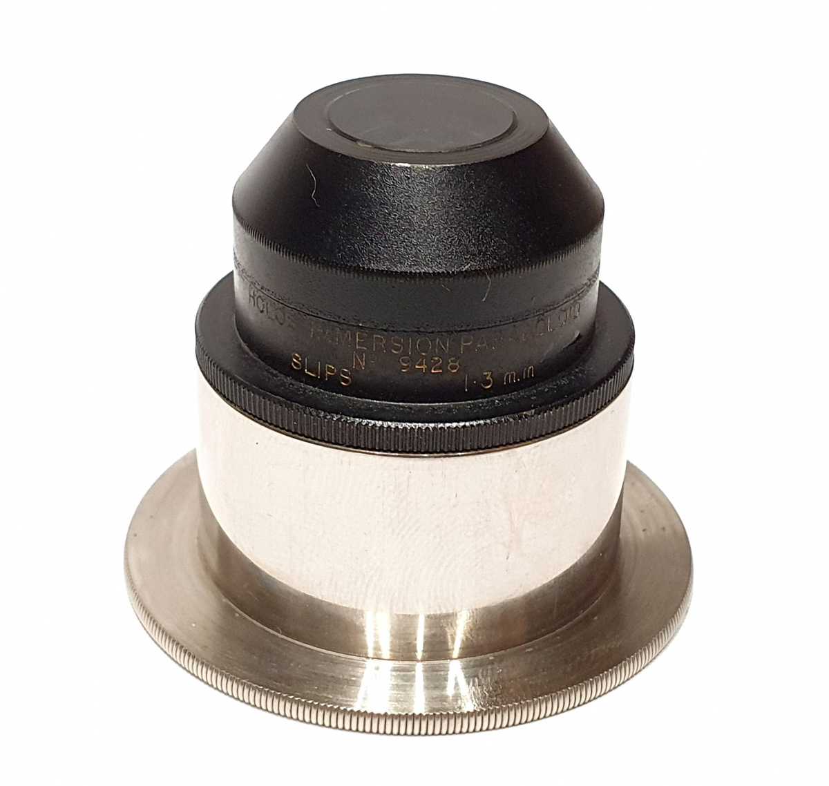
What is the Watson Holoscopic condenser? Here’s a picture of it.
Watson Holoscopic condenser
And an excerpt from a 1930’s Watson catalogue which provides some information about it.
This shows why an adjustable aperture on the objective is useful, as with oil immersion objectives is requires an aperture of less than NA 1.0. It should be noted that the condensers were designed to be used with slides of specific thickness (this one being 1.3mm) so the slide used here was perhaps not ideal for this specific condenser.
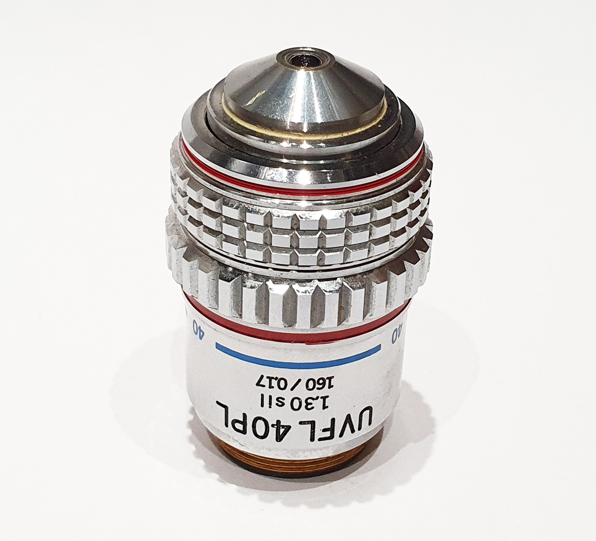
The objective was quite an unusual one – a 40x Olympus UV FL PL NA 1.3 silicone immersion one with an adjustable iris.
This is designed for UV fluorescence work, (‘UVFL’ on the barrel) so has quite good transmission in the upper UV region. It is also a phase contrast objective (the ‘PL’ on the barrel). It was meant to be used with silicone oil, although I just used normal immersion oil. I should have tried glycerine and water mix, as I have since read that that would be a better match to the silicone, but ‘every day is a school day’ as they say. Although not labelled as such it also has an adjustable iris to reduce its NA. This can be seen by looking through the objective when the knurled iris ring is rotated. This feature makes with useful for dark ground imaging, where tuning the objective NA to the condenser can optimize the image.
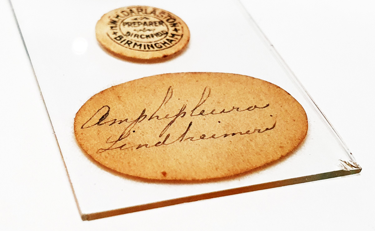
Finally a couple of shots of the slide itself. This was picked up on ebay for few pounds (GBP).
The original makes label says W.H. Darlaston of Birmingham, who is a well known slide maker. But is also labelled with T. Frankish, B.Sc, who I am guessing was the owner of the slide.
The Holoscopic condenser is a relatively simple construction, and I am wondering if it possible to make one of these using quartz or fused silica. If so it would be possible to use it deep into the UV which should allow for some very high resolution imaging. But that is for another day. As always thanks for reading, and if you’d like to know more about this or any other aspect of my work, I can be reached here.
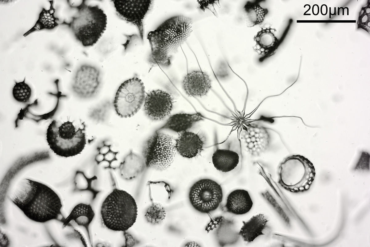
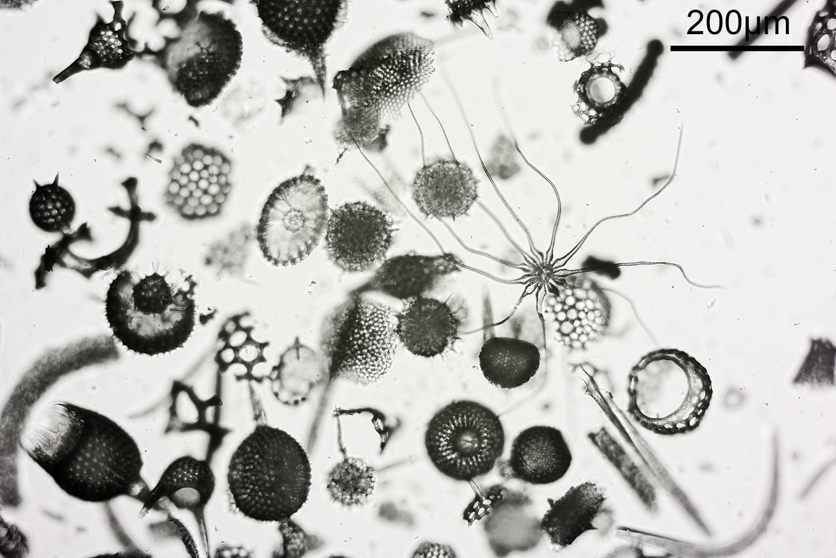
I’ve been busy with work, but last night took a break to look at a microscope slide which arrived recently. It was described as a ‘Polycistina’ slide from Barbados and it had an unusual feature on it.
Here’s a couple of pictures of the slide taken using different iris settings on the condenser.
Polycistina slide, condenser iris setting 0.4 – shallow depth of fieldPolycistina slide, condenser iris setting 0.2 – greater depth of field
The unusual feature is the one with tendrils, and it has been mentioned that this could be a plant trichome. In the images above, there were two settings used for the condenser iris – the first one was open to NA 0.4, and the second one it was closed down to about 0.2. Everything else was the same between the two images (Nikon d800 monochrome camera, 10x Olympus UVFL NA 0.4 objective, white LED light) although exposure time was increased for the smaller iris aperture. This shows the effect that iris aperture setting can have on depth of field in an image. Closing down the aperture too far though can be a bad thing due to diffraction starting to occur, and also a shallow depth of field helps emphasize the subject. As with many things in life choosing what looks right is a balancing act.
The sample is quite thick, and as the stage was moved up and down different parts of the image came in and out of focus. This can be seen in the video below where the stage was gradually moved up.
It was actually quite interesting to view the slide using a low magnification (4x) objective. The sample was so thick that slight movement of my eyes when looking at it through the eyepieces gave a ‘3D’ image as the features moved differently depending on their depth in the slide.
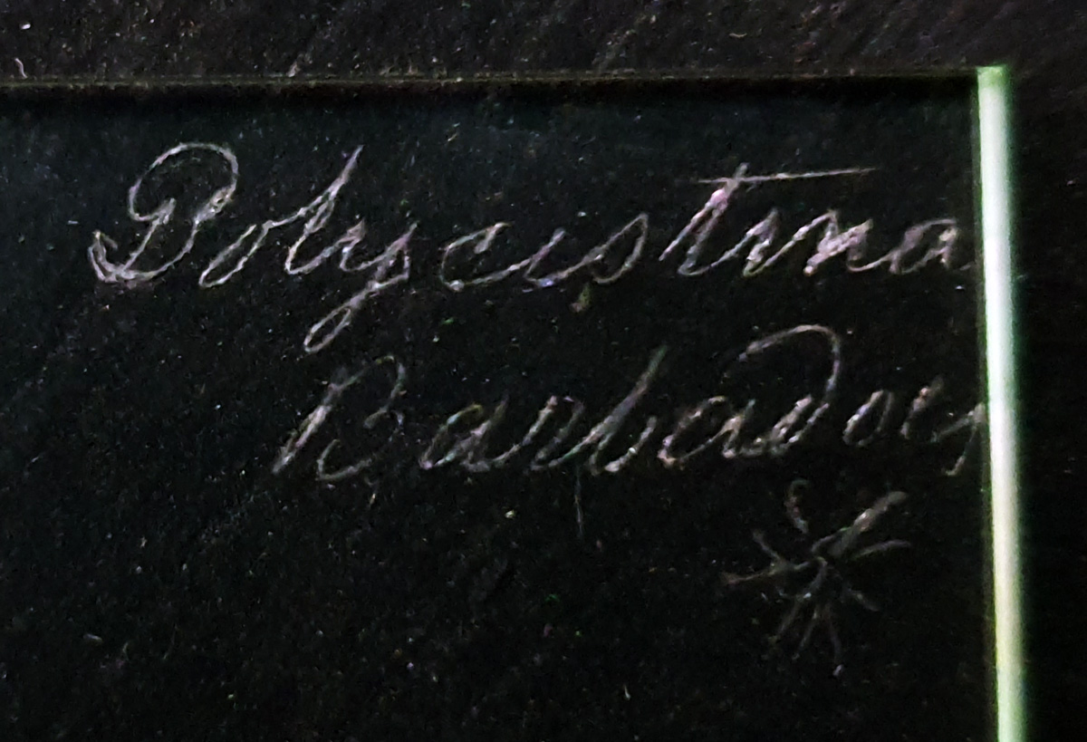
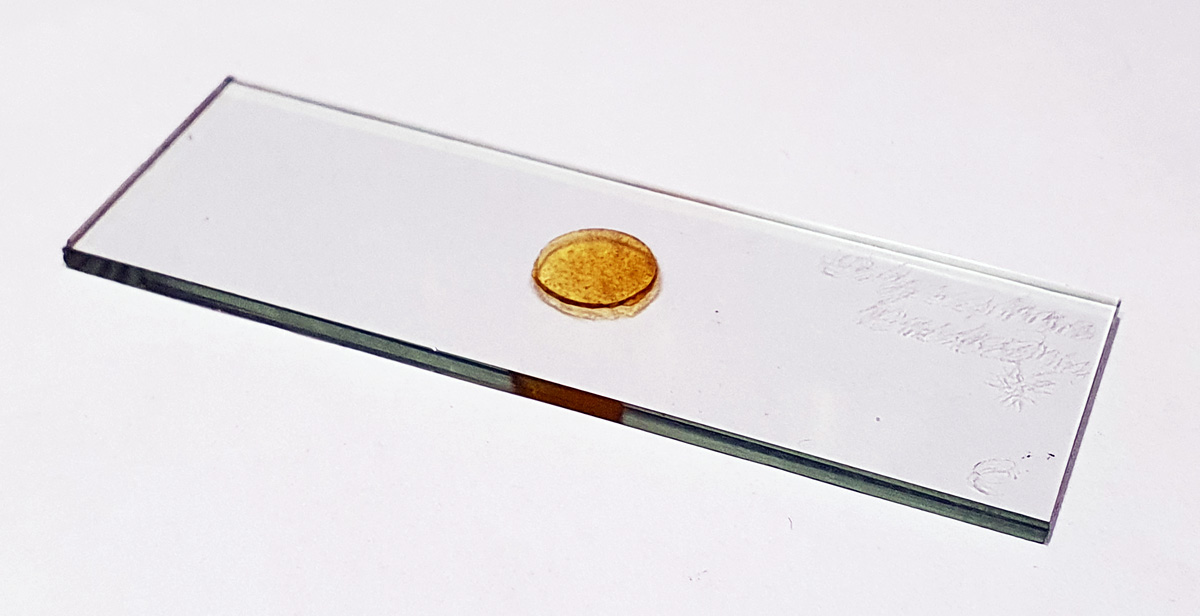
The slide itself is interesting and the maker even engraved the shape of the unusual feature onto the slide. Unfortunately there is no makers name. The slide itself is very thick.
Label on the slide, showing the ‘feature’ at the bottom rightThe sampleThe slide
Microscopy continues to fascinate me, providing a window in to the wonderful world of the tiny and the amazing structures that nature can produce. As always, thanks for reading, and if you’d like to know more about this or any other aspect of my work I can be reached here.
‘Life is not an exact science, it is an art’. A quote by Samuel Butler, and much as though the scientist in me would like to control every aspect of my life and my work, it does not always work out like that. Sometimes we cannot rely on science alone and must resort to gut feelings based on experience and understanding of the problem. In building my UV microscope there have been many challenges – the optics can’t be made of glass, the camera sensitivity needs to be increased, and what to do about the lighting? Having dealt with the optics and the camera, the lighting has been an issue for me lately. At 313nm and 365nm, a mercury xenon lamp is a good option. Nice strong emission lines and focussable. Below 300nm things get tricky. I did build a 254nm source using a low pressure mercury lamp, and that did enable me to get some images with the microscope, but it has it’s challenges. While it has a nice sharp line at 254nm, it does still require filtering to remove other emission lines, and while the efficiency is high for producing UV the overall power is low. Also it emits light 360 degrees, so I can only harness a fraction of what it produces. What I needed was a better light, and this is something that has kept me awake at night for quite a while. In the end I settled on a deuterium light source. Plenty of UV, especially in the 200-300nm range, which was just what I needed, along with relatively little visible and IR light. However what I couldn’t find was a direct comparison with the little 3W low pressure mercury lamp I had. In the end I just had to jump in based on a best estimate and a gut feeling.
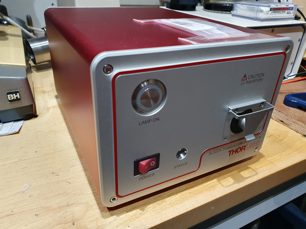
The light source I went for was a Thorlabs SLS204 deuterium lamp. The main reason for this being that the fiber port could be removed, and there was a SM1 thread present to allow me to easily attach things like condenser lenses and other optics to focus the beam. Here’s the light source.
Thorlabs SLS204 deuterium light
The fiber port where the light comes out is underneath the protective cover on the right hand side. The cover, and the black circular part which holds the fiber port underneath can be removed to reveal the deuterium lamp and that is where condenser lenses and other optics can be attached. That is a big tick Thorlabs. Couple of things are not big ticks though. The tool to remove that black circular piece is not included with the light, so I’ll need to order that separately (and pay for more postage, grrrr). Also there is no internal shutter for the light, unlike on my Ocean Insight one. As such when the deuterium lamp is on and with the safety cover removed, there is nothing to block light coming from the lamp housing. This could be a safety issue for my application, and as such I’ll need some form of manual shutter or at least an iris to reduce the output. Not ideal.
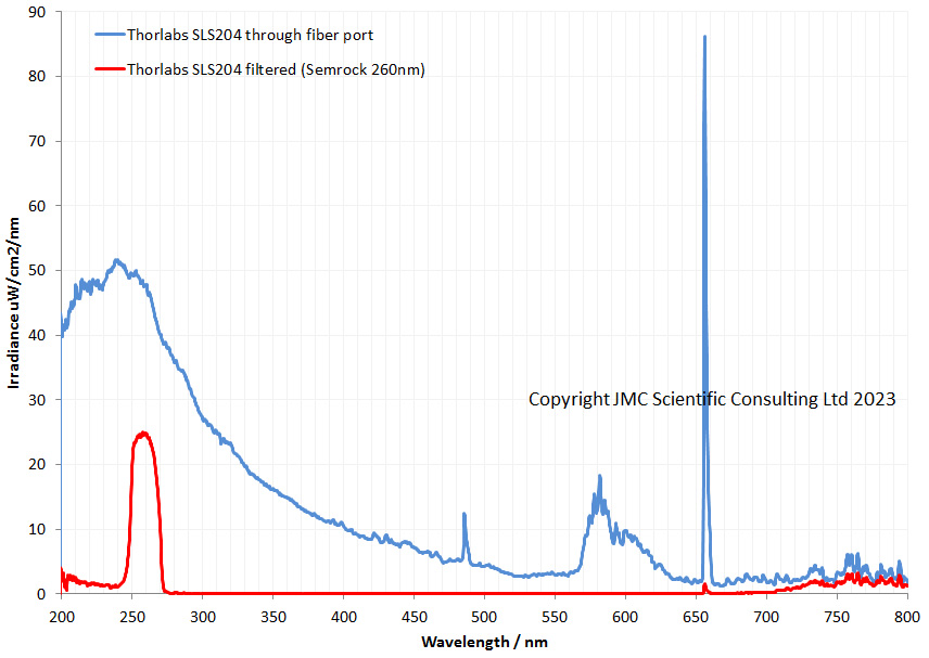
Enough of my moaning. How does the output spectrum look? As a first look I just put the fiber (with a cosine corrector) from the Ocean Insight FX spectrometer up against the output port of the light. I then also put a Semrock 260nm brightline filter in place, as this blocks most of the visible and even some of the IR to get an idea of how effective it would be. These were the spectra produced.
The light produces the as expected profile for a deuterium lamp. Lost of UV and a strong line in the visible at about 655nm. The Semrock filter does a good job of removing the long wavelength UV and a lot of the visible up to about 700nm but after that doesn’t offer any additional blocking. Will this be good enough on it’s own? I am not sure about that, and that remains to be seen. The good thing is that it lets plenty of light through in the 250-270nm region, and is not a line spectrum like the low pressure mercury lamp. This should help with its use as a source for microscopy.
Is the deuterium lamp the perfect solution? Well, no, unfortunately not. It still requires filtering, and it is not as intense as a low pressure mercury light. However it offers a continuous spectrum with plenty of light in the 250-300nm region and as such is worth exploring, despite the hefty price tag. The next step is to get a condenser lens in there and build an adapter to fit my microscope. The light also might be useful for UV photography in the 200-300nm region, so that is something else to think about in the future.
Science doesn’t always go to plan, and at some point many of us are faced with making decisions based on our best estimates. While this is scary, it is part of science, and is something which needs to be dealt with if you want to make new discoveries. If we knew all the answers there would be no new discoveries. Thanks as always for reading, and if you’d like to know more about this or any other aspect of my work, I can be reached here.
While we are used to seeing the world in the visible spectrum, moving outside of that into either the Ultraviolet (UV) or Infrared (IR) regions can make scenes look very different. During a trip to Tasmania I took one of my multispectral cameras with me to compared some landscape photography in the UV and IR with visible light images, and these are what I am sharing today.
The comparison images are shown in black and white, to remove the issues of whitebalancing non-visible images. A multispectral Canon EOS 5DSR was used along with an 85mm f4.5 Asahi Ultra Achromatic Takumer (which has quartz and calcium fluoride lens elements instead of glass to allow it to transmit UV). The following filters/filter combinations were used in order of increasing wavelength range;
UV – Baader U
UV/Visible – Chinese BG39 2.5mm alone
Visible – Chinese BG39 2.5mm + B+W486
IR – Hoya R72
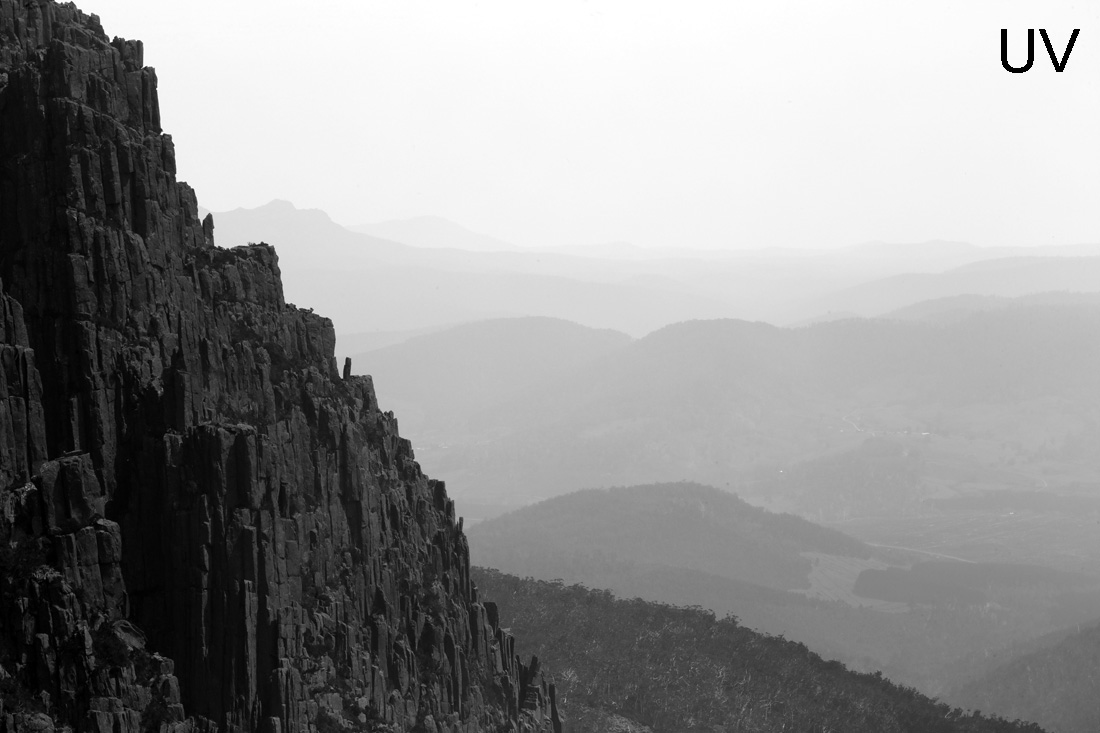
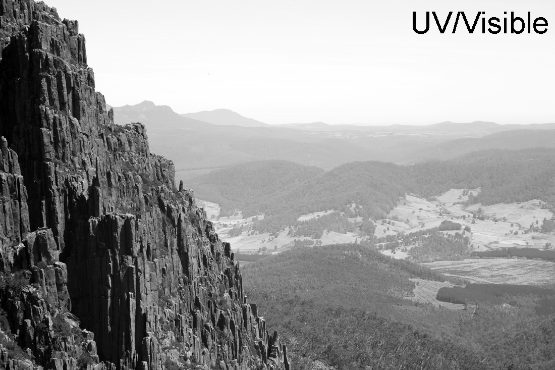
First set of images – The view from Ben Lomond.
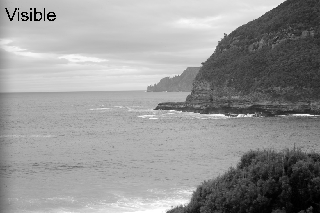
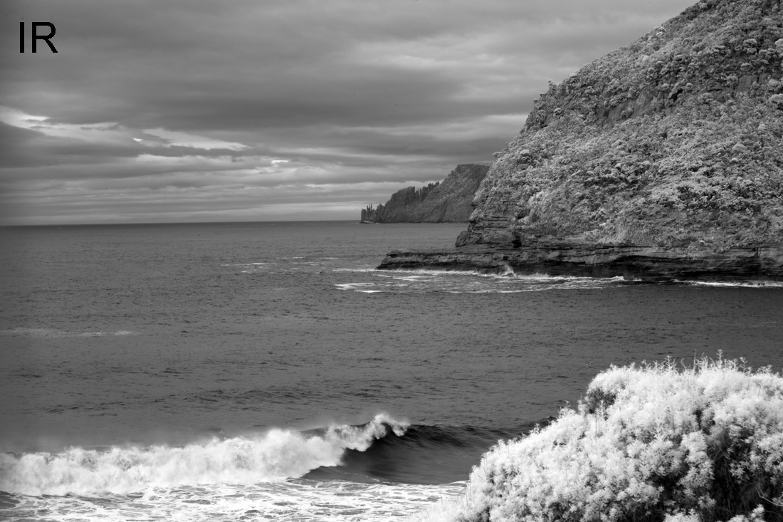
Note that the visible image here is actually UV+visible as the UV portion of the spectrum was not removed by the BG39 filter alone. However the UV contributes relatively little to the image, so the image should be considered as mainly visible light. In UV the haze is emphasized, making the distant landscape blend more into the sky. It also lessens the appearance of clouds making the sky look more homogeneous and giving more of a feeling of distance to the landscape. The contrast between bright sunlight and shadow on the rocks is also reduced and foliage is darkened. Conversely, in the IR image blue sky becomes darkened, foliage almost white, and haze is reduced.
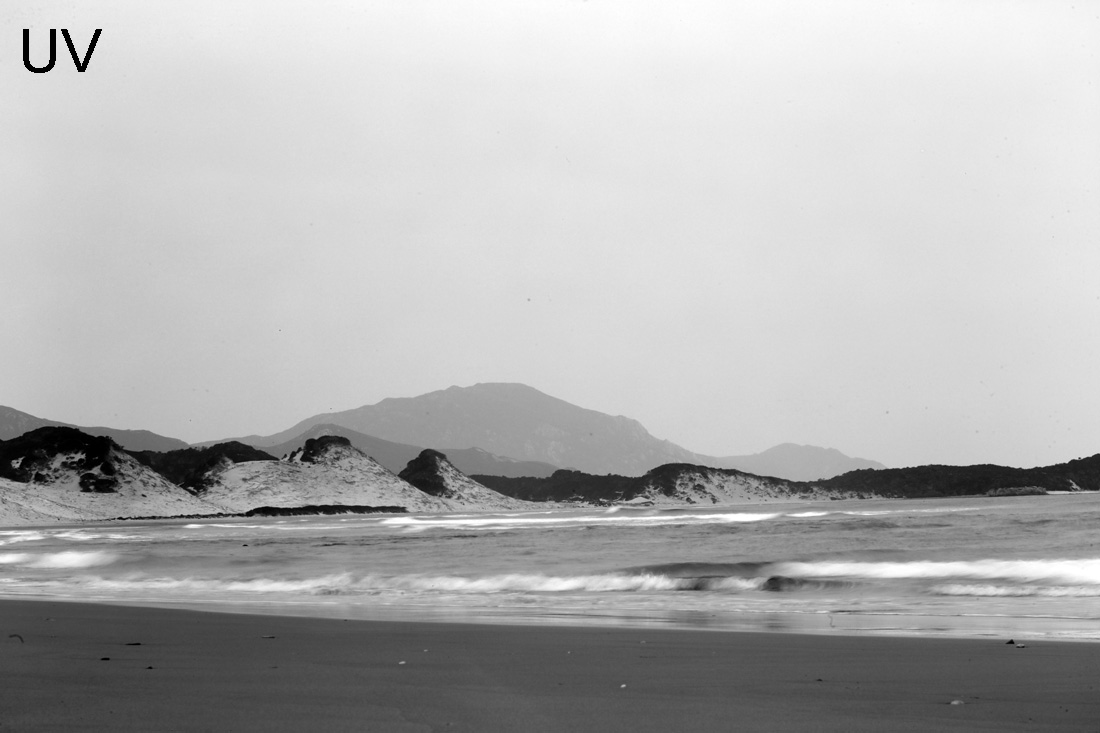
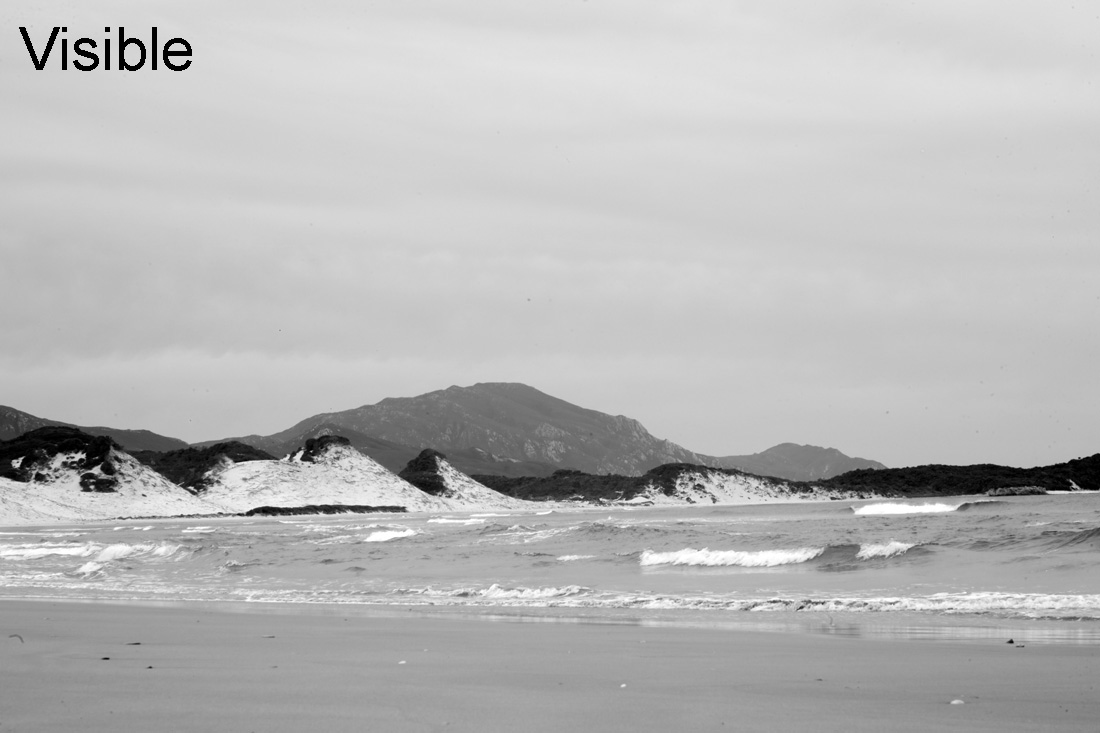
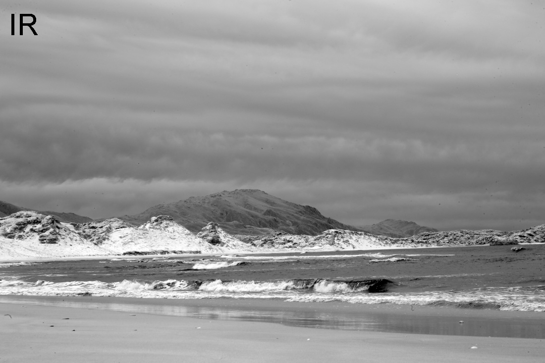
Next area Stephens Bay in the South West National Park, and about as remote as you can get (which is saying something in Tasmania).
It was quite a dull day when we were there, with no blue skies, but the effect of going from UV to Visible (this time a UV blocker was used in combination with the IR blocking filter) to IR can again clearly be seen. As an aside, this is a fascinating area and hugely culturally significant as there are Aboriginal middens along the beach which are full of shells and date back thousands of years.
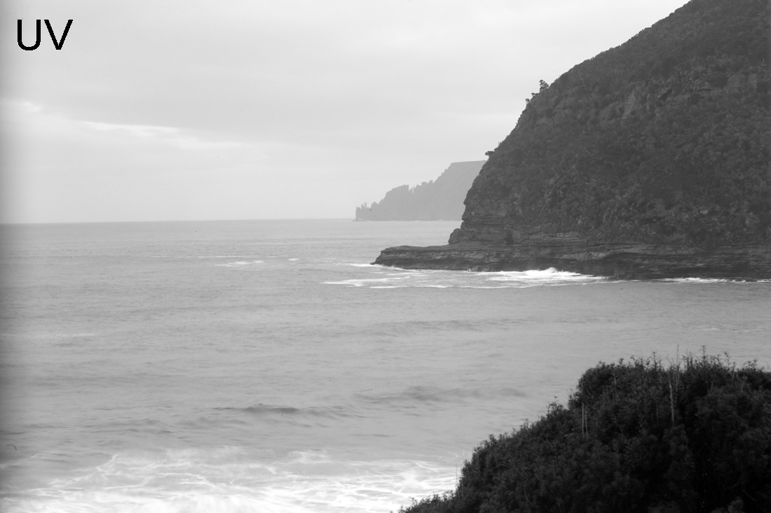
The final area for today’s post, the view to the dolorite spires of Cape Raoul from Maingon Bay Lookout at Remarkable Cave on the Tasman Peninsular.
Again these show the expected behavior going from UV through to IR.
Varying the wavelengths we use for imaging has a huge impact on how a scene is rendered, and this is as applicable to areas such as dermatology and forensics as it is to landscape photography. Thanks for reading and if you’d like to know more about this or other aspects of my work, I can be reached here.