Category Archives: General

UV Microscopy – modifying the binocular/trinocular head

Earlier this year I started my journey into the world of microscopy, and after a few weeks in thought ‘wouldn’t it be such fun to build a UV microscope’. This idea came along with all the optimism and naivety of someone who really didn’t know what he was letting himself in for. After all, I’ve been researching UV photography for a while and everything can just be reapplied, right. It’ll be easy, right. Well as Arnie said in Commando, that cinematic classic from the 80s, “Wrong”. Even though it has been challenging, it has been great fun and scientifically rewarding. You don’t really know how something works until it is in bits on your work bench.

A few weeks ago in an earlier post, I discussed about the glass elements in the binocular head which contains the eyepieces (covered here). The issue here was that the 2 elements – a circular window and a prism – which were present, blocked the short wavelength UV and would be effectively opaque below 300nm. Now this was a bit of a tricky situation. While I could potentially just get rid of the binocular head and have a tube which the camera would connect to, I wanted to keep the eyepieces and make it look like a normal microscope. To do this, there was only one thing to do, and that would be the replace the window and the prism with UV fused silica or quartz (or calcium fluoride) versions. The problem with this is that both parts would need to be custom made, and anything custom made out of these types of materials is expensive, especially something as complex as a prism made of multiple components.

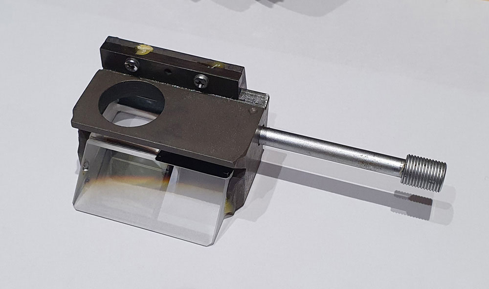
For help with this I approached UQG Optics, who I have bought filters from before and who have always been good to work with. After drawing up a set of plans they are able to make components in the sizes that I need. Firstly the window. Being a circular this was relatively easy, however the size was unusual so is a custom build. The prism presented more of a challenge. As shown in the previous post, the prism is held within a metal slider. A few screws loosened, and a bit of gentle persuasion with a thin bladed screwdriver, and the prism was released from its cradle to reveal the following.
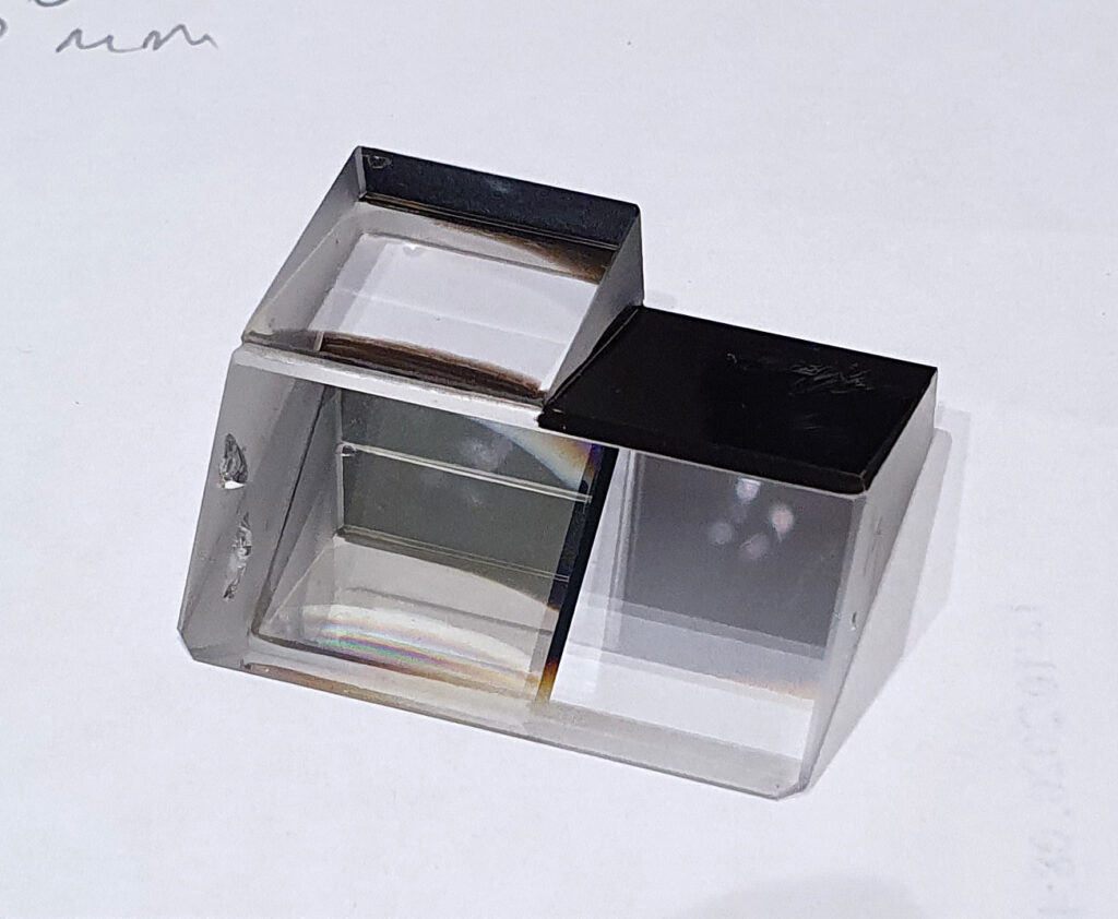
Binocular head prism

The prism is split into 2 halves – left and right in the image above. When the right hand side is slid into place, the light coming from underneath is bounced into the eyepieces, and none of it can pass directly upwards towards where the camera would be (when the vertical tube is added to the binocular head to make it a trinocular). When the prism is slid across so the left side of it is in the optical path, the light is split with some of it going to the eyepieces, and the remainder going vertically upwards to the camera. To replicate all of this in UV fused silica would be a stretch. It’s a big block of glass, and with some complex angles and shapes. Rather than trying to replicate the whole thing, I decided on a different approach – to cut the prism down the middle, and keep one half while replacing the other half with a simple block of UV fused silica. By keeping the right hand side of the prism, I can keep the side which directs light to the eyepieces and allows focusing. By replacing the left side with a block of UV fused silica, the light would go straight up to the camera. In this configuration, all the light would go to the camera, helping to improve optical efficiency and final focusing for the camera can be done using the live view function. The block of UV fused silica would simply be glued to the remaining part of the prism, and the whole thing mounted back into the the slider. Being a block with parallel sides that is smaller than the overall prism it is also much easier (and cheaper) to make.

Both the UV fused silica window and block have been ordered, and the prism will be sent off to be cut down and prepared. These should all be back with me in December, and are the last UV fused silica components required to convert the microscope.

In all of this the safety of the user (i.e. me) needs to be considered. UV light sources for microscopy tend to be high power, and when focused to tiny pinpoints are extremely dangerous. Couple this with the light then being passed through eyepieces, and the risk of eye damage becomes a very real threat. Retaining parts of the original glass prism for the light going to the eyepiece is actually an advantage here, as the glass itself will block some of the UV, especially the UVB. However there would still be a lot of UVA passing through. How to address this? I wear glasses anyway which have UV blocking layers on them, and I would also wear UV safety glasses when using the device, but it would also be good to have some UV blocking filters in the eyepieces themselves to block anything below 400nm. The eyepieces are 23.2mm diameter so rather than having some long pass filters custom made, I wondered whether there were any 23mm yellow camera filters out there. A quick on eBay search led me to Vintage Cameras Ltd, who had some yellow and orange filters in 23mm diameter for substantially less than they would have been to have custom made. There were two light yellow, two dark yellow and two orange filters as shown below.
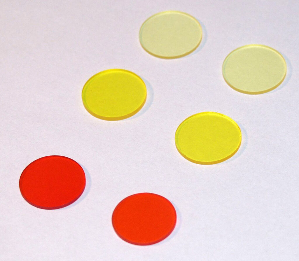
23mm filters

Measuring the transmission spectra of the filters using my Ocean FX spectrometer gave the following.
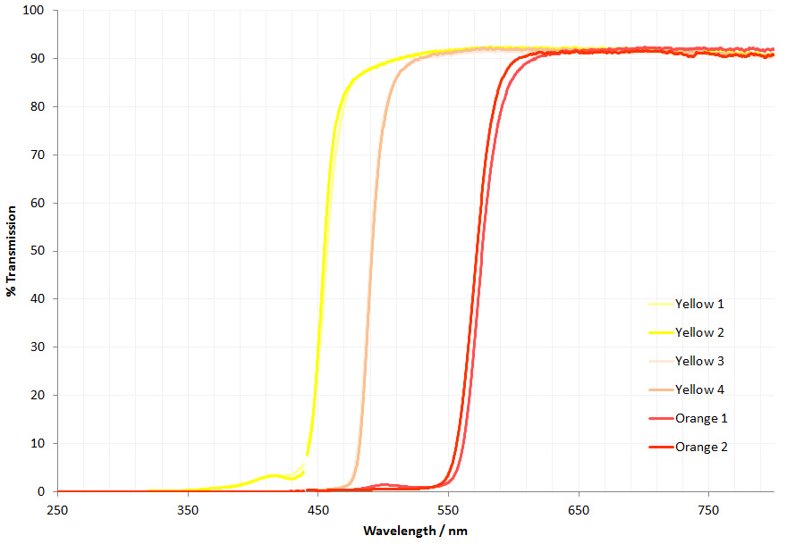
Transmission spectra for the yellow and orange filters

In the scan above, Yellow 1 and 2 are the light yellow filters, Yellow 3 and 4 the dark yellow ones and Orange 1 and 2 the orange ones (if that wasn’t obvious). Yellow 3 and 4 were almost identical, hence the lines overlap. All showed well defined long pass behaviour, although the light yellow and orange filters had a bump in the transmission below their cutoff. Zooming in to the short wavelength end gives the following.
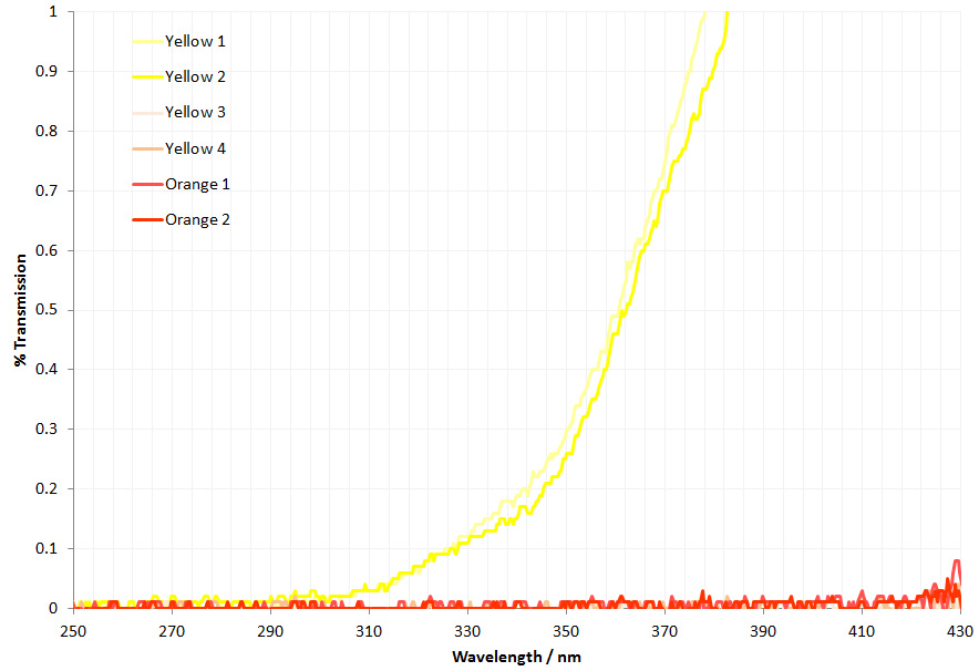
Short wavelength filter transmission

The light yellow filters (Yellow 1 and 2) start letting some UV in at around 300nm and then transmission gradually rises from there. However the darker yellow and orange filters are effectively blocking all the UV light from 400nm to 250nm (less than 0.05% transmission). As the goal is to block the UV while still retaining usability the darker yellow filters are the best trade off between UV blocking and visible transmission, and these will be the ones I use in the binocular head for the UV microscope. It should be emphasised though, that these filters do not obviate the need for UV protective eyewear, they just reduce the risk of damage when using the device while enabling it still be to be used like a normal microscope. I shall still determine the light coming through the eyepieces spectroscopically in the final build.

This UV microscope build has been a really interesting scientific challenge, teaching me more about optics (and microscopes) than I thought there was to know. All the replacement UV fused silica components are now ordered so hopefully in early 2021 I’ll be able to give an update on how it is working. Thanks for reading, I hope you enjoyed it and if you want to know more about this or my other work, you can reach me here.

UV imaging – Yooperlite

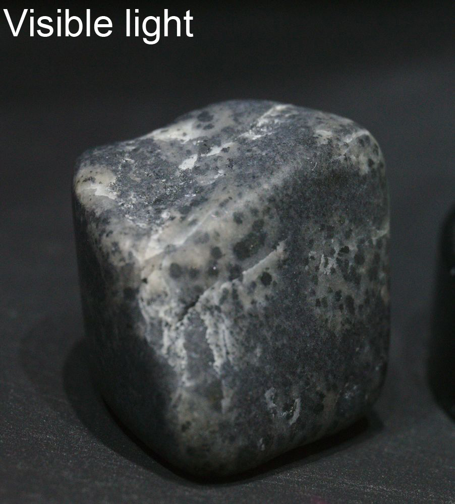
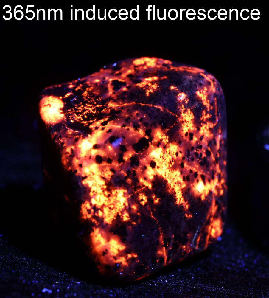
Come on, I bet you were not expecting to see a title saying ‘Yooperlite’. What even is Yooperlite? Well, Yooperlite is a very unassuming looking grey rock, in which is hidden a heart of burning fire. However in order to see its flaming heart requires a mystical light that you can’t see. Ok, enough of that and back to the science. Yooperlite is a a Syenite rock which is rich in fluorescent sodalite, and is found in Michigan. While it looks grey in visible light, when illuminated with long wavelength UV parts of it shines yellow and orange, as shown below.

Yooperlite UV induced visible light fluorescence

Just on case you were wondering, the rock doesn’t look quite as interesting when imaged using normal visible light.

Yooperlite imaged under normal visible light

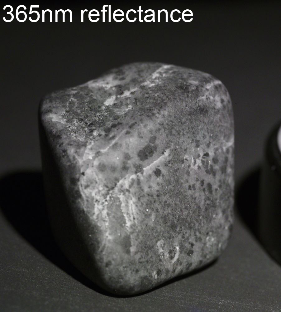
Indeed, it is equally uninspiring when viewed using UV reflectance imaging.

Yooperlite viewed using UV reflectance imaging at 365nm

It really does shine with a fire when illuminated with a UV source. This type of UV induced visible light fluorescence is not uncommon in minerals, with many of them glowing with different visible wavelengths under UV light, however Yooperlite is extremely bright and pretty to look at.

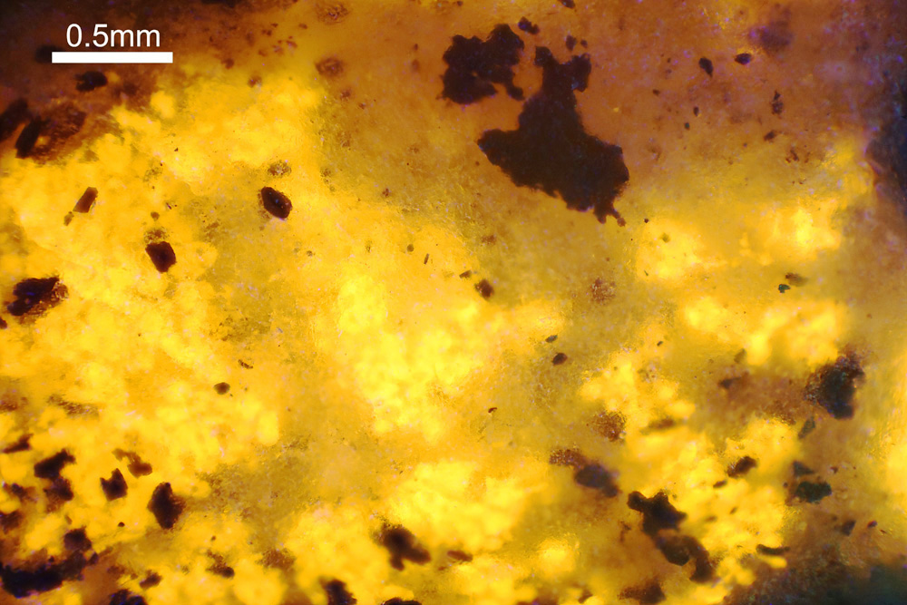
The images above were taken with a macro lens on a normal camera. However, once you realise what needs to be done to carry out this type of imaging, it can also be applied to microscopy. The image below was taken using an Olympus BHM reflectance microscope using a 5x objective, as a stack of about 20 images.

5x magnification image of Yooperlite

Under the microscope, the Yooperlite material looks truly 3d, looking as if there is a fire within underneath a layer of ice.

UV induced visible light fluorescence photography is an interesting and powerful photographic technique, used in a wide range of research fields, from dermatology and forensics, to art conservation, biology and microscopy. As it uses a standard visible light camera and lenses which transmit visible light, it does not need some of the specialist equipment required for UV reflectance photography. However there are still a few things which need to be done to make it work. The light source needs to be filtered to let only UV light through to the subject (I used a Baader U filter on a 365nm torch), and the camera lens needs a filter which blocks UV from reaching the sensor. ‘Ah’, I hear you say, ‘my camera has a filter on the sensor which blocks UV, so I don’t need an additional filter’. Well, yes and no. Normal visible light cameras do have a UV blocking filter, but not all of them block all the UV, so additional UV blocking filtration is also needed on the lens in that case. it is also good practise to use one to eliminate the chance of elements inside the lens fluorescing on UV exposure. I used a 420nm long pass filter which had low inherent fluorescence, so did not give an additional colour cast from UV exposure. Also, you need to image in the dark to get a true fluorescence photo. Really, really dark. All extraneous visible light needs removing for a true fluorescence image. The Yooperlite fluorescence is so strong though, that even in daylight, if you shine a 365nm UV torch on to it you can see the yellow.

The sample of Yooperlite I used was bought from the Caledonian Rock Shop and is about 2cm across. I used a 365nm torch, with additional filtration from a Baader U filter for filtering the light. The camera was a Canon EOS 5DSR and the lens a Rayfact 105mm f4.5 macro lens, with a 420nm long pass filter on the front. The Yooperlite was placed in a box painted with Semple Black 3.0 paint to effectively removed UV reflection and fluorescence around the rock.

Thanks for reading and if you want to more about this or any other aspect of my work, you can reach me here.
UV Microscopy – designing a UV condenser

I’m a bit of dinosaur when it comes to the idea of ‘modelling’. As an experimentalist, I like build and test and then refine my idea, rather than rely on models. Also I’ve been involved in far too many projects where the term ‘model’ and ‘hypothesis’ get used interchangeably, resulting in huge issues which could have been resolved by just doing a few experiments. However there is no doubt that at times and when used properly, modelling can produce useful insights for projects.

With my UV microscope build I am converting an old Olympus BHB microscope into something I can use for doing transmission microscopy down to and below 300nm. At these wavelengths glass becomes opaque and lenses need to be made from materials such as quartz, UV fused silica, or calcium fluoride. And in a microscope there are a lot of lenses which need to be swapped out (as discussed here).

The condenser lens is positioned just before the sample and focuses the light onto the sample – a rather important role. The standard Abbe condenser on my BHB actually did a good job of letting UVA though (see here), but was blocking the UVB. Not unexpected really, as it is just glass after all. In fact, after being reflected through 90 degrees by the mirror below the stage the light then goes through 4 lenses before reaching the sample – the field iris lens, the auxiliary lens, and then 2 lenses in the Abbe condenser – none of which are suitable for UVB. To try and understand a bit more about the light movement and behaviour in these lenses, it was time to delve into the murky waters of optical lens design software. So it was time to grab a fresh cup of extra strong coffee and jump in…..

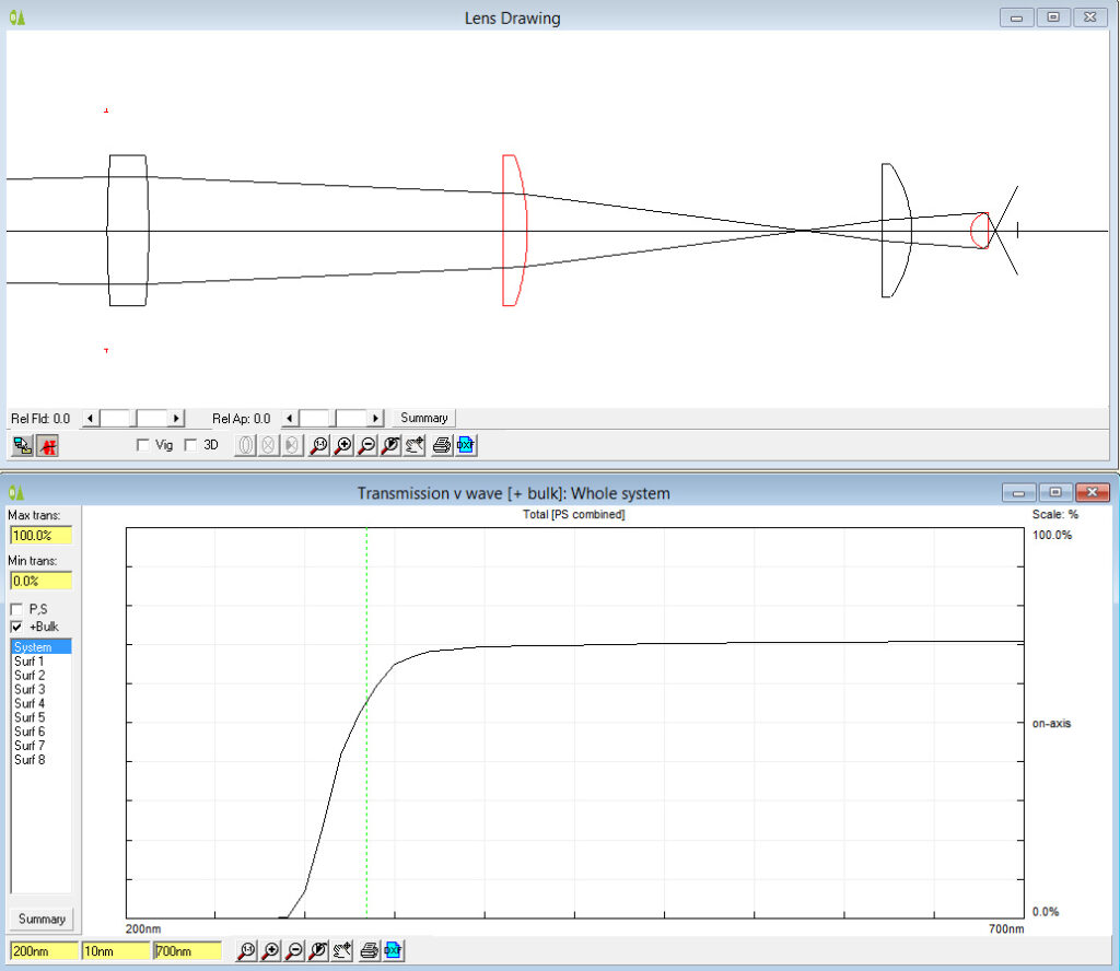
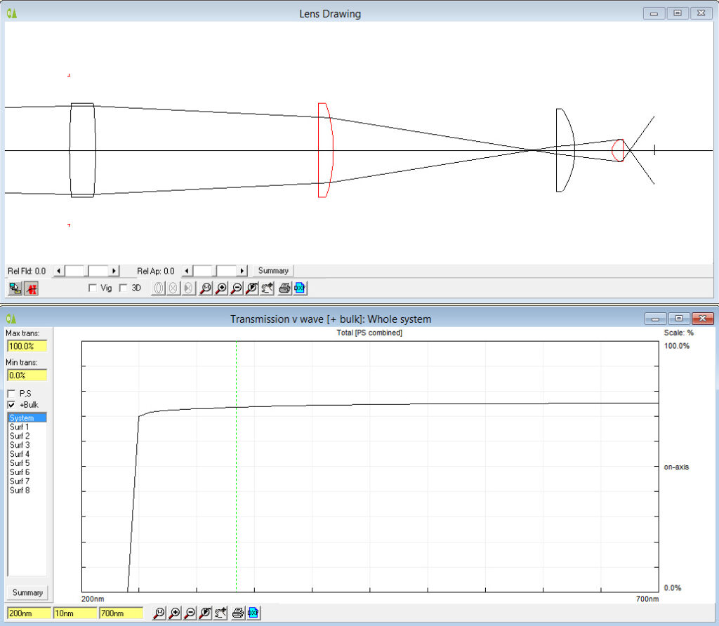
As a novice in this area, I thought I’d try a free piece of software which had some online tutorials – WinLens3D. The first thing to try was to produce a model of the 4 lenses below the stage. Unfortunately one of the lenses in the condenser is an odd shape, so I had to make an assumption for that one that I’d treat it like a half ball lens (a hemisphere). Creating a model with 4 lenses, gave the following.

4 lens stack using BK7 glass as the lens material

Moving from left to right, the 4 lenses in the stack are the field iris lens, the auxiliary lens, and then the 2 lenses from the condenser. This is a rough model, based on some of my measurements, so will not be 100% accurate. The good thing about this type of modelling software, is that in addition to looking at how the light moves through the lenses, the optical properties of the materials can be used to calculate a theoretical transmission spectra for the system, and this is shown in the graph in the image above. Assuming they are made from BK7 (a common glass for lenses) transmission starts to drop at 400nm, before reaching essentially zero at 300nm and below. With this you can see why normal glass is no good for UVB imaging. However with the model, you can change the materials the lenses are made from and see what effect that has. Changing from BK7 glass to UV fused silica gives the following.

4 lens stack using UV fused silica as the lens material

Changing to UV fused silica alters the light movement through the lenses slightly – as expected as the actual focal lengths of a specific lens design will change with refractive index of the material it is made from. However the biggest difference is in the transmission spectra. UV fused silica has great UV transmission, and as you can see the predicted transmission plot now shows a pretty much flat transmission curve down to 250nm, well into the UVB region. The software then does something a bit odd though – the transmission plot drops straight to zero at 240nm. I actually think this is a quirk in the software, as the fused silica should be good down to around 220nm. I suspect the data for the silica just stops at 250nm. Overall, moving to UV fused silica looks good – the model seems to predict good transmission, and the change from glass while slightly altering the light path should not make it unusable.

What to do about the condenser? I have a vintage Zeiss quartz microscope condenser currently waiting for me in the US to be collected the next time I visit, but Covid has put all those plans on hold for now. In the mean time, is it possible to modify an existing condenser by replacing the glass elements with UV fused silica ones? Using an existing condenser is the preferred option, otherwise it’d need custom machining work in addition to new lens, and the costs would rise very quickly. Taking a spare condenser apart presented the first challenge. One of the lenses was secured by a ring that had been glued in place in the factory. Having tried polar solvents, non polar solvents, heat, cold and various other methods to free it off nothing worked, and I resorted to the tried and tested approach of ‘hit it with something hard’. I got the lens out but not in any form which was useful. It did however leave me with the metal condenser housing which could be reused. The lens itself was 35mm diameter, which is an odd size for my supplier to source a replacement. To fix this I bought a 30mm filter ring and glued it in place where the old lens was. This allows the use of 30mm diameter lenses, which are much more common. I currently have one on order, and will update when it arrives.

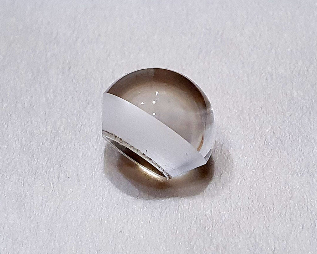
The top part of the condenser has a very odd shaped lens in it. It looks to be based on a ball lens, which then has a section sliced from it, and a chamfer ground into it as can be seen below.

Olympus Abbe condenser lens

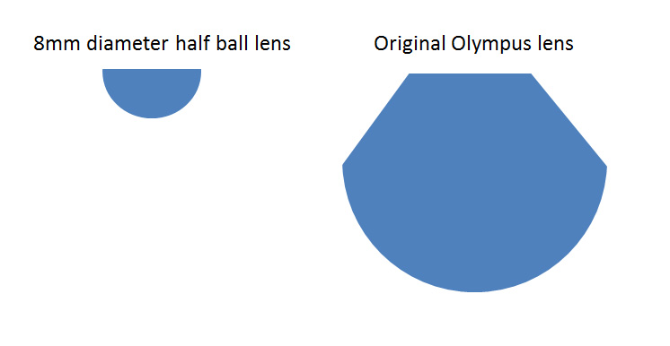
This is a not a common shape, and after trying multiple suppliers have currently given up on trying to find someone who can make this in UV fused silica. If I win the lottery, I’ll come back to getting one custom made, but it’ll have to wait for now. Looking at the shape though, it got me wondering whether a half ball lens would work. In fact it was a half ball lens that I used in the WinLens3D modelling above, and it looked like it should do the job. Half ball lenses are a bit more common, although I was looking for a large diameter one, which is much rarer. In the end I found an 8mm diameter UV fused silica one at Knight Optical here in the UK. This was much smaller than lens it would replace, but was worth getting to test the idea. The two lenses are shown below, highlighting the differences in shape.

Comparison of the half ball lens with the original one

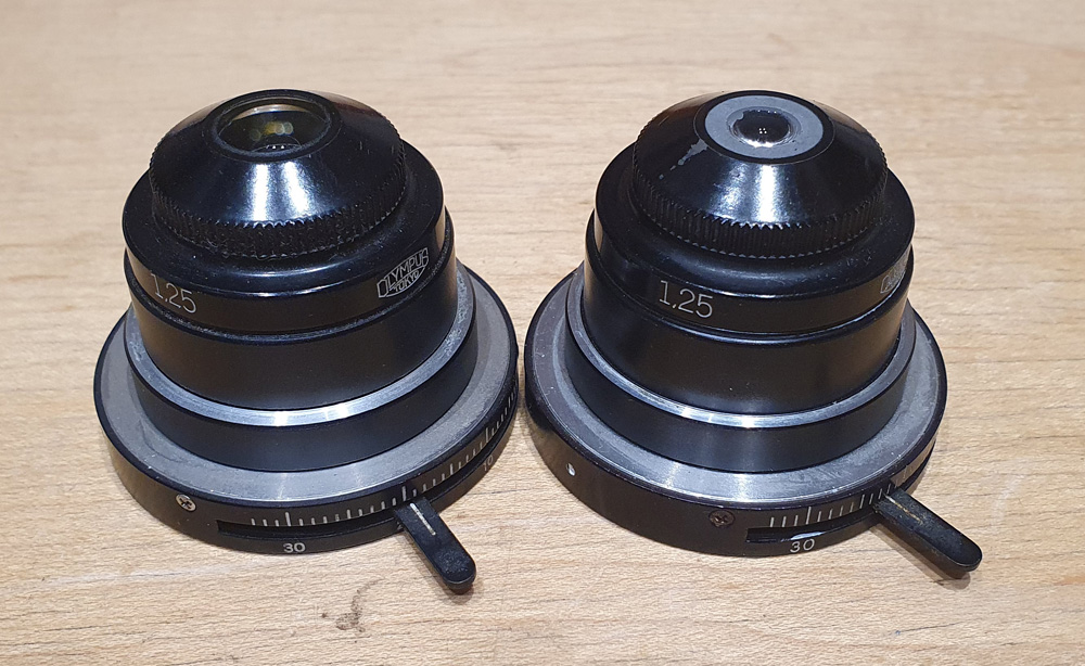
The smaller lens left me with a bit of a problem – how to mount it in the condenser? The original lens was held in place with a screw ring, but the new lens was much too small for that. I resorted to my old friend JB Weld, which is a 2 part epoxy adhesive used for fixing anything as far as I can tell. The good thing is that it is opaque as well, and I just glued the lens in place using the JB weld to fill the gap around the lens. The photo below shows the original (left) and the modified condenser (right), and you can see how small the UV fused silica half ball lens looks compared to the original one.

Original and modified condensers

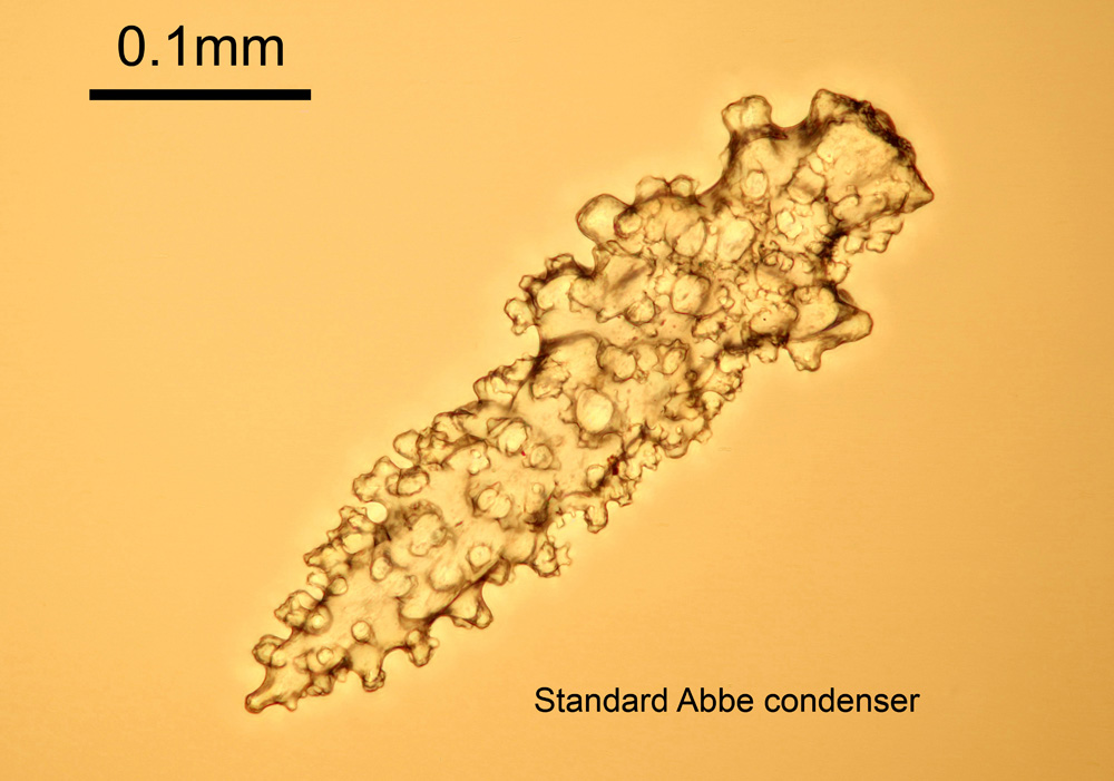
Making one of these is all well and good, but if it cannot illuminate a sample it really is not going to be a good condenser. As a quick test I imaged a sample slide of Gorgonian sea fan spicules (from Diatom Lab). These guys make high quality microscope slides great for microscopy testing and imaging, and I’d recommend checking them out if you want slides for imaging. The objective was an Olympus 20x SPlan, and the lighting a tungsten bulb in the microscope. This is a visible light image taken with a normal camera, just to test to see if the condenser would work. The warm cast to the image comes from the tungsten bulb. Images were collected as a stack of about 15 shots and processed in Zerene stacker. UV testing will come later. Firstly one of the spicules taken using the original unmodified Abbe condenser.

Image with the standard Abbe condenser

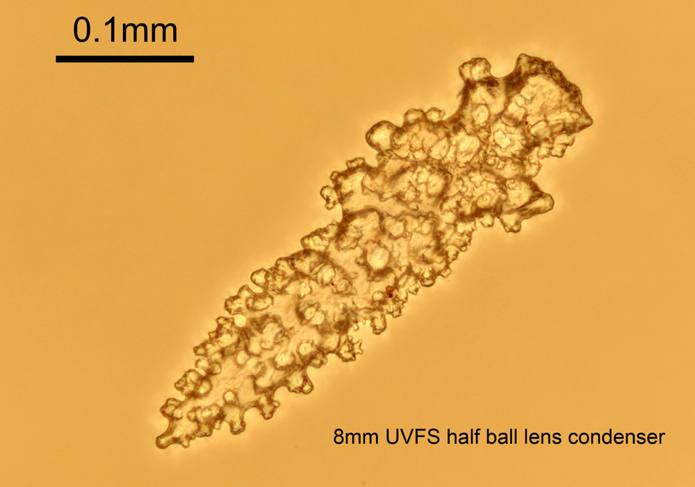
Now an image where the standard Abbe condenser was replaced with just a single 8mm UV fused silica half ball lens.

Image with the 8mm UV fused silica half ball lens

While slightly lower contrast than the standard Abbe condenser the 8mm UV fused silica half ball lens was still able to provide good lighting for an image of the spicule. Success. Also the condenser with the 8mm half ball lens is currently missing the second lens which is present in the standard one, so hopefully image quality should improve further with both lenses in place.

There are some drawbacks to using such a small lens. Sample size is limited, along with the choice of objectives. I need to use 10x or higher magnification objectives with it, but as my UVB capable objectives are 10x and above this is not a problem. The light leaving the half ball lens is highly convergent, so condenser position is crucial to getting good lighting. How this will work in UV remains to be seen as focal length will be different to that in visible light and may leave me with slightly less working distance to play with. The image with the half ball lens was slightly darker than with the standard condenser leading to longer image acquisition times (approximately one stop difference).

Where does this leave me? The conversion of a microscope to being able to do UVB imaging is a complex job, certainly more complex than I originally thought it was going to be. As such it takes time and testing. Modelling of the optical properties of the lenses has proved useful, and testing so far is looking good. I’ve been able to modify an existing condenser to install a lens which has great UV transmission characteristics and use it to create good quality microscope images. More work to be done for sure, but the UV BHB is coming along, and I am now a step closer to completion. If you want to know more about this or any other aspect of my work, you can reach me here.
Addendum – after writing this article, I’ve been able to source some larger diameter half ball UV lenses (12mm as opposed to 8mm) and they have been sourced for future testing.

UV Microscopy – All aboard the optical train

When doing normal visible light photography, the question of whether the wavelengths you’re interested in capturing can even reach the camera, tends not to come up. Lenses are transparent to visible light, and our eyes and camera sensors are sensitive to it, so we can see just what we are going to be imaging. Simple. However with UV photography that is not always the case. Normal camera lenses block varying amounts of UV and if you want to image the UVB region, you need to delve into the realm of dedicated UV optics without normal glass. Even with those considerations, with UV photography once you have a suitable lens and filter, and a modified camera you are good to go. The concept of doing UV microscopy though, takes the things you need to consider for photography and amps everything up to 11. Today I’ll bring some of the work that I’ve been doing to build a UV microscope together and see what I have still got to do.

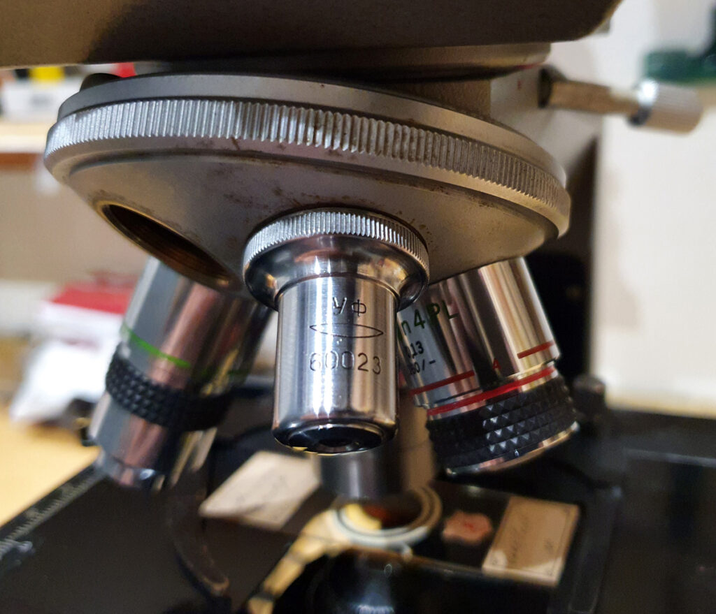
The optical train for a microscope is quite complex. In my microscope, starting with the light source, the light then goes through between 1 and 5 lenses, and bounces off a mirror, all within the body of the scope before going through the condenser. Then we have the slide and coverslip with the sample. After that we have the objective lens. Above the objective lens we have the head with the eyepieces, which also contains the photoeyepiece. And it is only all of this that we have the camera. Some of these I have discussed before, and are linked in the description above. I’ll now go through some more recent work looking at whether the internal lenses, mirrors and windows within the microscope are suitable for UV, and if not how to address that.

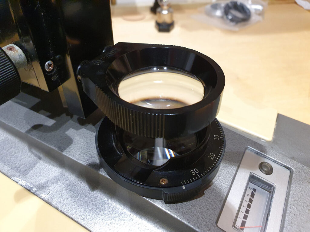
Within the body of my BHB microscope there are a set of lenses and a mirror that the incoming light has to traverse before it even reaches the condenser. These are to focus and direct the light so it can reach the sample with enough intensity. 3 of the lenses aren’t absolutely necessary for the UV imaging, as the xenon and mercury xenon lamps I have have some degree of internal focusing. However this still leaves 2 lenses, and mirror which are necessary. The two lenses can be seen in the image below.

Two lenses for focusing the light

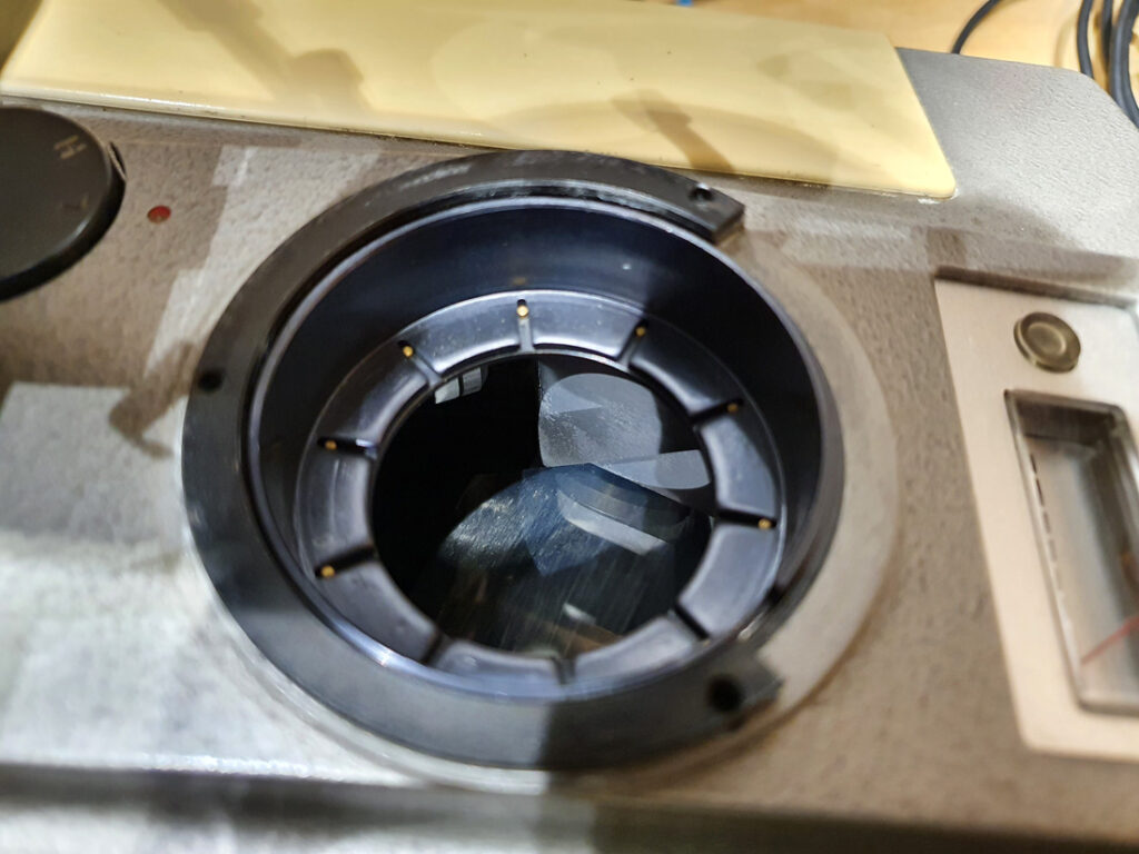
The top lens above is the Auxiliary lens, and this isn’t always needed depending on the magnification you are using. Below that with the numbered scale is the Field Iris lens. Below the Field Iris is a mirror which bounces the light from horizontal to vertical. With the Field Iris lens removed, you can just about see the mirror underneath.

Mirror beneath the Field Iris lens

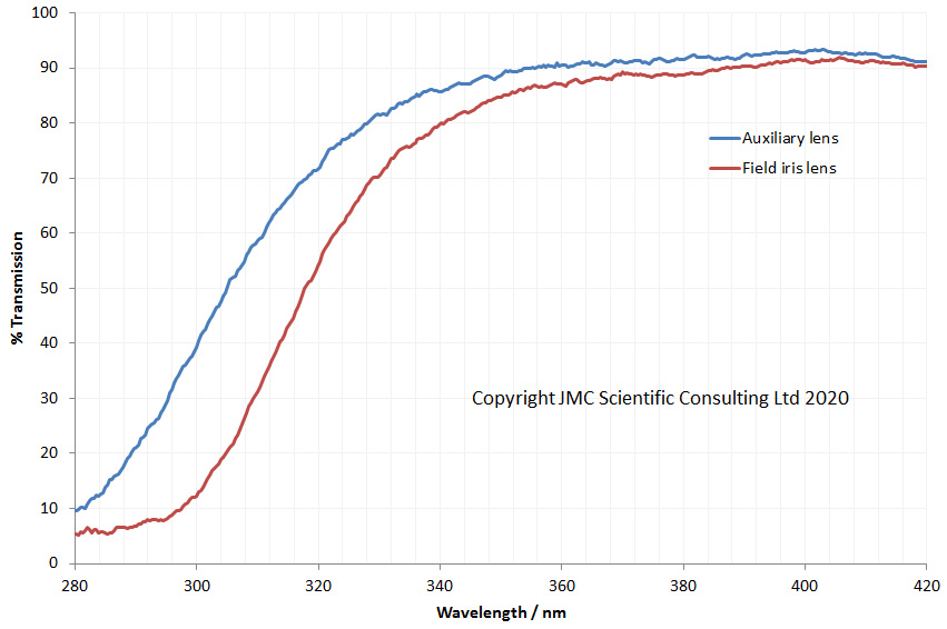
In order for the microscope to be usable for UV imaging, the lenses need to be able to transmit the UV, and mirror needs to be able to reflect it. I removed both lenses and measured their UV transmission using my lens transmission testing rig, and got the following.

Auxiliary and Field Iris lens transmission

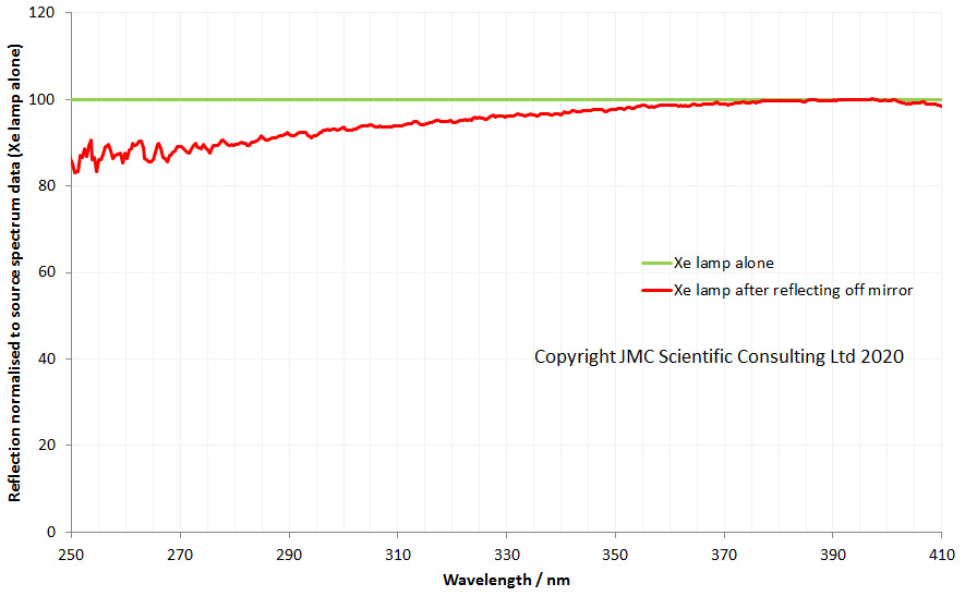
Both lenses looks like they’d be OK for 365nm imaging, but at the shorter UV wavelengths the transmission drops quickly. This makes sense as they are glass lenses, and normal glass absorbs UVB. So they’d be no good for UVB imaging. Determining whether the mirror would be suitable for UVB was a bit more problematic. I do not have a setup for accurately measuring specular reflection from shiny surfaces, and I didn’t want to remove the mirror unless absolutely necessary, as they can be annoying to realign. This meant trying to test it in-situ. To do this I used a Xe lamp. I measured the spectrum of the lamp by itself. Then shone the lamp off the mirror and measured the spectra again. I then normalised these for max irradiance (which occurred at about 400nm) and calculated how much light was reflected from the mirror vs the light output from the lamp alone for between 250nm and 410nm, and got the following.

Mirror reflection from 250nm to 410nm

The mirror reflection shows no major dips down to 250nm indicating good reflection in the UVB. This is not a perfect test, as I am assuming that 100% of the light is reflected at 400nm. However it is good enough for seeing whether there are any big dips in the reflection spectra. The next job was determining focal lengths for the lenses. The Auxillary lens was 40mm diameter, planoconvex and about 7cm focal length. The Field Iris lens was 40mm diameter, biconvex and about 13.5cm focal length. For replacement UV suitable lenses, I’ve gone through Laser2000, who have good range of lenses in different sizes and focal lengths and went with a 7cm planoconvex, and 15cm biconvex. For the biconvex the available focal lengths were 12cm and 15cm, however as the wavelength decreases the focal length does too for these simple lenses, so the 15cm is nearer to the original in the UV. These lenses should enable good transmission of UVB to the condenser. Will this prove to be the right choice – I shall see when then lenses arrive. Watch this space…

The next thing to consider what happens to the light between the objective lens and the camera. On the Olympus BHB there is a binocular head which fits on top of the microscope which allows the user to view the sample. This can also be fitted with a third vertical tube (making it a trinocular) which enables a camera to be fitted. The head however also has some optics in it – a thick window at the base, and a beamsplitting prism to enable the light to be split between the eyepieces and the photoeyepiece for the camera. Of course, every piece of the glass in the optical train has to be assessed for suitability when thinking about UV imaging. How do these components impact UV transmission? Thankfully the BHB head is straight forward to take apart (I love old mechanical designs). Doing so reveals a thick window at the base of the head and the prism beamsplitter assembly, as shown below.

Thick window from BHB head
Beamsplitter assembly from BHB head

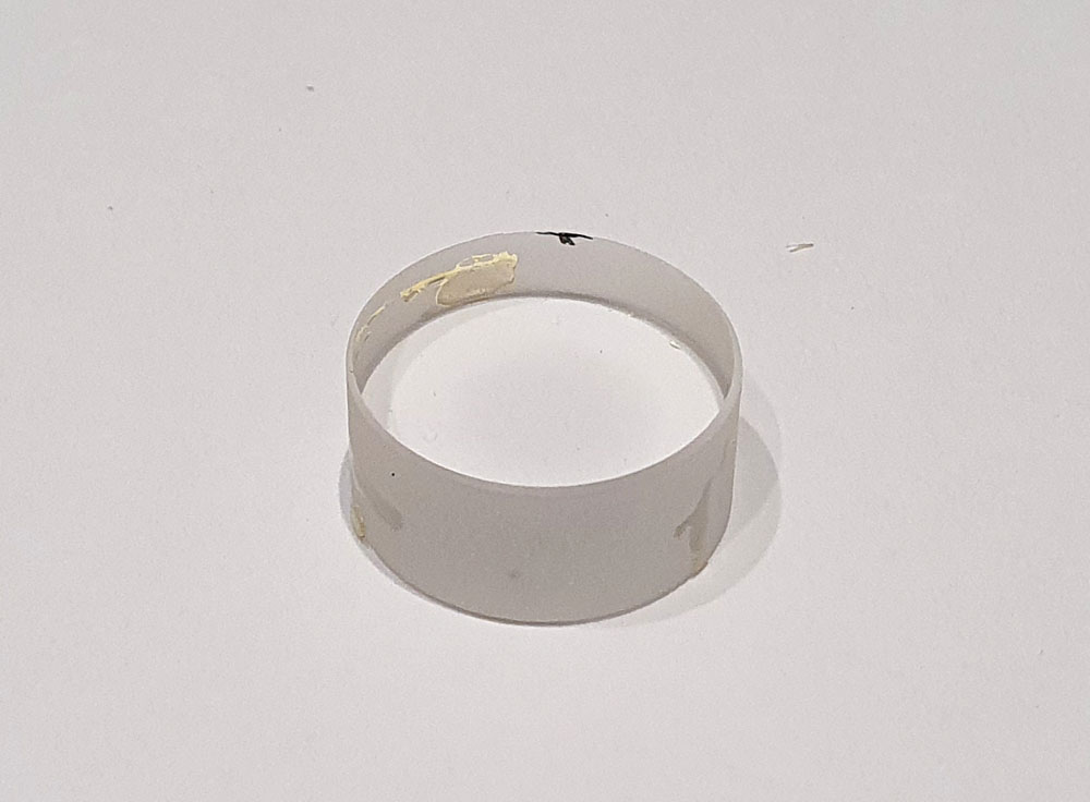
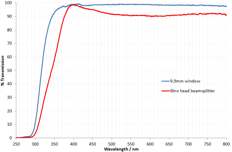
The window is thick, very thick. The size is 20.9mm diameter and 9.9mm thick, but it does look to just be a window and not a lens. It also looks to be a simple single element. The beamsplitter is more complicated. In the position shown in the image above the light is sent to both the viewing eyepieces, and the photoeyepiece. While not obvious in the photo, this requires two prisms – one on top of the each other – and there is a glued interface as well, making it quite complicated. There is no path to the photoeyepiece without going through this prism arrangement. The transmission spectra for these two components are shown below.

Transmission spectra through the BHB head optics

Both the window and the beamsplitter show good transmission at 365nm, but the transmission does drop quickly as the wavelength gets smaller, and is essentially zero by 300nm. For imaging at and below 300nm both of these will block all the UV and be opaque. This could be a tricky one to fix – if I want to use the head for UVB, so I can view the sample before taking the photo, I’ll need to figure out a way of getting the UV through these components. I can just use a vertical monocular tube for the photos, as that has no optics in it, so there is another approach, but I’d like to keep the optical eyepieces if possible. More thought needed here, especially with regards to making the use of eyepieces with UV light sources safe…… After more thought (and more coffee) I shall take some measurements and source suitable components to test.

Just over 6 months ago now I started my journey into microscopy, and it has so far proved fascinating and challenging in equal measures. Setting myself the challenge of making a UV microscope able to be used down below 300nm have really made my life difficult. But then science is often difficult, and a challenge is not something that should be shied away from. Being able to image in UVB and UVA will be useful for my sunscreen research and for imaging sunscreen formulation structure. If I were to try and have a UVB suitable microscope built, I doubt I’d get much if any change from 100,000USD so until I win the lottery is a bit outside my R&D budget. In fact a couple of the objective lenses alone if bought new would cost more than I have spent on my entire project to date, so a self build is the only option. I’m not there yet, but am gradually working through the issues and will update as and when I have more results. If you’re interested in this or any other aspect of my work, I can be reached here.

Microscopy – reflectance imaging of a modified camera sensor

It’s always the same when I attempt some DIY – I start out with a plan, and a pile of bits, and I invariably end up with parts left over at the end, and a nagging question about where they should have gone. It’s been a little like that with Project Beater, my microscope build. As I’ve gone along buying spare parts for it and bits of donor equipment, I’ve ended up with some stuff which I wasn’t really sure what to do with. A couple of weeks ago it dawned on me that I almost had enough parts to make a reflection microscope, to go along with the transmission setup I already had. So back on eBay (for a few more missing parts) and that is precisely what I did….

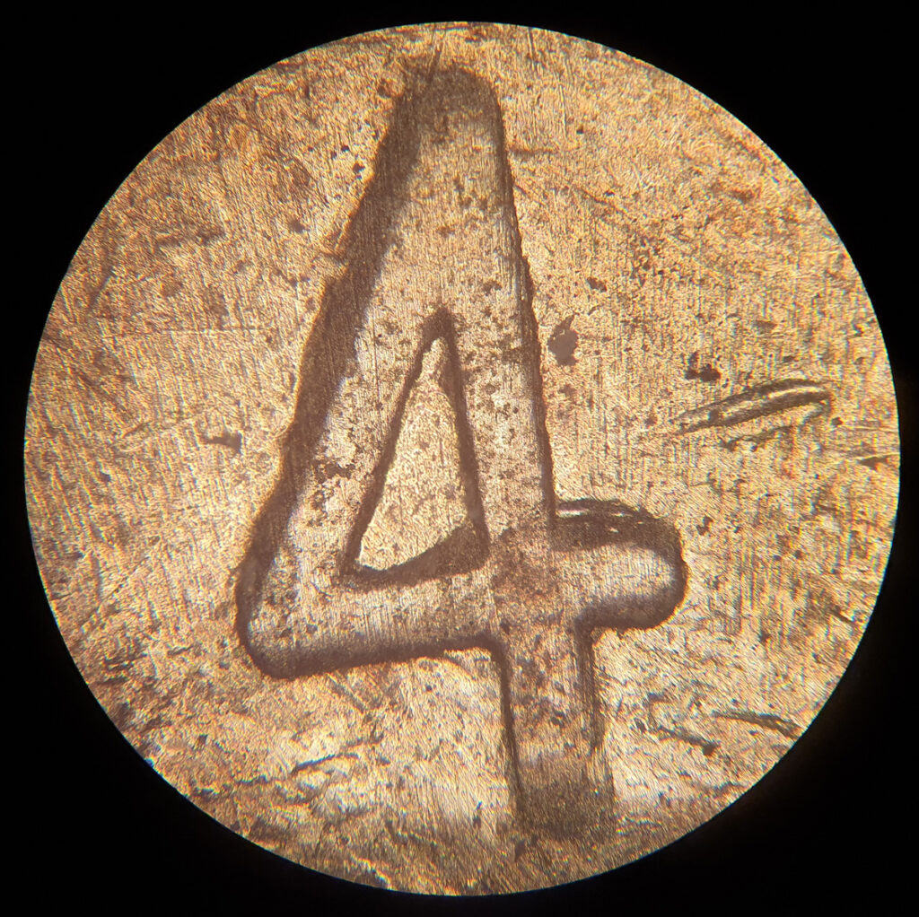
Reflection microscopy relies on top illumination and is used for non-transparent samples. It’s often used for looking at gems, metals, feathers, fabrics, etc etc. Before I show you a picture of the setup though, here’s one of the sample pictures I took to try it out once it was assembled. I’ll leave you to figure it out what it is for now, and come back to it later…..

Can you tell what it is yet?

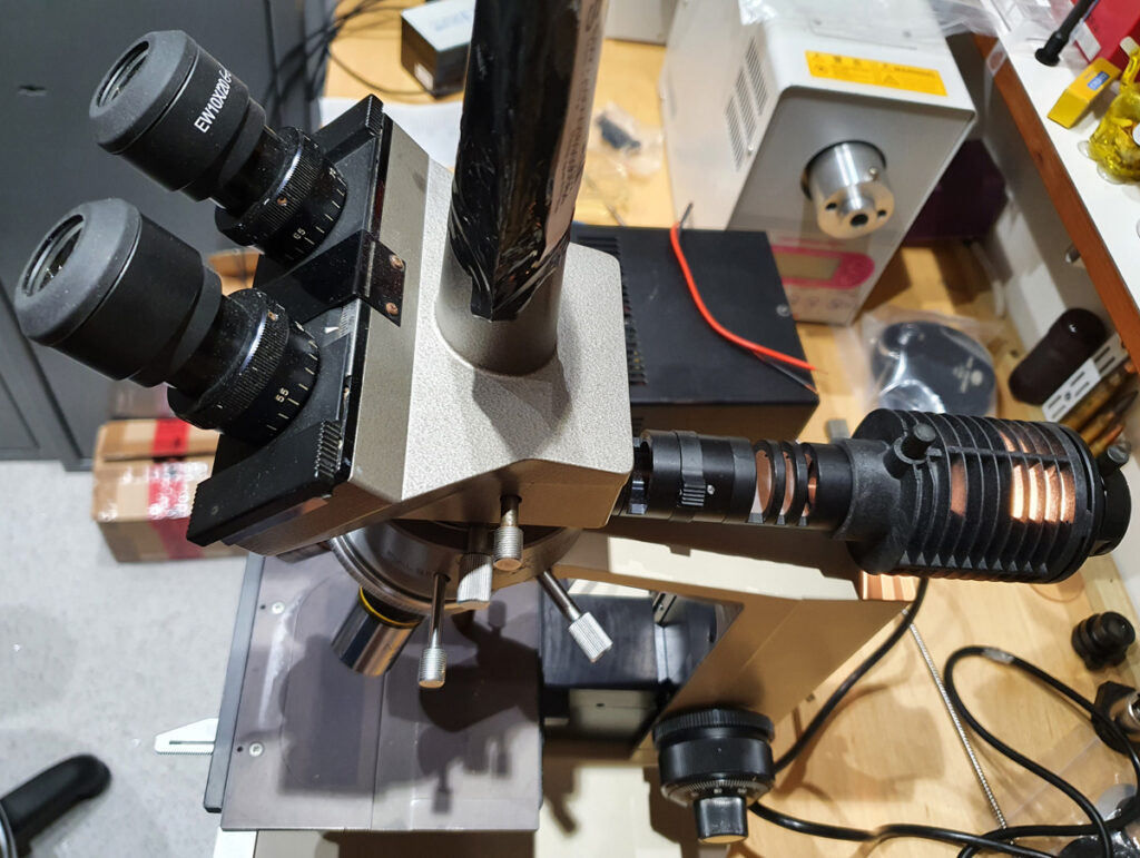
My setup was based around an Olympus BHM chassis, a reflected light setup placed on top of the microscope, and then a normal or trinocular head on top of that (depending on whether or not I want to take photos). The objectives are old Olympus Neo ones, designed specifically for this type of ‘top down’ imaging as they have a channel around the lens to allow the light to be shone down there rather than through the objective itself. Here’s what it looks like from above.

Olympus BHM reflection microscope setup

The original light source is a 15W 6V Tungsten filament bulb, but these are both expensive and difficult to source now, and give a very warm colour cast to the image, so instead I just used a 10W cool white LED source I built previously. This gives out plenty of light, and with very little colour cast. Plus it has the added benefit of being virtually immortal.

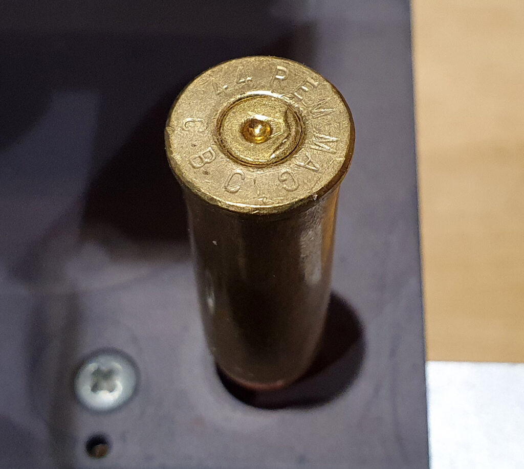
So, back to the test object. Did you figure out what it is? Here it is in its entirety.

44 Remington Magnum inert round

The image was one of the ‘4’s from an inert 44 Remington Magnum round, taken with a 10x Neo objective, imaged using a camera phone through the eyepiece (overall magnification 100x).

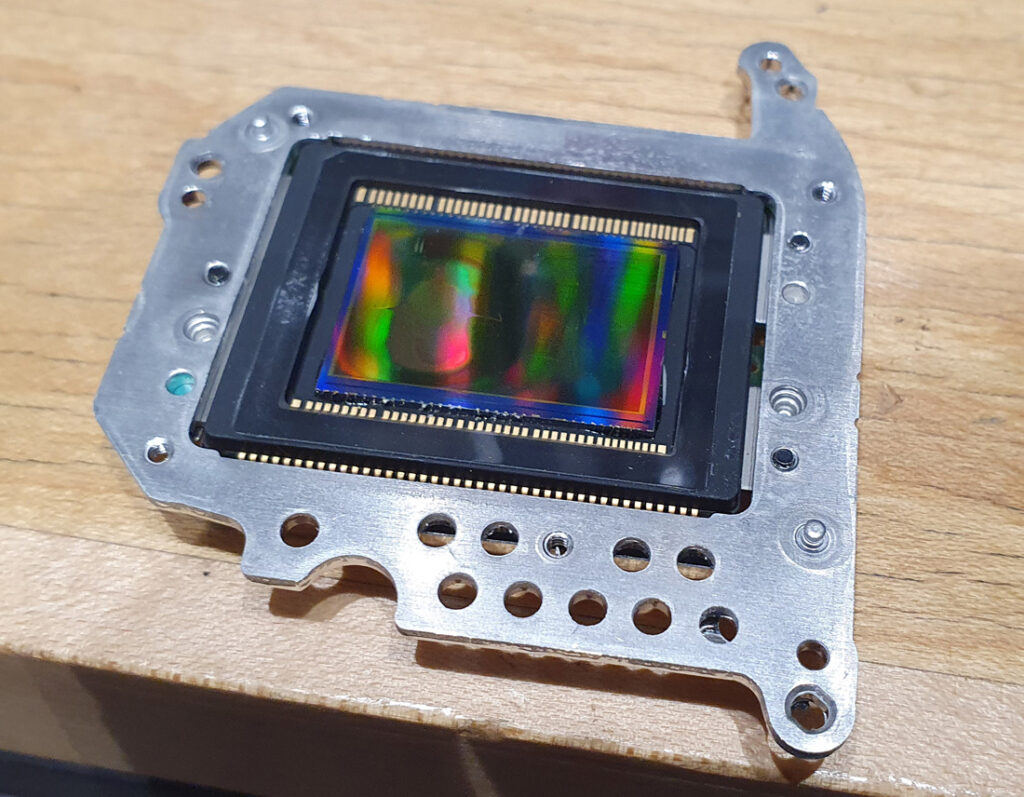
While looking at old brass is one use for these types of microscopes, I did have a different use in mind when I built it. I have some monochrome converted cameras for my UV work, and for a while I’ve been wanting some nice pictures of a camera sensor to show what it looks like as a result of the conversion. So I got a damaged sensor which had been partially converted to monochrome, and as a result had regions which were left untouched, regions which had the microlenses removed, and other parts which had had the microlenses and Bayer filter removed. Here it is (with the area where the Bayer filter has been removed to the left of centre);

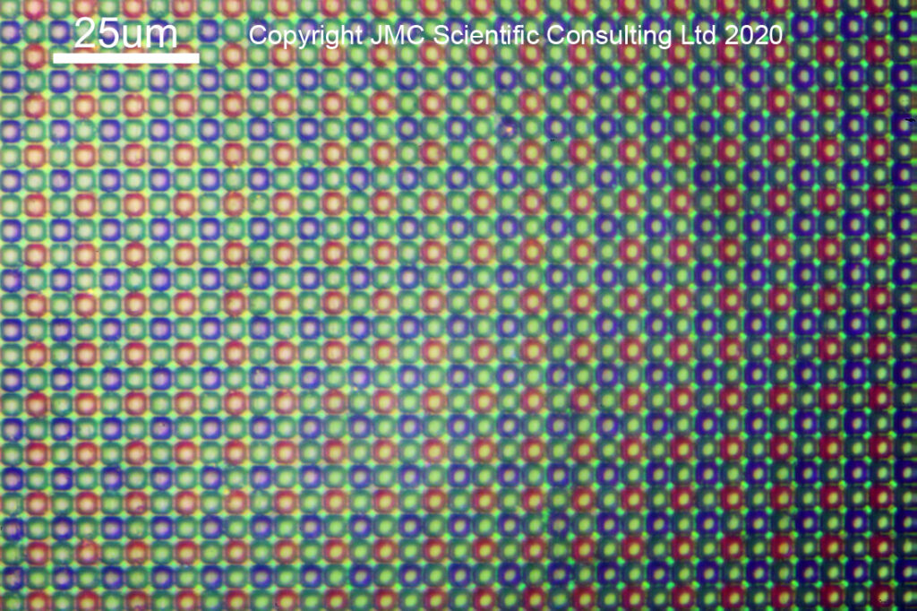
What does a camera sensor look like in its normal form? Here we have a reflection image of the sensor from part of it which hadn’t had anything removed, taken with a 40x Neo objective.

Camera sensor including microlenses and Bayer filter

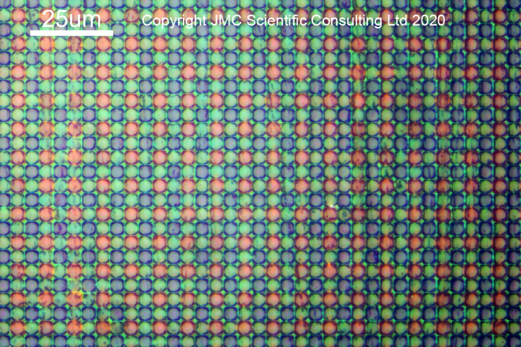
You can see the very neat arrangement of red, green and blue filtered pixels (2 green to 1 red and 1 blue). On top of each coloured region is a microlens. This focuses the incoming light through the coloured filter and into the sensor to be collected. In a conversion to monochrome, these microlenses and the Bayer filter are removed, leaving the bare sensor behind. Here you can see what it looks like as the microlenses start to be removed.

Microlenses partly removed.

And then, with the microlenses fully removed.

Microlenses removed

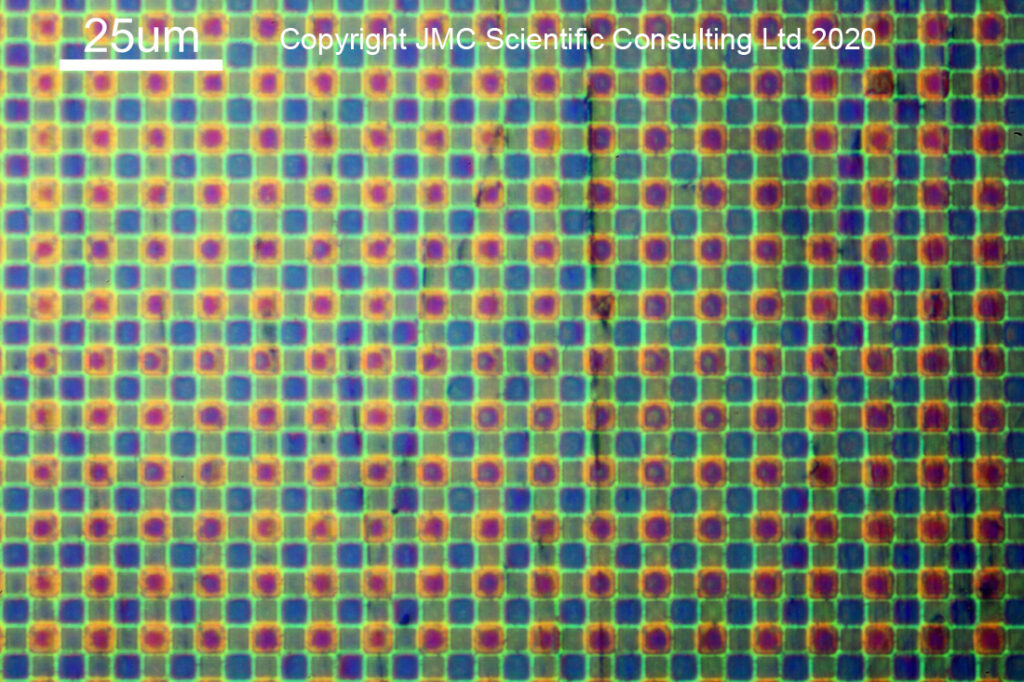
With the microlenses removed, you can now see the coloured squares of the Bayer filter. Oddly enough the green ones look smaller than the red and blue ones, and I’m not quite sure why that would be the case. With the monochrome conversion, this coloured filter layer is also removed, and the bare sensor is revealed.

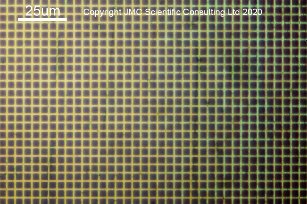
Monochrome converted region

With the monochrome conversion, all trace of the coloured Bayer filter is now gone. It also reveals why the microlenses play an important role in the sensor design. The darker squares are, I believe, the sensitive parts of the pixels. The microlenses gather light from a larger area than the pixel itself, and focus it down into the sensor to be collected. Sensor architecture also plays a significant role in their effectiveness at this task, but that is a story for another day…

The sensor I had for imaging was damaged, and quite fascinating to look at under the microscope. I found a region where something sharp had been dragged across it, scraping away the microlenses and Bayer filter, revealing the sensor underneath. It enables the different regions to be captured in one image – raw, untouched, sensor with microlenses, microlenses partly removed, microlenses completely removed from the Bayer filter, and bare sensor with the Bayer filter removed – as shown in the image below taken with a 20x Neo objective.

Scratched surface of the camera sensor

As a quick note for the microscopists amongst you, I used bright field imaging for these images. With this the light is directed down the objective optics, before being reflected back up along the same path. This reduces the image contrast somewhat. The Neo objectives have a path around the edge of the optics for the light to travel, ending up with an image which I suppose is a bit like a dark field transmission image, but I did not use there here as the bright field illumination photos looked nicer.

When you start on a new adventure, it isn’t always clear where you are going to end up. When started with microscopy about 6 months ago, I’d assumed I would be doing transmission imaging. By learning as I go along, I’ve now ended up with a reflection microscope, which has allowed me to visualise what I had theorised about when writing about monochrome camera conversions and UV imaging. As scientists we should always be open to letting the work guide us, in addition to just ‘running the experiment’.

Thank you for reading, and if you’d like to know more about this or any of my other areas of work, I can be reached here.

UV leakage through stock camera sensor filters

When it comes to UV fluorescence photography, setting up of the lighting, subject and imaging system are key to getting good results. An important part of this is knowing how your equipment works, along with its limitations. Today I’d like to share the results of testing which show how UV is leaking through the internal filter stacks of some of my cameras, and how that effect can be rectified.

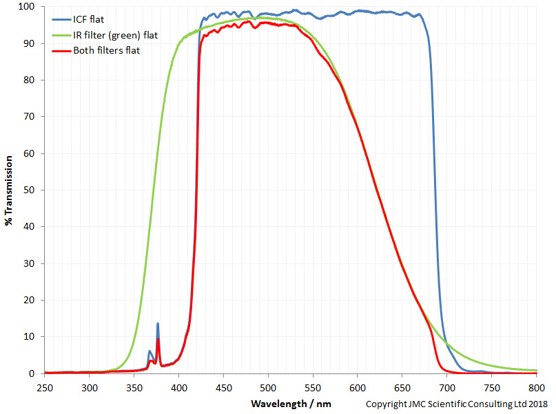
This all came about when I first measured the transmission spectra of the filters which were removed from a camera I was having converted to multispectral imaging (a Canon EOS 5DSR). The filter stack consisted of a green IR blocking filter, and a dichroic ICF filter which is supposed to block UV and IR. However when I measured the transmission through the two filters I got the following spectra.

Transmission through Canon EOS 5DSR internal filters

What was worrying was the ICF filter had a significant UV transmission peak at around 365nm, which means that UV light can actually reach the sensor in a stock camera (the red line is the combined transmission through both filters). This got me wondering what the end result of this type of leakage would be in a fluorescence image.

Fast forward about a year, and I was doing some fluorescence imaging for an article, which was using UV light to look at the fluorescence of a glass vase, and seeing what the effects of different blocking filters on the camera lens were. A quick guide to the setup. Light source was a Hamamatsu LC8 with a 200W Xe lamp. A Baader U was used on the output of the light source, to make it UV only and remove the small amount of visible and IR light being emitted. Subject was a painted glass vase, placed in a box painted with Semple Black 2.0 paint which I’ve found to be both highly light absorbing and very low fluorescence making it ideal for UV imaging work. Camera was a stock, unmodified Canon EOS 6D with a Rayfact 105mm UV lens. Imaging was done in the dark apart from the UV light source (obviously). All exposures where for the same length of time.

Firstly, the vase imaged with no filtration on the camera lens.

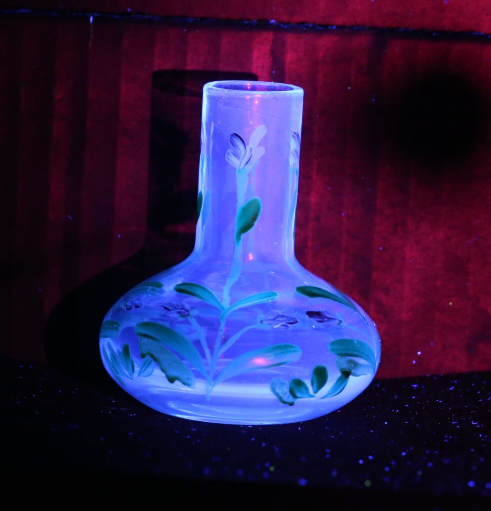
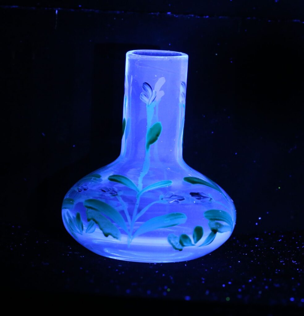
Vase fluorescence under UV light, with no lens filter

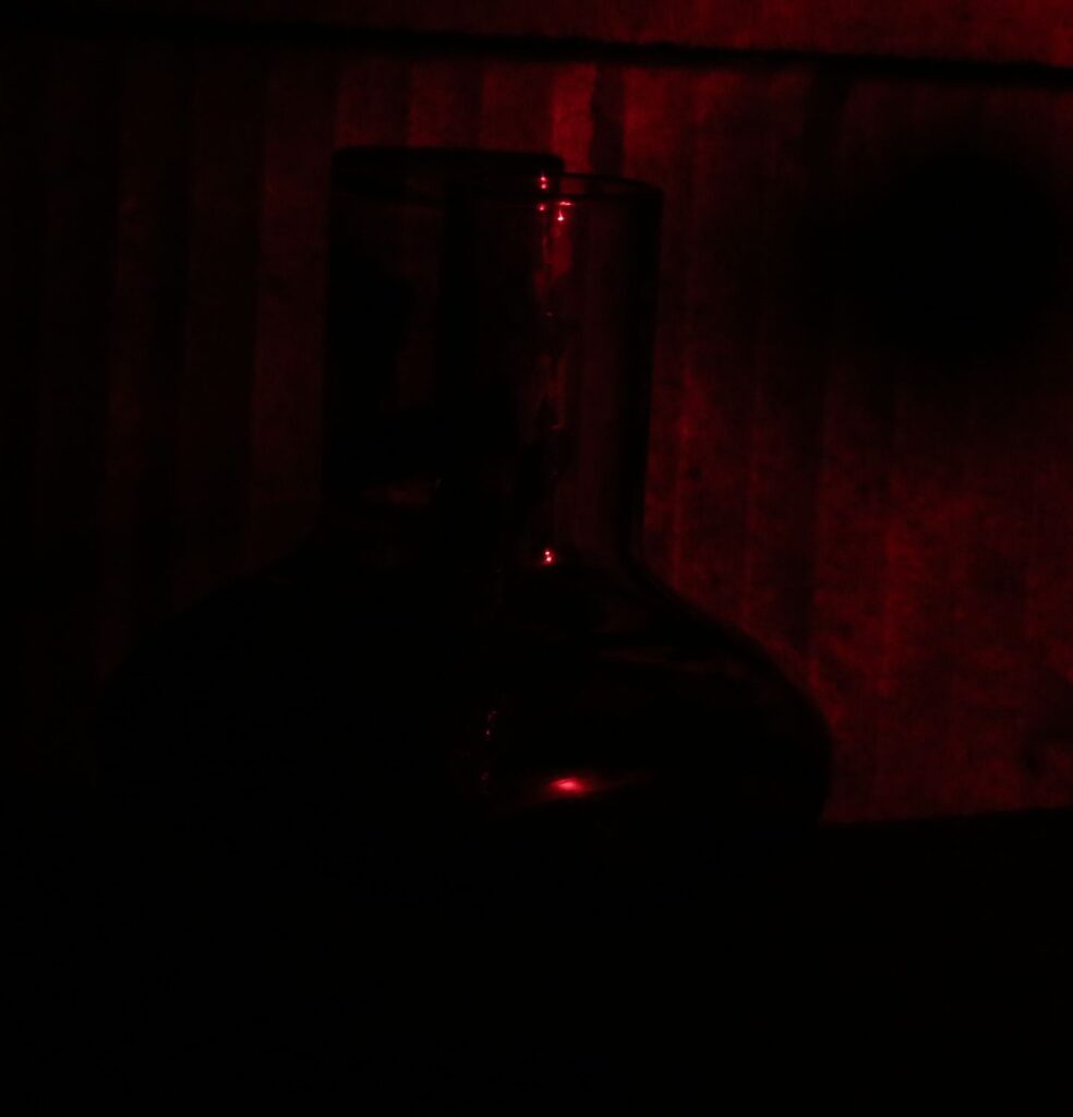
The vase shows the expected blue fluorescence, but there seem to be red areas in the image and they look to be reflection rather than fluorescence based on the parts of the glass they are showing up on. It is also red on some of the black painted cardboard. The ever present dust also shows up with blue fluorescence (damn you, optical brighteners).

The next stage was to add a UV blocking filter to the front of the camera lens. First one was the Schott KV418 which is well known in the UV fluorescence imaging world as having good UV blocking and low inherent fluorescence.

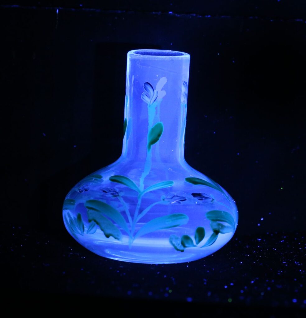
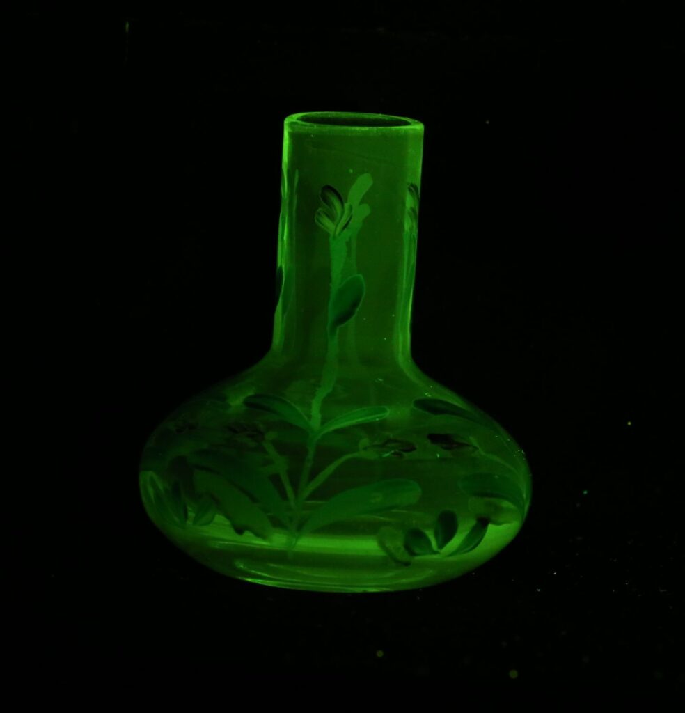
Vase fluorescence under UV light, imaged with a KV418 blocking filter

Adding the Schott KV418 to the front of the camera lens removed the areas which appeared red in the unfiltered image, confirming my suspicions that those areas where to do with UV reflection which was making its way through the stock internal camera filters and hitting the sensor.

As a final confirmation that reflected UV was indeed the cause of the red highlights in the unfiltered image, I removed the Schott KV418 filter and replaced it with a LaLa U filter from UVIROptics. This filter lets UV through, but very effectively blocks visible and IR light, and is a great choice for UV photographers. Doing so, gave this image.

UV image of the vase, using a LaLa U filter

Using the LaLa U filter, the blue fluorescence is now gone (as expected as the filter is blocking the visible light), but the red still remains in the areas shown in the original unfiltered image. It is a little darker as the LaLa U filter is absorbing around half of the UV light, due to its transmission curve. Remember, this is a stock camera with internal filters which are supposed to be blocking UV.

Ok, so it is fairly obvious that the stock Canon EOS 6D filtration is not enough by itself to block reflected UV light with the fluorescence images. Schott KV418 is good at blocking that reflected UV, but, Schott KV418 is no longer widely available (and do you homework on anyone claiming to be selling it – the only legitimate source I know of was ITOS in Germany, and I’m not even sure they have any anymore). However I found that Zeiss T* UV filters also did a good job of blocking the UV and were themselves low fluorescence. This is what the vase looked like when imaged with using a Zeiss T* filter on the camera lens.

Vase fluorescence under UV light, imaged with a Zeiss T* UV blocking filter

As a final image, and why not, here is the vase imaged using a Tiffen 12 yellow filter, as the blocking filter.

Vase fluorescence under UV light, imaged with a Tiffen 12 filter

The Tiffen 12 image doesn’t really add to the story, I just think it looks funky.

So, some comments on the images and the experiment above. The transmission spectra for the filters I have was for a Canon EOS 5DSR, and the photos were taken using a Canon EOS 6D. The cameras were different, and I do not have the filter stack from a 6D to check. I therefore cannot be sure that it would be exactly the same as the 5DSR one. However the images back up the hypothesis that the stock filters are leaking some UV. I used a Rayfact 105mm UV lens for the images. That is a nice sharp macro lens, but has high UV transmission, which emphasizes any UV leakage. I have done some other work with different (normal) camera lenses, and the effect is still visibly, although reduced in intensity. I used a Zeiss T* UV filter for one of the images. Not all UV filters block UV – some are just plain glass. Unfortunately this is an example of where marketing trumps science, and claims are made about products which do not stand up to testing. In the absence of owning a spectrometer, if you shine a UV torch (which has the black looking filter on it to remove visible light) through a UV filter onto white paper, if the UV filter is not blocking the UV light then the paper will fluoresce. If the paper does not fluoresce then the UV filter is blocking the UV light, giving you a rough indication of how good a blocking it has. This of course needs to be done in the dark.

I should note that I have tested some Nikon and Sony sensor filters stacks for transmission, and the ones I tested at least showed much less UV leakage than the Canon ones, so not all cameras behave the same.

My message to you here, is that it is good practice to ALWAYS use an external UV blocking filter in front of the camera lens when doing UV fluorescence imaging. While it is easy to say that the internal filters on digital cameras are designed to block UV light, that internal filtration setup is not always sufficient. Knowing how your kit works is vital to generating good reliable scientific images for your work, as is understanding its limitations. When you understand what it can and can’t do, you are in a much better place to explain any unusual or unexpected results. I hope you enjoyed reading this, and if you’d like to know more about this or other aspects of my work, you can reach me here.
UV Microscopy – Lomo UV 10x 0.2 objective

Dedicated UV imaging kit is often really expensive. Small production runs and exotic materials such as quartz and calcium fluoride for the optical components tend to push costs way up. However not everything is prohibitively expensive, and the UV experience can be had for relatively little outlay is you shop smartly. So I present the Lomo UV 10x 0.2 microscope objective.

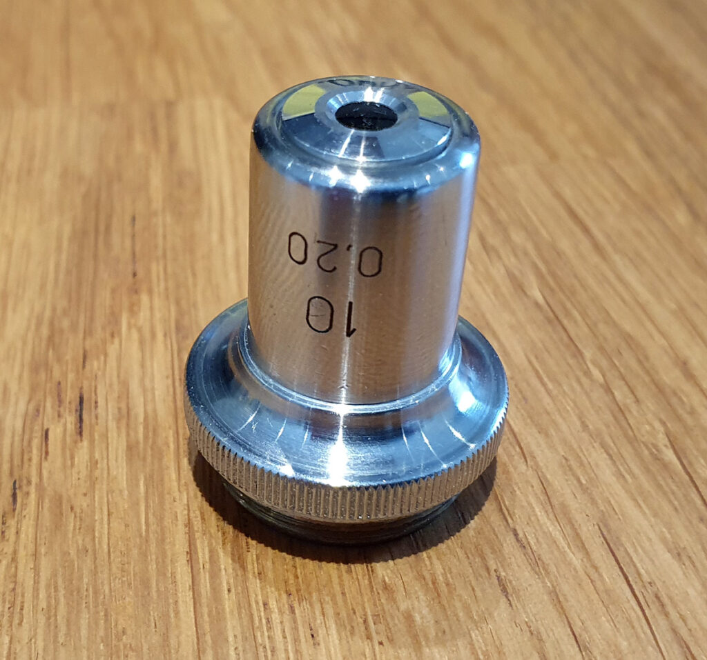
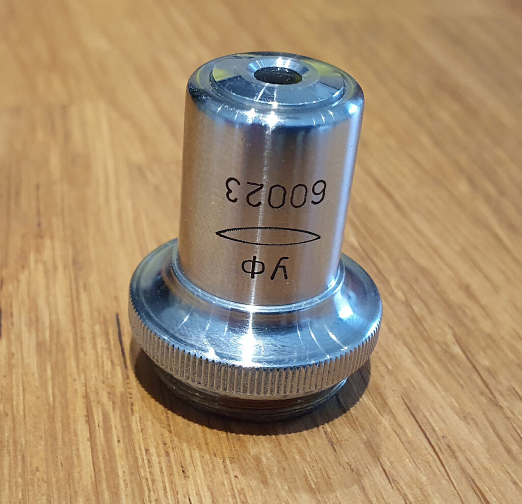
This little objective has an RMS thread, and is for finite tube microscopes. I found one on eBay and including delivery is was less than 100USD. Here’s the objective.

Lomo UV 10x objective

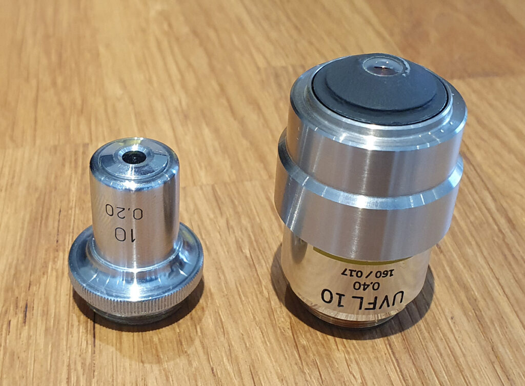
This Lomo objective lens is tiny. Here it is next to my Olympus UVFL 10x.

Lomo UV 10x vs the Olympus UVFL 10x

And here it is mounted on my Olympus BHB microscope.

Lomo UV 10x on the microscope

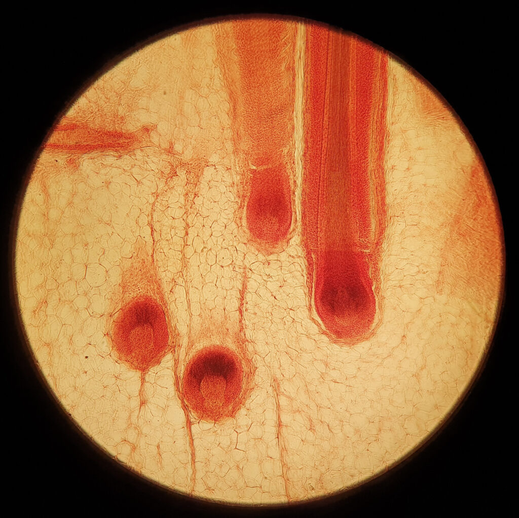
How does it perform? I think OK is about the best way to describe it. The lens shows some softness towards the edge of the image, as shown by the photo below of a skin sample with hair roots which was taken through the eyepiece of my Olympus.

Lomo UV 10x image through the eyepiece

Thing is these Lomo objectives were meant to be corrected by using the right Lomo eyepiece. Thankfully I have a Lomo UV correcting photoeyepiece for this objective, so images taken the right way through the trinocular should be a lot sharper across the image…..

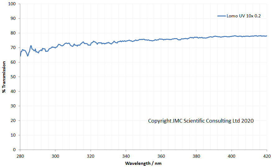
So far what do we have? A little lens with a OK (but not stellar) performance. However this is where the Lomo plays its Joker – its transmission in the UV. I measured the lens transmission between 280nm and 420nm and got this.

Lomo UV 10x transmission between 280nm and 420nm

The transmission curve for the objective shows that it is not a normal glass lens. This is behaving like my Leitz UV and Zeiss Ultrafluar objective lenses, and is made from quartz instead of glass. Although I cannot measure below 280nm with my setup, I reckon this will have good transmission down to below 250nm. As such it is suitable for UVB and even UVC microscopy.

Good things come in small packages as they say, and that is certainly true with this little Lomo. This tiny little objective is a very cost effective way to try out the world of UV microscopy, offering great transmission far down in to the UV region, and I’ll definitely be using this in my UV microscope project. If you want to know more about this or any other aspect of my work you can reach me here.

UV Microscopy – Slides and coverslips

“It’s just the little things, the incidentals….”

While I was at University one of my favourite bands was Alisha’s Attic, and like many I still enjoy putting the old CDs on and listening to music from what feels like a lifetime ago. The line above is from one of their songs, called (not surprisingly) The Incidentals. It came to mind as I was thinking about writing this piece that the world of UV imaging is like this. Simple things which we don’t worry too much about in visible light imaging can have huge impact when working in the UV. So, without further ado, I present the case for the humble microscope slide and coverslip…..

When it comes to microscopy, there’s little which can be thought of as simpler than these items. Pieces of glass used to mount the sample, we take them out of the box, give them a little clean, and then that’s about it. But for UV imaging glass has a bit of a problem. Depending on the wavelengths you use, it isn’t always transparent, which if you’re trying to get light to go through it is a bit of a problem.

UV lighting can be done in number of ways, but one of the common routes for microscopy is to use mercury xenon lamps. These have high UV output, with some very very strong narrow bands superimposed on a broad background of emission. Using filters, you can get narrow UV bands which can be used for both transmission and fluorescence imaging. So what do glass slides look under UV, and how does wavelength impact how they behave?

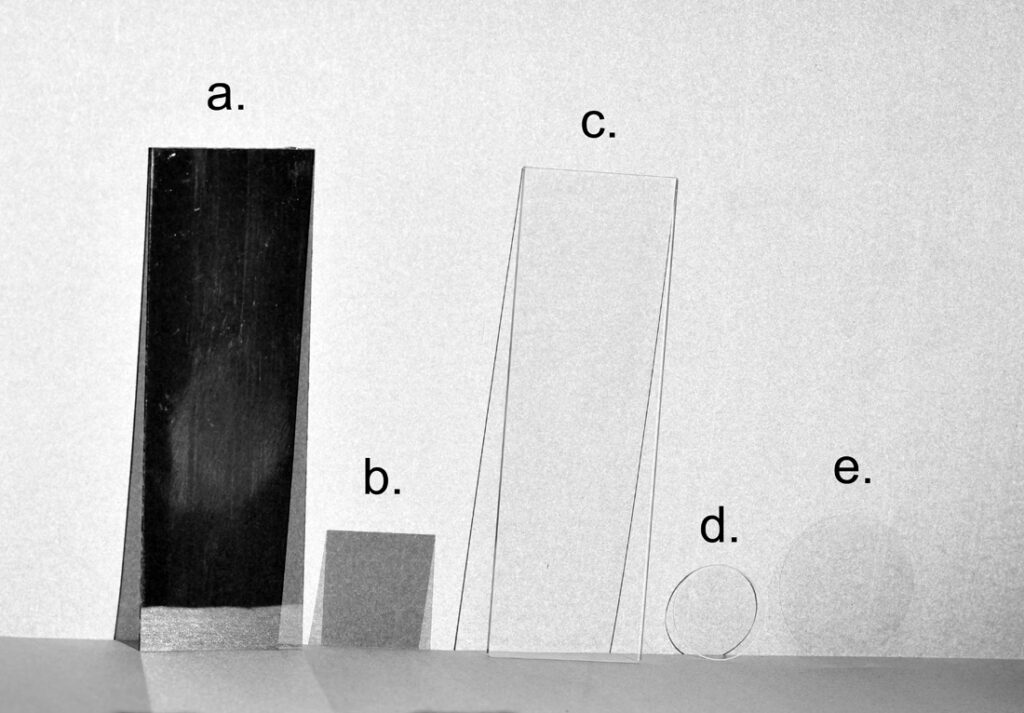
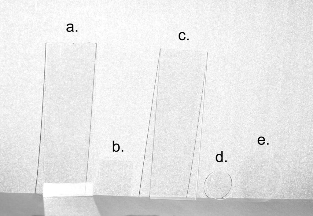
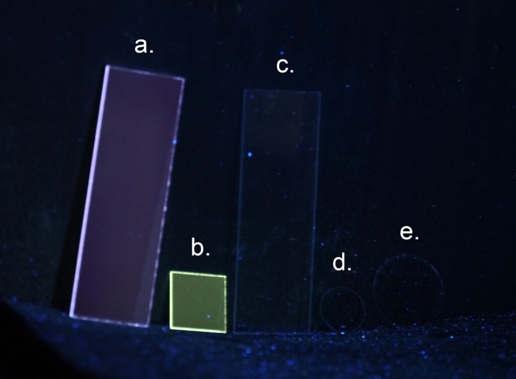
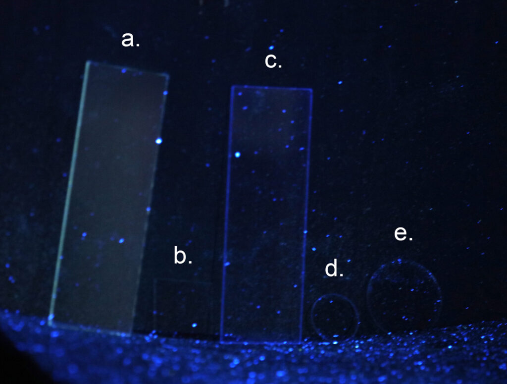
To compare with the glass slides and coverslips, I sourced some quartz and fused silica components from UQG Optics, who I get some of my optical filters from. For my testing I had 5 coverslips and slides; a. Standard 1.1mm thick glass slide, b. standard 0.17mm thick glass coverslip, c. Quartz microscope slide 1mm thick, d. UV fused silica 0.35mm thick coverslip, and e. Quartz 0.17mm thick coverslip.

The first set of images is how they behave with UV transmission. For imaging I used my monochrome converted Nikon d850 camera, a Rayfact 105mm UV lens, and Edmund Optic OD4 band pass filters (313nm or 365nm). Light source was a 200W Hamamatsu LC8 mercury xenon lamp. Slides were imaged against a white paper background.

Here’s how they look at 313nm (UVB region).

Glass (a. and b.) and UV fused silica/quartz (c., d. and e.) at 313nm

And, now the same slides/coverlips imaged at 365nm.

Glass (a. and b.) and UV fused silica/quartz (c., d. and e.) at 365nm

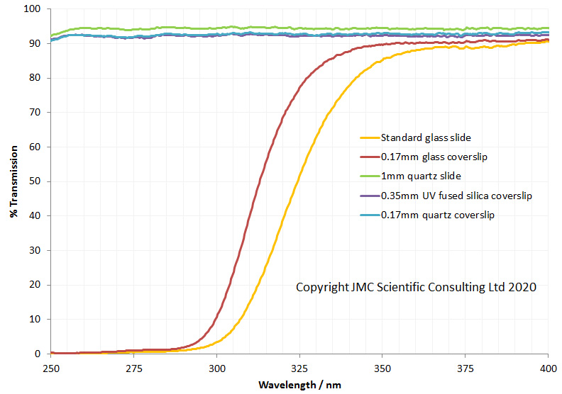
It’s pretty obvious that the glass slide is absorbing most if not all the 313nm light, and even the coverslip which is only 0.17mm thick is absorbing a lot of it. The quartz and UV fused silica components are on the other hand essentially transparent (other than a little bit of surface reflection reducing the effective transmission). At 365nm the story is different. Now the conventional glass slide and coverslip are transparent just like the quartz and UV fused silica ones. I also measured the transmission spectra through each of these using my Ocean Optics spectrometer and deuterium light source.

Transmission through the slides and coverslips

The transmission spectra back up what was seen in the UV images. I can measure down to 250nm with my system, but the quartz and UV fused silica will go on transmitting well below that.

Looking at the results above you may be thinking that the conventional glass slide and coverslip will be fine for UVA imaging at around 365nm. Well, yes and no, and it depends on how you set up your filters, lighting and camera in the system. In addition to how they transmit light you need to consider how they might fluoresce under UV light. To test this required a slightly different setup. The same light source was used, but now the 313nm or 365nm filter was put in front of the light source. The room was completely dark, so the only light came from fluorescence caused by the UV. The samples were placed inside a box painted with Semple Black 2.0 paint (which has high UV absorption and low fluorescence). Imaging was done with a conventional Canon EOS 5DSR camera and 105mm lens, and a 420nm long pass filter (to remove any light not caused by fluorescence).

First, the fluorescence image when illuminated under 313nm light.

Fluorescence at 313nm

And now when illuminated using 365nm light.

Fluorescence at 365nm

At 313nm, the glass slide and coverslip (a. and b.) both fluoresce and emit visible light. Interestingly they are emitting different wavelengths, and even though the coverslip is thin, its fluorescence is very bright. Under 365nm light the glass slide still fluoresces, but now the coverslip looks dark. Very interesting, not only do the normal glass components fluoresce but it is wavelength dependent. Also the specific glass slide and coverslip you have will impact how much it fluoresces, so it pays to shop around. Typically higher priced and higher quality glass will have fewer impurities and lower fluorescence, but that is not a hard and fast rule.

You can also see lots of blue dots in the image, especially with the 365nm irradiation. This is dust from clothes which contains optical brighteners from laundry detergents. It is the bane of UV fluorescence photographers. Rooms which looks clean under visible light, light up like a Christmas tree under UV light due to this dust. It give an overall blue ‘hue’ to the image at 365nm. The quartz and UV fused silica components are effectively non-fluorescent at either wavelength.

The quartz and UV fused silica components offer great transmission, and are non-fluorescent under UV. Why not just use these instead of glass slides whenever working with UV? Well, they have one major drawback, and that is cost. The glass slides and coverslips cost a few pence each. Depending on what they are being used for they can be thought of as disposable – use once and throw away. Anyone who’s ever tried cleaning coverslips will understand why this is the case. The quartz and UV fused silica components are certainly not disposable. The 1mm quartz microscope slides cost around 13GBP each, the 0.35mm thick coverslips also about 13GBP each, and the 0.17mm thick coverslips around 36GBP each!!! Overall, you’re looking at the order of 100x to 1000x the cost of glass equivalents. With that in mind these are not disposable items. The thought of trying to clean a 24mm diameter 0.17mm thick coverslip after use fills me with dread……

UV microscopy presents some unique challenges that visible light imaging does not. Even the choice of things such as the slide or coverslip you use, which may seem inconsequential or incidental under visible light, become vital to consider, especially when looking at short wavelength UV imaging. In fact every component of the optical train needs to be optimised, modified and tested when doing UV imaging and microscopy. If you want to know more about this or any other aspect of my work, you can reach me here.
UV transmission of Zeiss Luminar lenses

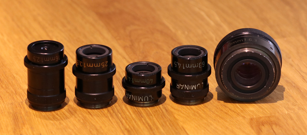
In the world photomacrography the Zeiss Luminar lenses have an almost mythical status. Originally intended for use in their Ultraphot range of microscopes, they have the ability to form a very large image circle – enough to cover a 4″ x 5″ plate – when used at their specified magnification range, and to do that without additional eyepiece optics. Available in the range of focal lengths (16mm, 25mm, 40mm, 63mm and 100mm) and with a number of different versions depending on when they were made, they offer extremely high sharpness and resolution, even compared to modern lenses.

A few months ago I bought one of these lenses – the 25mm one – and was really impressed by it (see here). In addition to being a really sharp lens, it also had great UV transmission. This got me wondering whether the other Luminars could also be used for UV imaging work. The 100m one I got was a great macro lens, but did not work that well for UV, as it had poor transmission (you can read about that here). The other Luminars do come up for sale on eBay reasonably, and they command high prices (often too high, as some of them stay ‘for sale’ for a long time). However a few days ago a friend of mine contacted me to say he had three of them in 16mm, 40mm and 63mm for sale. The price was right and they arrived here yesterday. Along with the other 2 I already had, these completed the set. And here they are….

The 5 Zeiss Luminar lenses

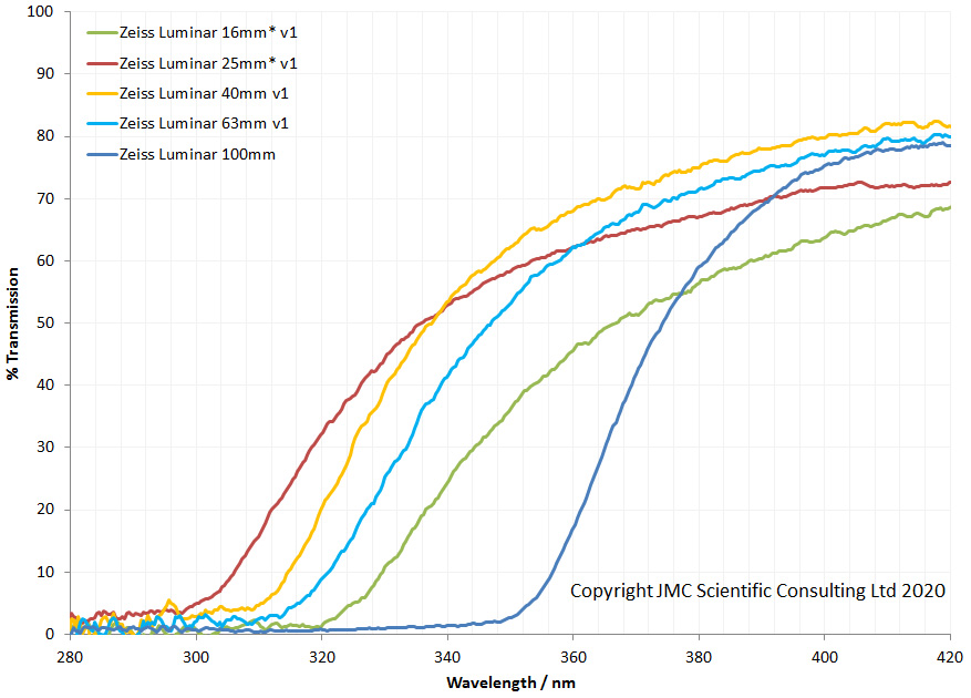
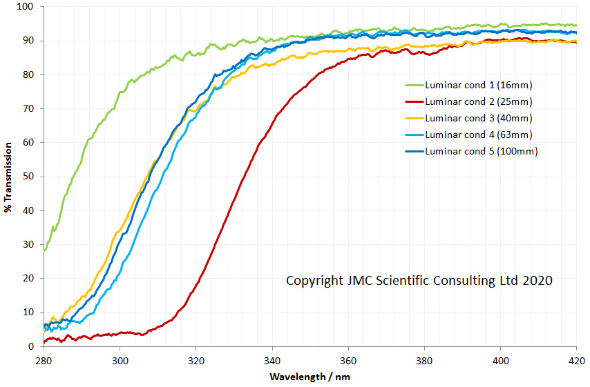
While there is some anecdotal information on their UV capabilities, I had not seen any actual data comparing all five of them for transmission. So, that was my first job, using my own lens transmission rig.

Luminar lens transmission between 280nm and 420nm

This revealed some interesting findings. The 25mm reached the farthest into the UV, and the 100mm showed the least UV transmission. The 16mm one is the 2nd worst. This one has a relatively complex lens design so its behaviour makes sense (5 elements, 4 groups). I had expected the 40mm and 63mm ones to be better than the 25mm one, as they have fewer elements (3 elements, 3 groups, vs 4 elements, 3 groups) but this was not the case. These are minor points though – the 16mm, 25mm, 40mm and 63mm ones all give good UV transmission for the majority of photographic purposes where it is mainly UVA that is being imaged.

Note, the 16mm and 25mm ones are marked with an * in the graph as the apertures for those are very small, and I suspect might be clipping the light beam slightly during the measurement. Therefore the absolute transmission for those are likely slightly higher than in the graph, bringing them in line with the other three. This does not impact how far into the UV they transmit though.

Overall, the 16mm to 63mm ones all look to offer a good to degree of UV transmission especially for UVA imaging, so I’ll definitely be using these in future for macro and UV work. They also have RMS threads and fit my Olympus microscope, so I will use them for some microscopy too.

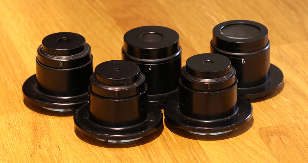
The story doesn’t quite stop there though. When the Luminars were in use on the Ultraphot microscopes, they also had a set of spectacle lens condensers that went along with them – one for each Luminar lens. The same day I was offered the 16mm, 40mm, and 63mm lenses, I came across an advert on eBay for a set of the 5 condensers which I had never seen before. Here they are.

Zeiss Luminar condenser lenses

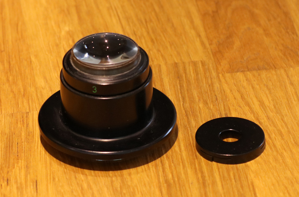
Each one of these has a removable clip on diaphragm.

Diaphragm removed

When it came to UV transmission for them I expected them to all be about the same, perhaps with slight variations as a function of glass thickness. Turns out they are not though.

Luminar condenser lens transmission between 280nm and 420nm

The condenser for the 16mm Luminar reaches much further into the UV than the others, and the one for the 25mm Luminar has the highest cutoff. The others are about the same. As I’m currently building a UV microscope, the Condenser for the 16mm Luminar has about the best reach into the UV that I have seen so far and I’ll try that one out. However these are a different diameter to my Olympus microscope condenser mount, so I’ll need a little adapter to be made up to use them.

I went into this assuming the 40mm and 63mm Luminar lenses would have better UV transmission than the 25mm given their simpler optical designs. I also assumed that that the condenser lenses would all be about the same. As we all know though ‘assume’ makes an ass out u and me. Just goes to show that it’s hard to predict lens behaviour in the UV, and that testing is the only real answer. If you’d like to know more about this or any other aspect of my work, you can reach me here.
Project Beater – Melanin imaging in human skin

Melanin acts a primary skin defense against UV, helping to absorb it before it can reach too far into the skin. I was intrigued by what skin with a high melanin content would like like under the microscope and recently managed to find a prepared slide of highly pigmented skin (I’m guessing Fitzpatrick V or VI) and wanted to share some images, as they nicely show the melanin.

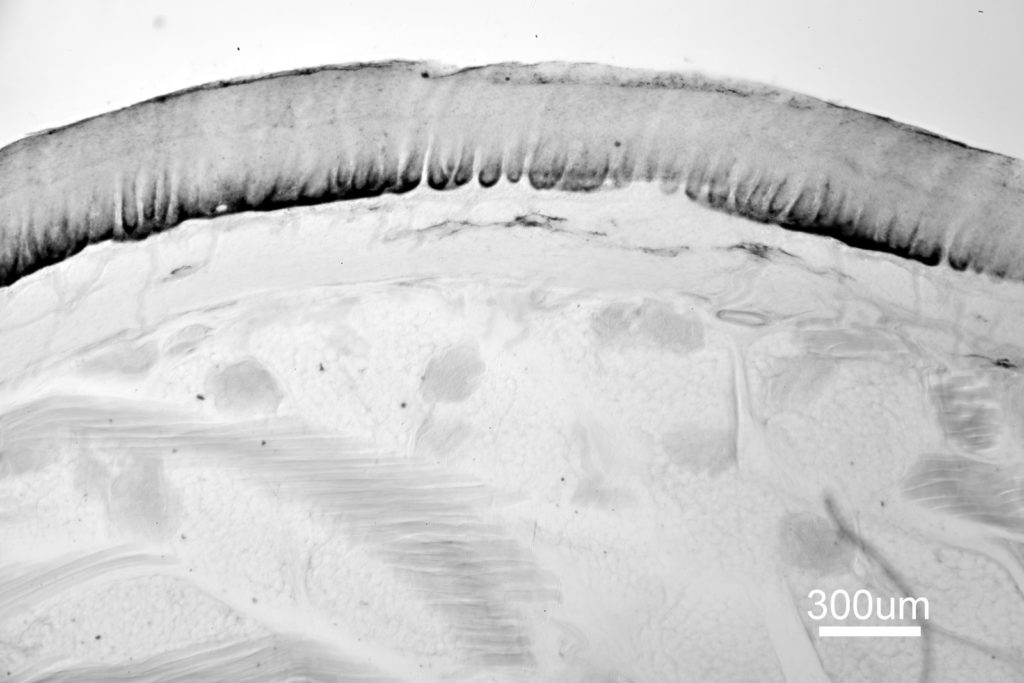
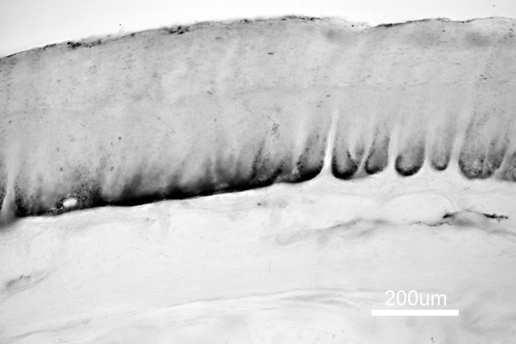
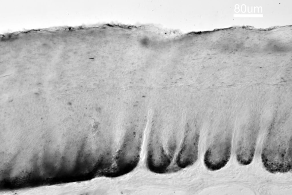
These were taken on my Olympus BHB (affectionately named Project Beater, given the state it was in when I bought it). The light source was just the standard tungsten filament bulb, and the images are all bright field. Objectives between 4x and 63x were used, and approximate scale bars included in the images (which are just single shots, no focus stacking). Camera was a Nikon d850 monochrome conversion, with no filtration. Here are the images;

Pigmented skin cross section with 4x objective
Pigmented skin cross section with 10x objective
Pigmented skin cross section with 16x objective
Pigmented skin cross section with 63x objective

As can be seen in the 4x image, the skin sample includes the stratum corneum (top on the image), and the viable epidermis, the dermis and the subcutaneous tissue. At the bottom of the viable epidermis, where it interfaces with the dermis, there is a really dark layer. This is where the melanocytes are present, and they produce the melanosomes (the pigmented melanin granules). These melasomes are then transferred into the keratinocytes, which through the process of division and differentiation are pushed upwards and eventually form the corneocytes of the Stratum Corneum, taking the melanin with them.
In the image with the 63x objective we are now looking at the top layer of the skin, the flattened corneocytes of the Stratum Corneum. At this magnification you can see individual and clusters of melanosomes, which appear as black dots in the image. Amazingly these are sub micro in size – literature gives sizes of a few hundred nanometers across for them.

The images here were taken with normal visible light lighting. It’ll be interesting to come back to this slide at some point with UV imaging as melanin absorbs more light at shorter wavelengths. I’d also like to try some higher magnification images with focus stacking to see if there is more detail to be had with the melanin granules.

Microscopy opens a window into worlds we cannot see with the naked eye, and the more I research it the more I am fascinated by the images it can produce. Thanks for reading, and if you want to know more about this or other aspects of my work, I can be reached here.