With some experiments, the end result is fairly easy to predict. Others, not a chance. With this piece of work I had no real idea what to expect, or even whether I’d be able to see anything at all. Essentially, it was this – can I image at 254nm using the equipment that I already have?
To start with some background. I have an interest in UV photography because of my work on sunscreens, and as part of my research in the area, I’m always looking to push the limits of what can be photographed with the kit that I have. My monochrome converted Nikon d850 camera has a really nice sensor for UV, visible and IR imaging, and I was able to measure the spectral response of it down to 280nm which is the limit of my measurement capability. At 280nm there was still a little bit of sensitivity there, but it had dropped to almost nothing and I’d assumed (always dangerous) that below 280nm it would be essentially zero. When it comes to UV imaging, very often specific wavelengths are discussed, as they correspond to lines in the mercury emission spectrum. 365nm and 313nm are quite strong emission lines, and they lay within the UVA and UVB regions respectively. However drop below 280nm and you get in to the murky world of UVC. While there is UVC in light coming from the Sun, it does not reach ground level as the atmosphere blocks it. However there are artificial sources of UVC. Welders are often exposed to it due to ionisation of the air and metal, where it can result in bad burns to skin and damage to the eyes, and in our new Covid related world UVC sterilisation of surfaces is becoming more and more widespread. This got me wondering whether I could break through into the UVC region and capture photos at 254nm which is another one of the strong mercury emission lines.
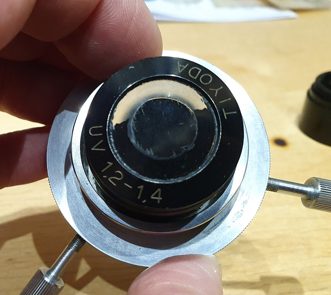
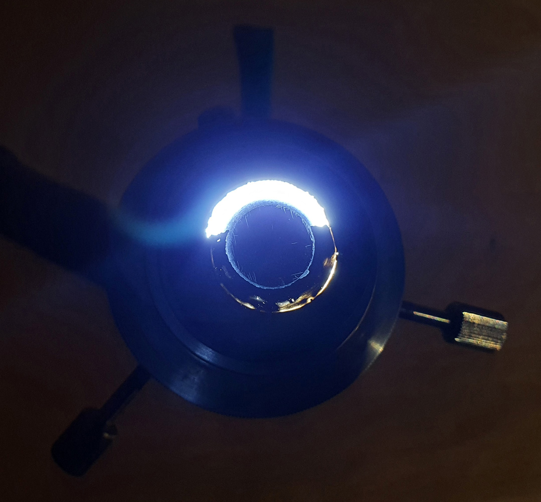
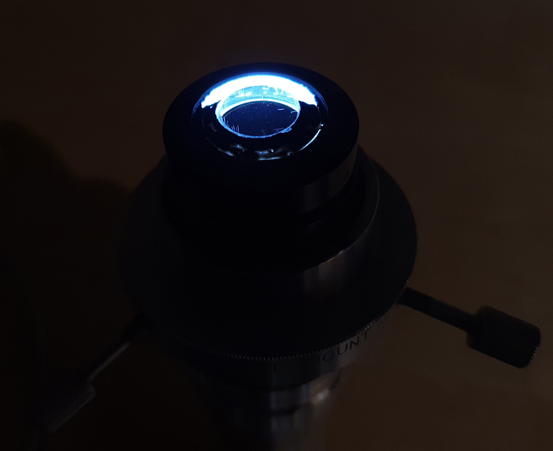
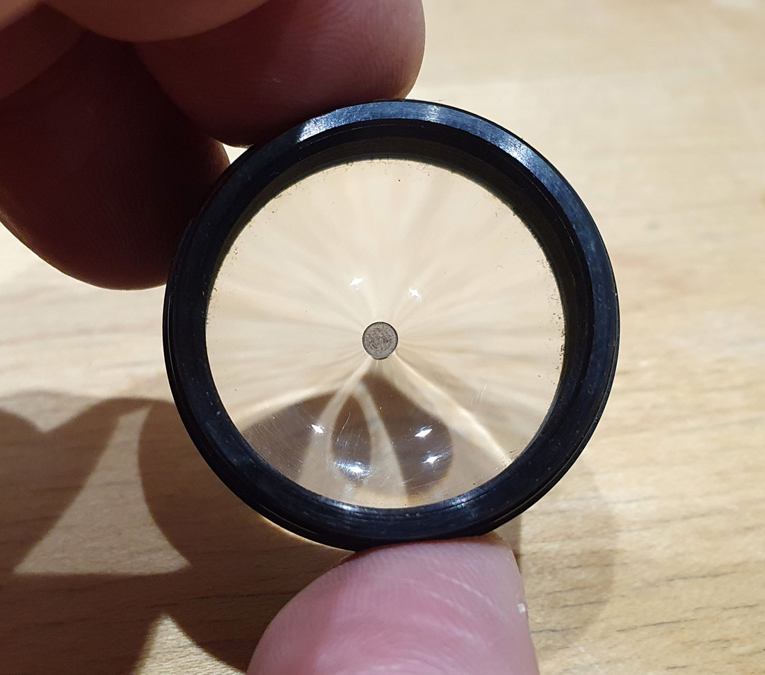
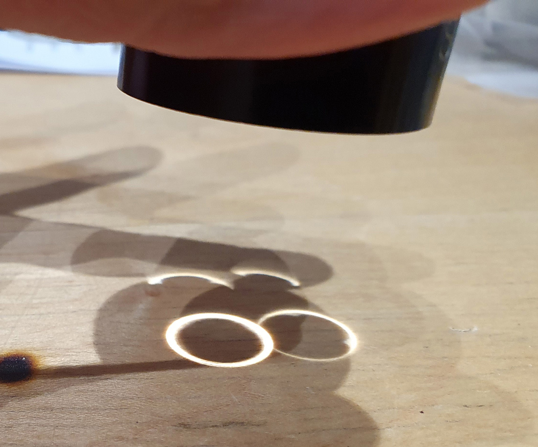
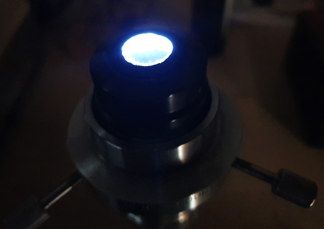
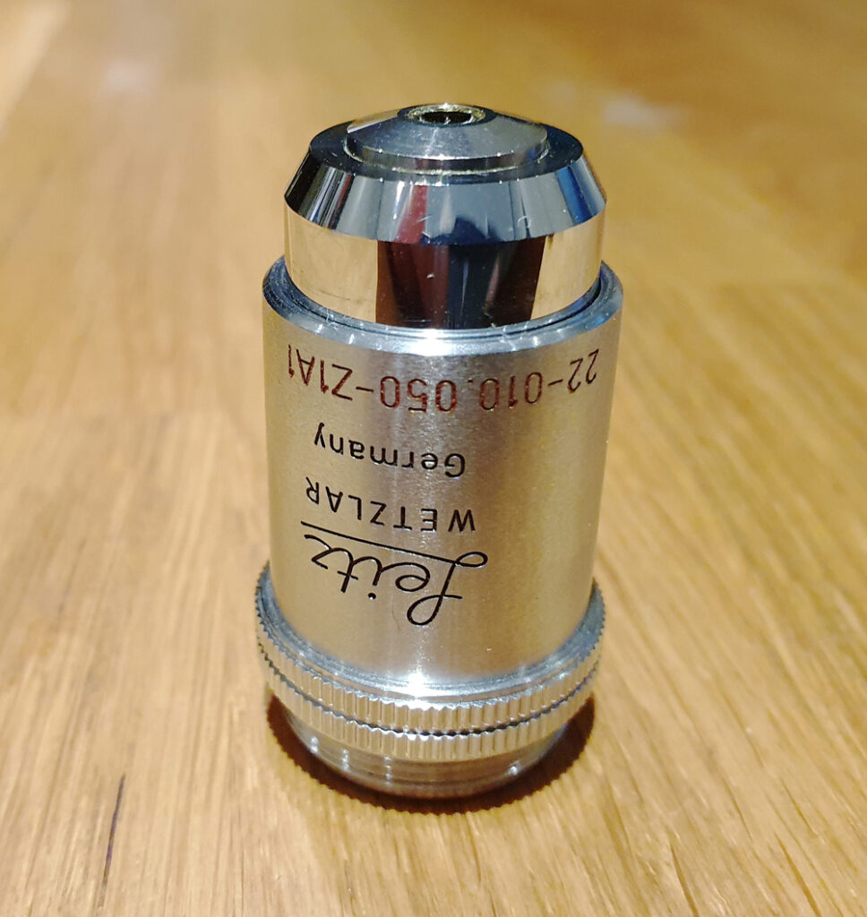
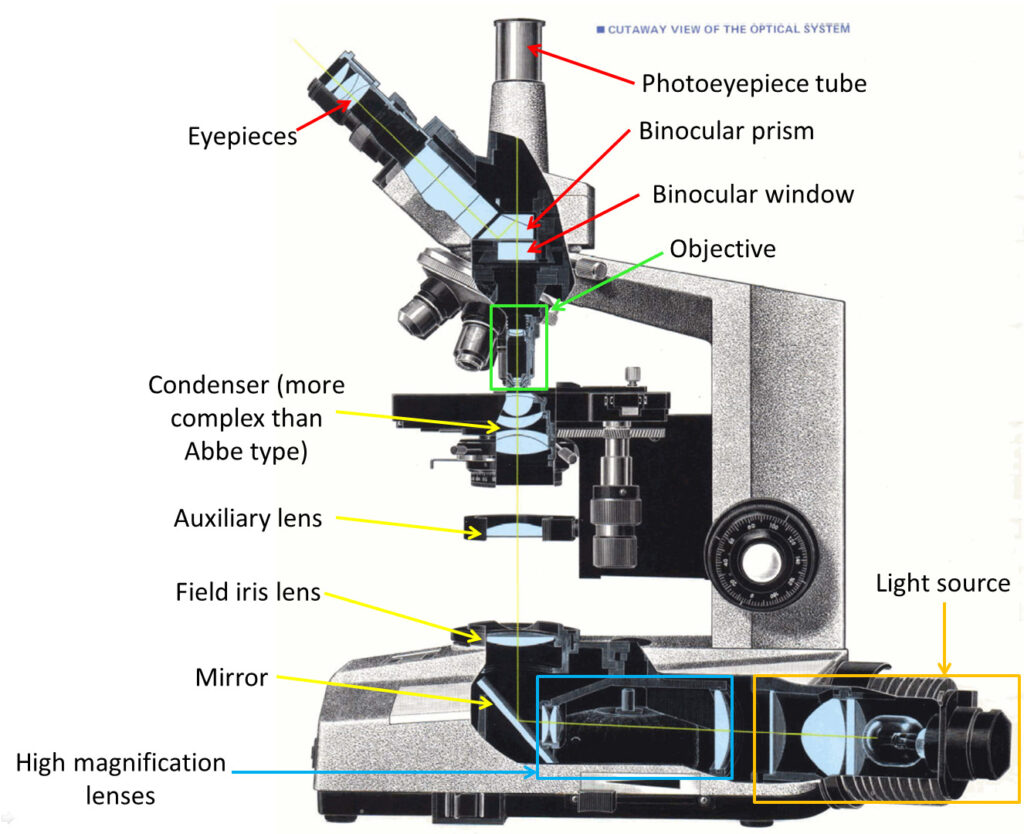
This would be no simple task. Even if the camera was sensitive enough to capture an image there, the sensitivity it has would be extremely low, meaning that the presence of any other wavelengths would completely swamp the signal from 254nm. Therefore really good filtration would be needed. For the filter I used a 254nm bandpass filter I got from a Sirchie forensics camera a while back. While it has relatively low transmission at 254nm, it has good out of band blocking, and it meant I didn’t need to spend a fortune on a new filter. Any glass in the lens would absorb the UVC, so I chose the 105mm Rayfact UV lens for this experiment – it has quartz and calcium fluoride lens elements instead of glass and is good for using down to around 220nm. Camera was my monochrome converted Nikon d850 from MaxMax. When I had this made I requested a fused silica sensor window, in case I ever wanted to go below 280nm. Light source was an interesting one. In the end I got a pair of 8W 254nm UVC fluorescent tubes from ‘a well known internet auction site’. These are normally used for sterilisation of water, but they fit my UVP UV lamp so I thought I’d try them out. Subject wise, a small vase with a couple of feathers and a Spectralon 20% diffuse reflectance standard was chosen.
For imaging, everything was done in a dark room, and the subjects were placed in a box painted with Semple Black 3.0 paint which has low reflectance and low fluorescence, to cut down on stray light. I wore UV protective glasses (in fact that point deserves capitals – I WORE UV PROTECTIVE GLASSES – please do not play around with UVC lights without wearing these). In addition to imaging the subject using the 254nm filter, I also took another image with a Schott WG305 long pass filter in front of the 254nm filter, to check for stray light getting through.
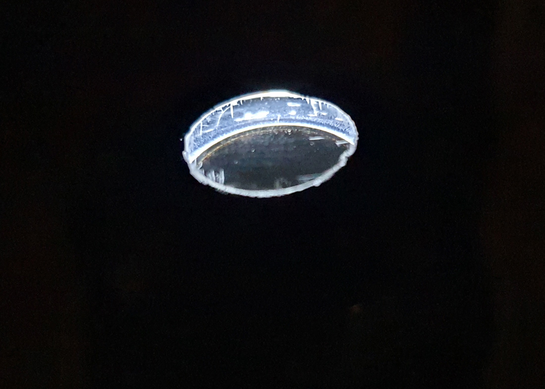
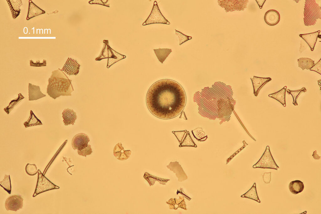
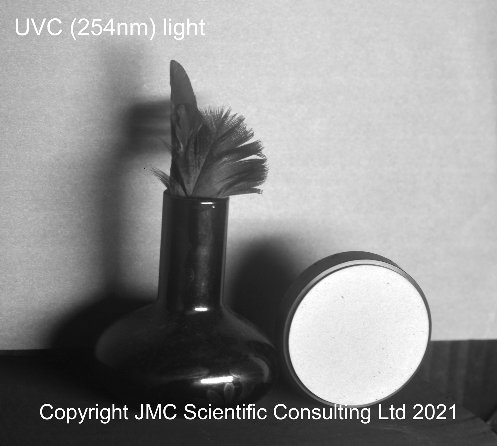
Right, that is far too much waffle. Was it possible to capture a UVC image with this setup? Well, yes it was, and this is what it looks like.
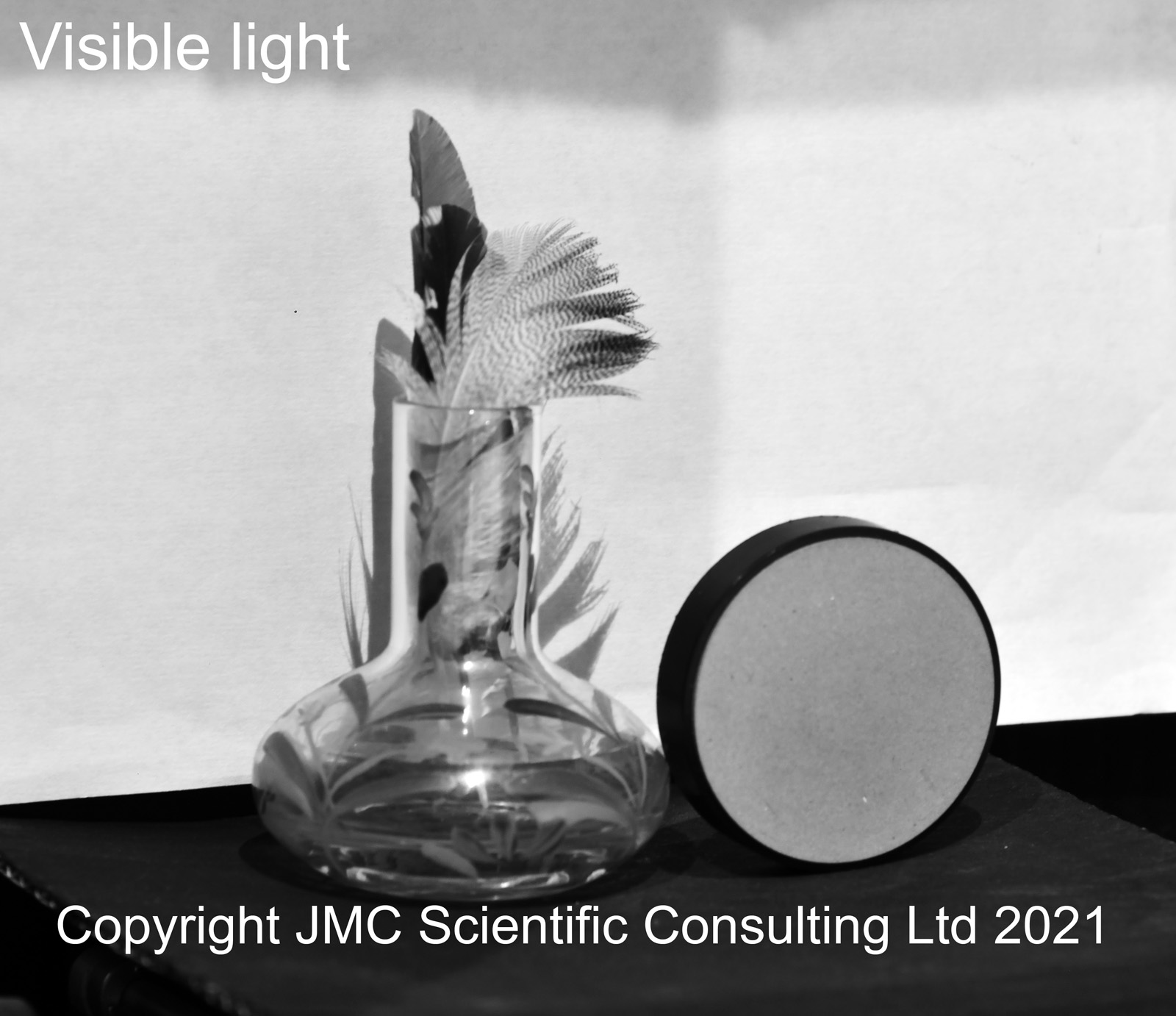
Just for comparison, here it is when imaged in visible light.
The first thing to note was the vase – the glass looks black in UVC. This is because the glass strongly absorbs the UVC. How did I know this was a UVC image? It’s very easy to fall into the trap of assuming that this is a UVC image, but by using a Schott WG305 long pass filter as well I could block the UVC while letting longer wavelengths through, and this is what I got with that.
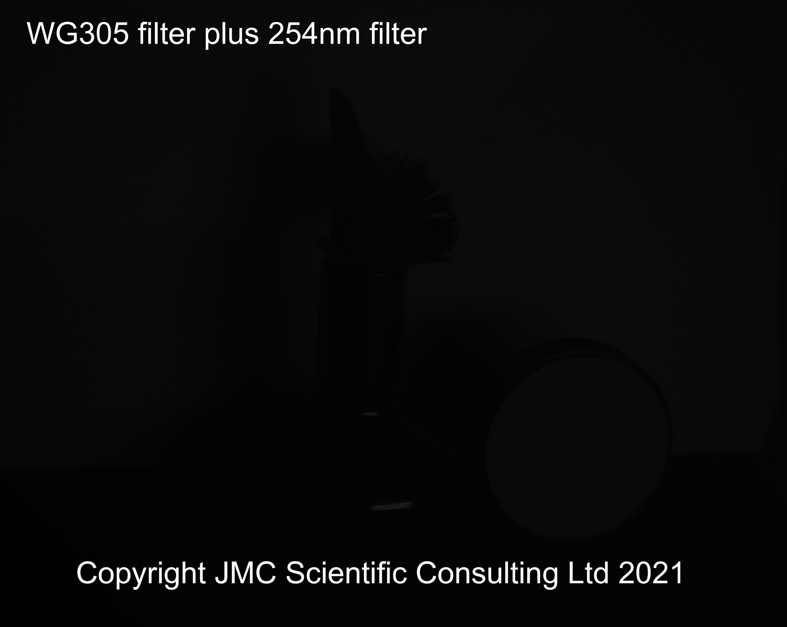
While it is hard to see online, there is a really faint image here with the Schott WG305 filter in place, so it is fair to say that my 254nm image, while predominantly UVC is not all UVC and there is a tiny amount of contamination of the image by longer wavelengths. However it is fair to say that the image with the 254nm filter alone is mainly a UVC image.
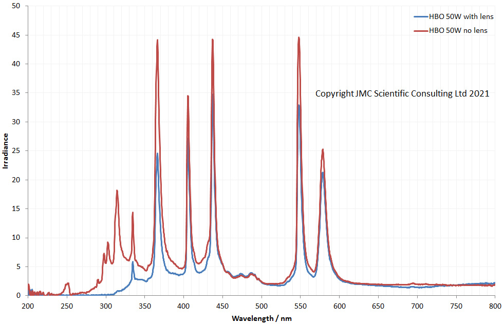
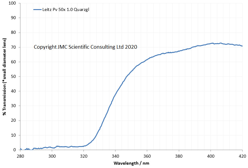
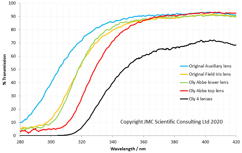
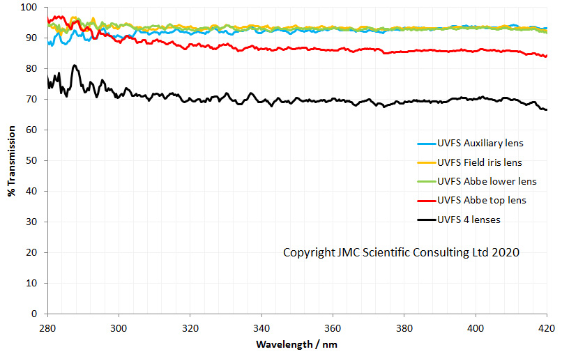
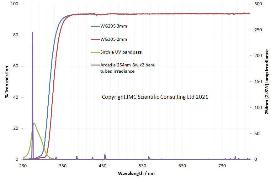
At this point it is worthwhile looking at the properties of the filters and the light source to help explain what is going on. Here they are between 230nm and 800nm.
And now between 230nm and 430nm.
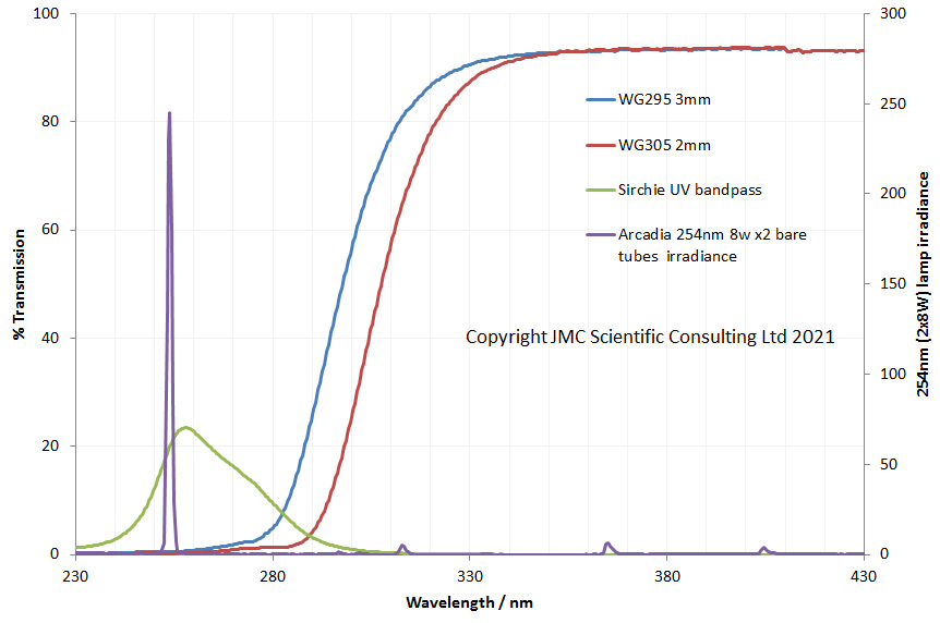
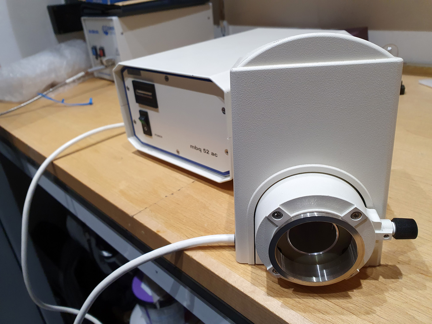
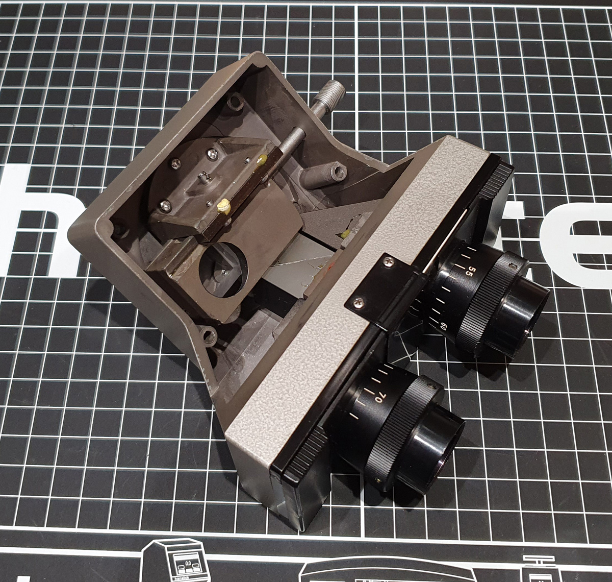
What are these graphs telling us? The light source (the purple line) has a strong emission at 254nm, with a few very small peaks at longer wavelengths. There may well be more lines 800nm but I cannot see up there. The peak transmission of the 254nm band pass filter (the green line) coincides with the 254nm lamp which is good. The red line (WG305 filter) is the filter I used to check for leaks and as you can see there is a little bit of an overlap with the tail of 254nm filter at around 300nm, and this could be source of the faint image in the WG305 photo above. I may try a slightly longer wavelength long pass filter to check that. The blue line is a ‘red herring’, as I haven’t included images with that filter here, but it is another long pass filter and was part of my other tests on the setup. Here’s a snap of the setup I used to capture the images.
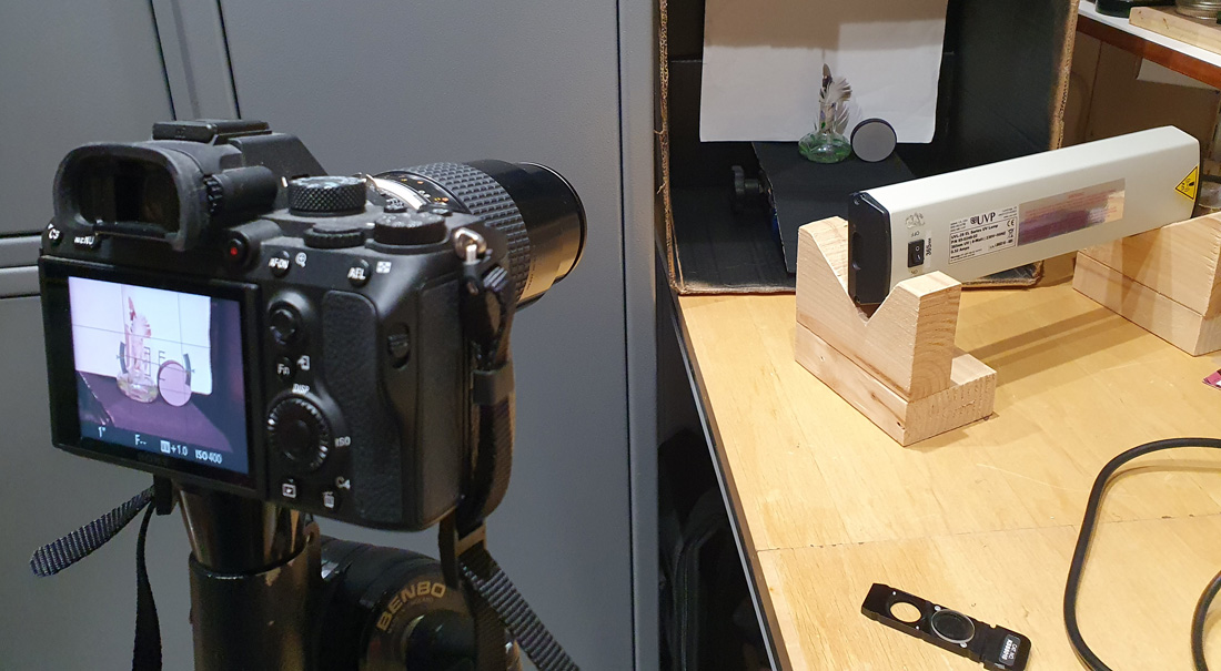
The observant amongst you will notice that the camera in the image above is not a Nikon d850. It is actually my Sony A7III which has been converted to multispectral imaging. This camera, unlike the d850, still has it’s Bayer filter though, so can capture colour UV images. More to come on that, as I’ve been able to get colour images down in the UVC region with it…..
When this experiment started, I honestly did not know what to expect. I’d assumed that the camera wouldn’t be sensitive enough to see anything this far down, but I was wrong and the camera is indeed sensitive enough to see 254nm light. Always nice to be surprised and this opens up its possible uses to new areas such as coronal imaging. Filtering will need some more work, as it’d be good to get a more narrow band pass 254nm filter, but for now this one will do the job.
If you’ve made it this far, well done and thanks for reading. If you’d like to know more about this or other aspects of my work, you can reach me here.