
Some of the experiments I do fall into the ‘Please feel free to try this at home’ category. Others however are of the ‘Do not attempt to do this yourself without full understanding the risks involved. No really, I mean it, stop what you are doing now and step away from the work bench’. Today’s post is firmly from the second category. Please do not attempt to do anything like this unless you understand the risks of working with high intensity UV light. With that out of the way, let’s begin….
For my UV microscope build, almost everything has needed modification in one way or another, in order to be usable down in the short wavelength range of UV below 300nm. My main UV light source – a 200W Hamamatsu LC8 mercury xenon lamp – gives out plenty of UV down to just below 300nm, but is really awkward to use with the microscope, due to the position of the output from the lamp. I have a couple of mercury xenon lamps for microscopes – a 100W Olympus one, and a 50W Zeiss HBO – but when I initially checked the output from both of these there was a bit of a problem. While they both had a good output at 365nm, down below 320nm there was essentially nothing. If I’m wanting to look down at 300nm and below, this is a bit of an issue as I need light down there. Initially it struck me as a bit odd, and had me wondering what was going on. Both microscope lights were using mercury xenon lamps like the Hamamatsu LC8, so why was output so restricted? Perhaps the bulbs were made of different materials which didn’t have as good a UV transmission? This could be possible, but it would be very odd. So was it something else?
For now I have settled on trying to use the Zeiss 50W HBO setup rather than the Olympus one. This is mainly driven by space constraints – the Olympus light source is huge, and I just don’t have space to have it out on the bench all the time. The Zeiss HBO is dinky, so is much less of an issue to leave out. Here it is on the bench.
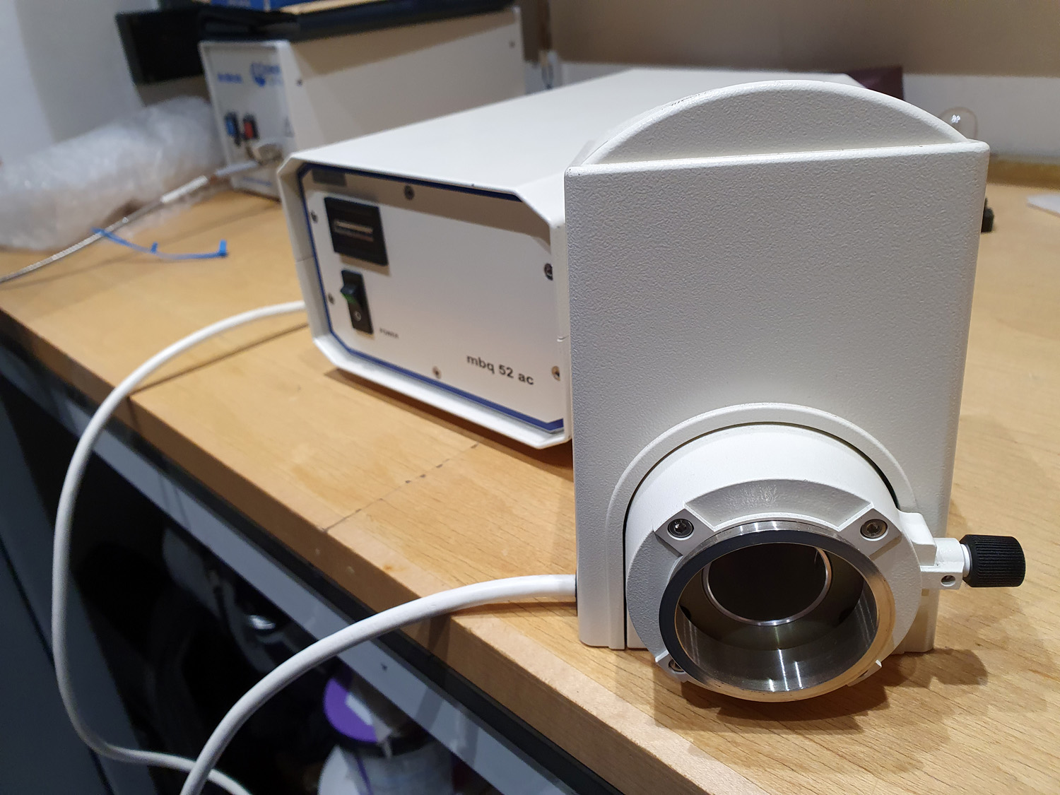
If you look down the output port of the light (with it switched off obviously), there is a metal tube which can be moved in and out by turning a knob on the side of the light housing.
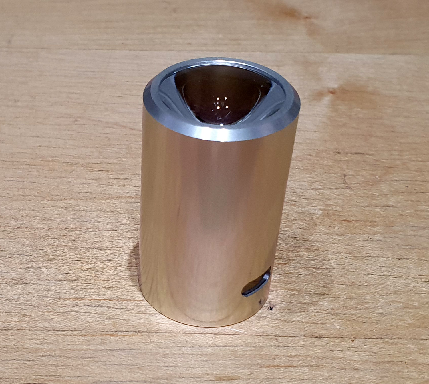
At the far of the tube near the bulb itself is a lens, and the movement of this tube and lens actually focuses the light. But the lens is a problem. It is highly unlikely that this lens is a UV fused silica or quartz one, so it’s going to be glass, and glass absorbs short wavelength UV. This lens will be blocking the light that I want to see. To determine if this was indeed what was happening, the first thing to do was remove the tube and lens. This was actually pretty simple, by loosening the small screw near the focus knob. Once removed, the tube looked like this.
The lens is held in with a simple spring clip, but this was down at the bottom of the tube and was really, really tricky to get out. Once out, the lens itself could be removed, and this is what it looked like.
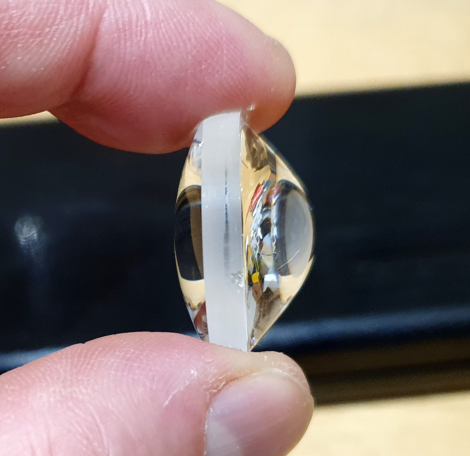
It’s a odd looking, asymmetric design, with the highly curved side facing the bulb. Focal length was about 20mm, which make sense given where it sits in relation to the bulb. Once removed I could measure the irradiance spectra of the light, with and without the lens to see what effect it had on the output. This aim here was not to determine absolute irradiance, but to understand the relative output with and without the lens to understand what wavelengths it was absorbing. For this I used my Ocean Optics FX spectrometer, and got the following.
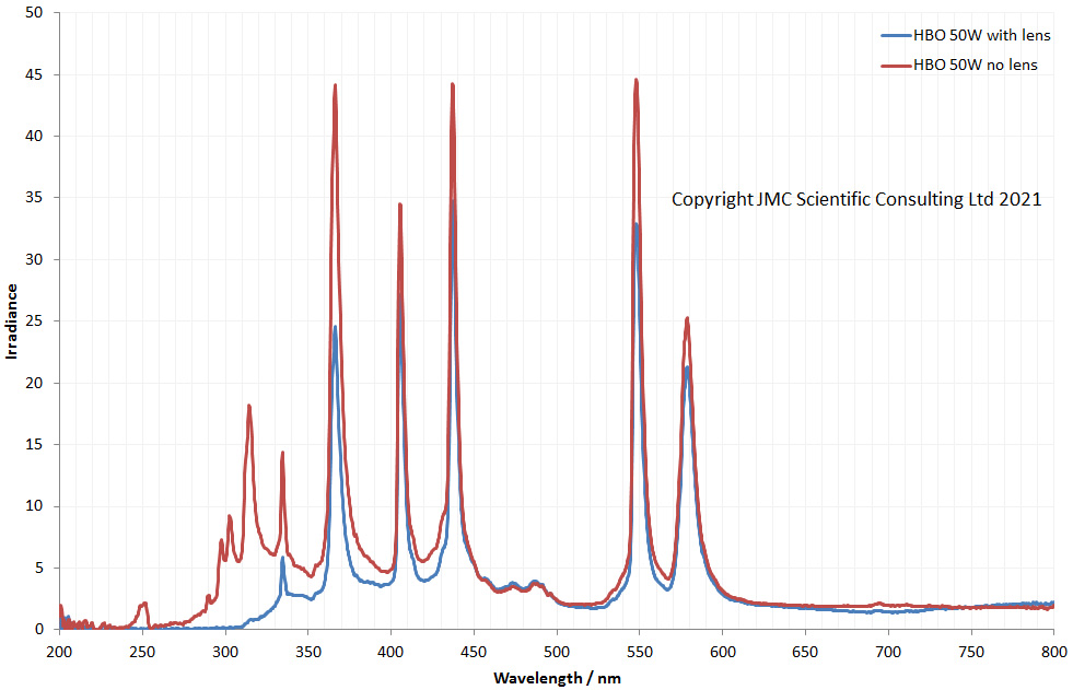
The really obvious difference between the two plots is in the UV region – with no lens in place there are a lot more lines there than when the lens is in the way, especially below 350nm. To try and show this better I normalised the lines to the 578nm peak (which should be pretty similar whether or not the lens is there), and replotted the graphs with an emphasis on the UV and near-visible region.

Plotting the data like this really emphasizes the effect of the lens. With the lens in place the 365nm line is starting to be attenuated. By the time you get to 330nm, most of the light is absorbed, and then below 310nm there is nothing, all the UV has been blocked. With the lens removed, there are still well defined UV peaks at 313nm, and even below 300nm, down to where the spectrometer reaches the edge of its calibration at 250nm. This is not a huge surprise – that lens is thick, and there’s no wonder it is absorbing loads of the UV. Success then, removing the lens brings back the peaks I’d expected from a mercury xenon lamp. Yay.
Simply removing the lens means that this light source can be used for UVB imaging at around 300nm and even below. What is the downside here though? Removing the lens means losing some light intensity, as the light is no longer focused. But in theory I could replace the lens with a planoconvex lens of around 20mm focal length, so give me some rudimentary focusing capability. I could even use a custom UV fused silica condenser lens, but this will be an expensive option. While probably not as good as the complex shaped lens originally used, a simple planoconvex lens should offer improvement over no len, and is something I may consider in the future if light intensity isn’t sufficient.
What have I learned here? Well I certainly know a lot more about the inside of mercury xenon lamps now. Not everything works the first time (and no, this is not the first time I have realised that). However think logically and approach a problem systematically and a solution can usually be found. While I have gone quickly through the description of what I did here, I must emphasize that working with these types of UV lights is not without risk. Exposure to the skin can quickly result in burns, and to the eyes can result in blindness. I made sure I was well protected when doing this work.
Another part of my UV microscope build can now be ticked off, and I am one step closer to being able to image in the 300nm region and below for my sunscreen work. 2021 is starting to look better already……. Thanks for reading, and if you’d like to know more about this or any other aspect of my work, you can reach me here.