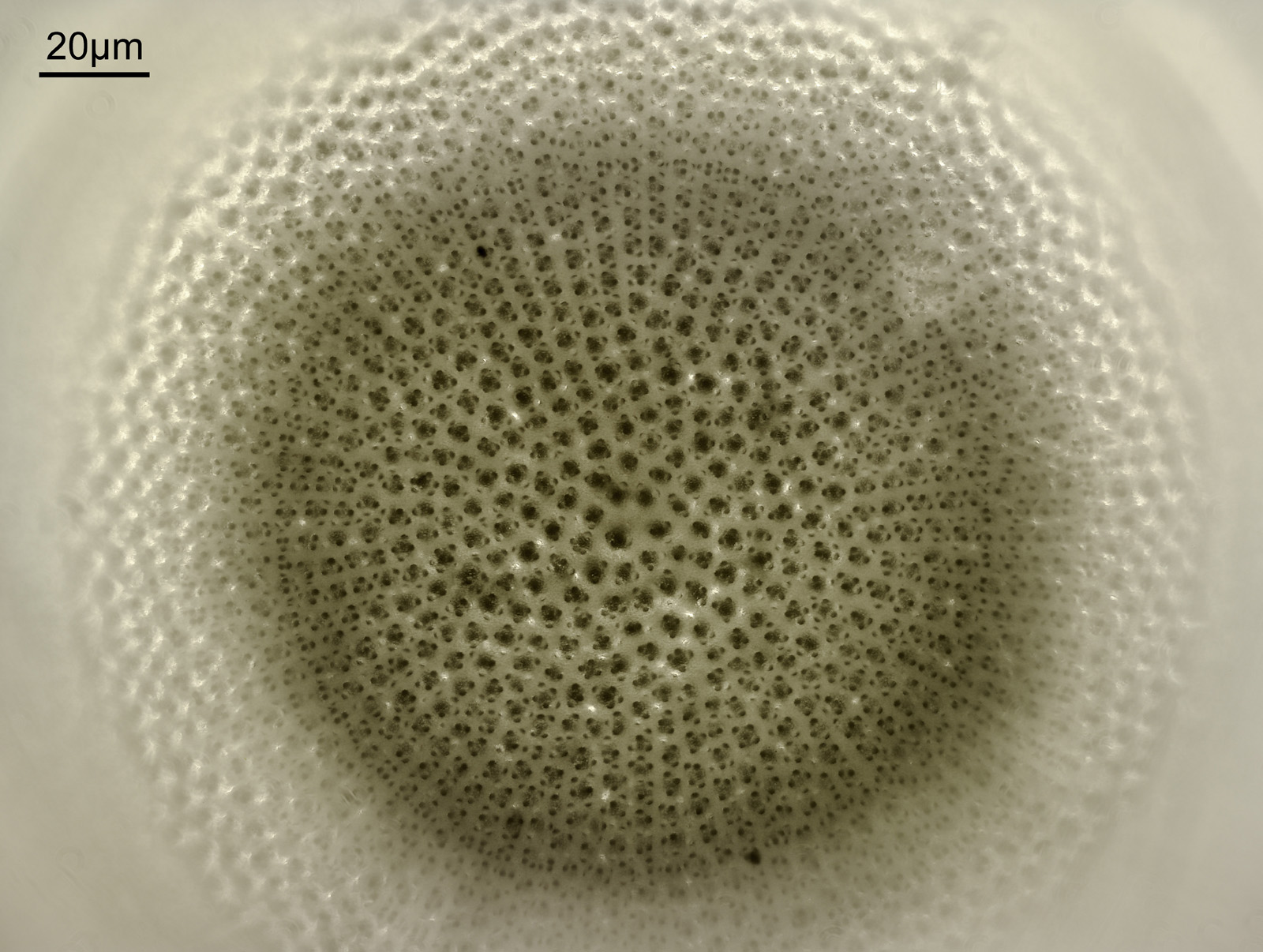
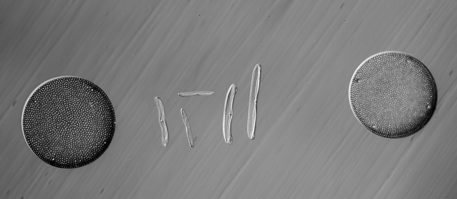
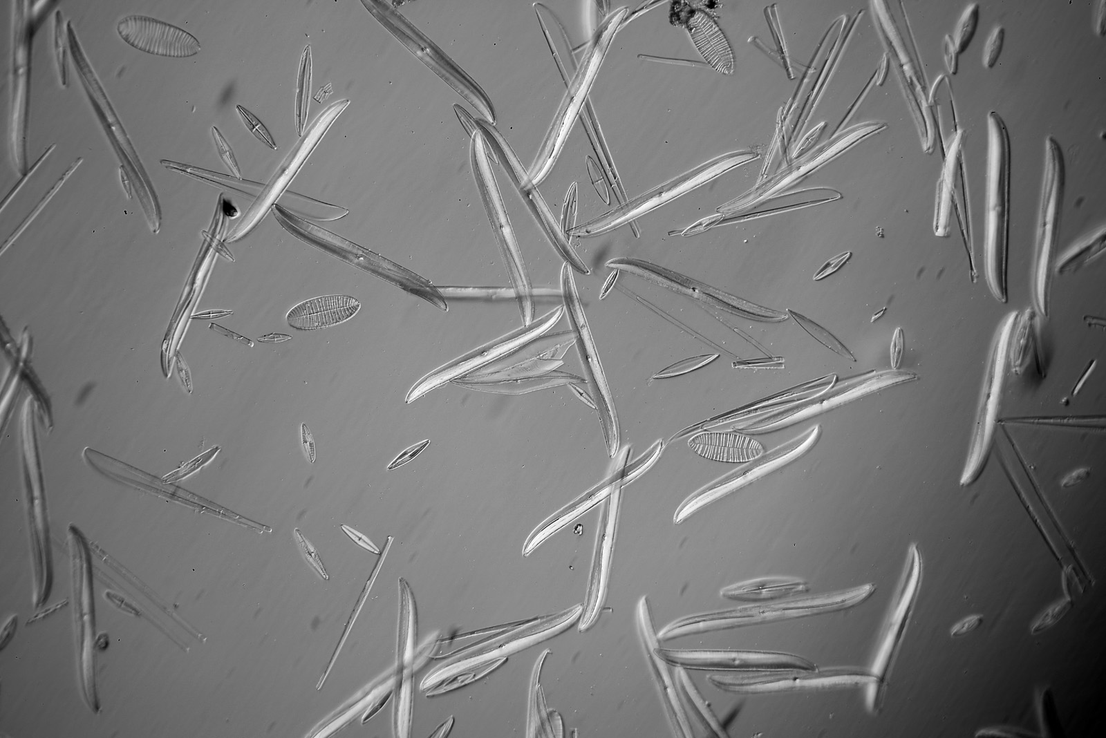
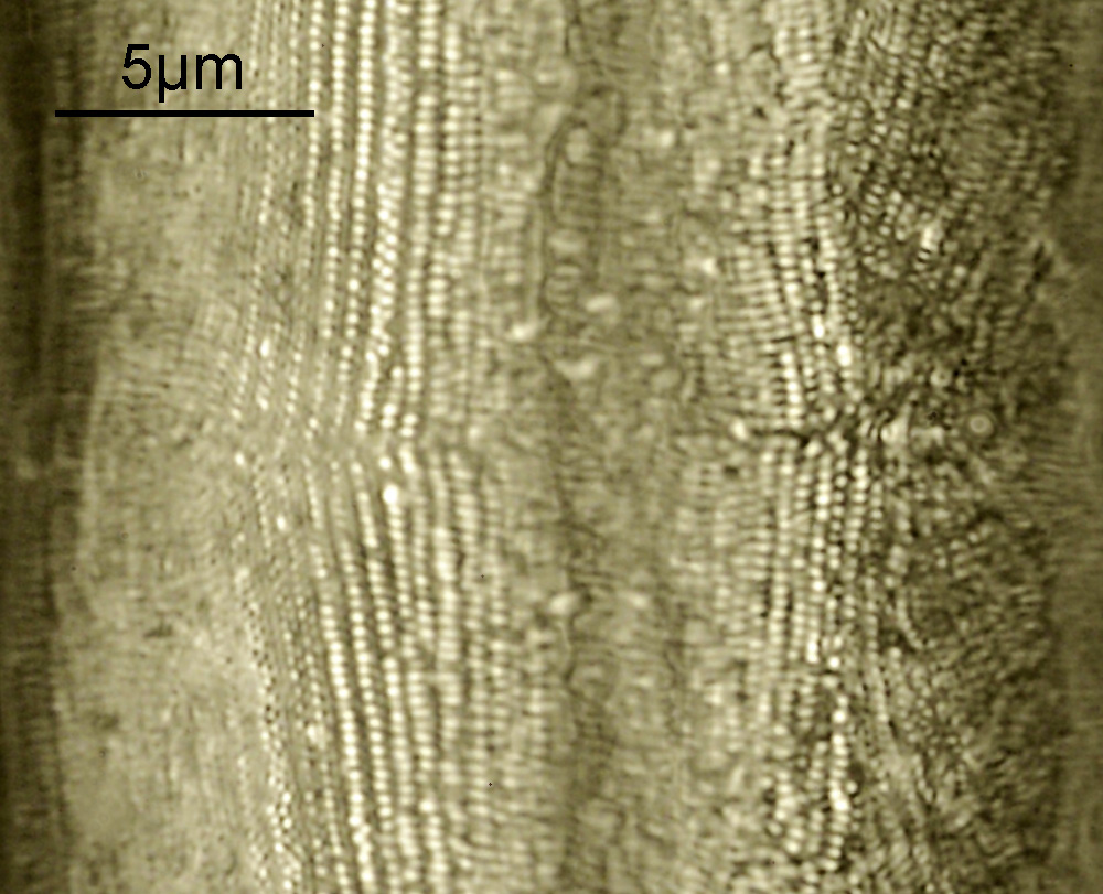
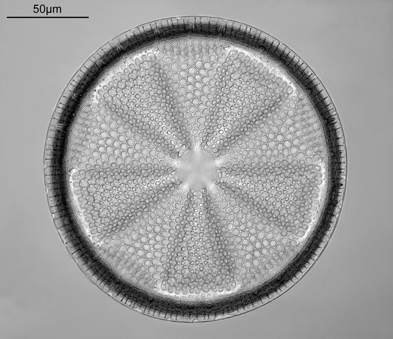
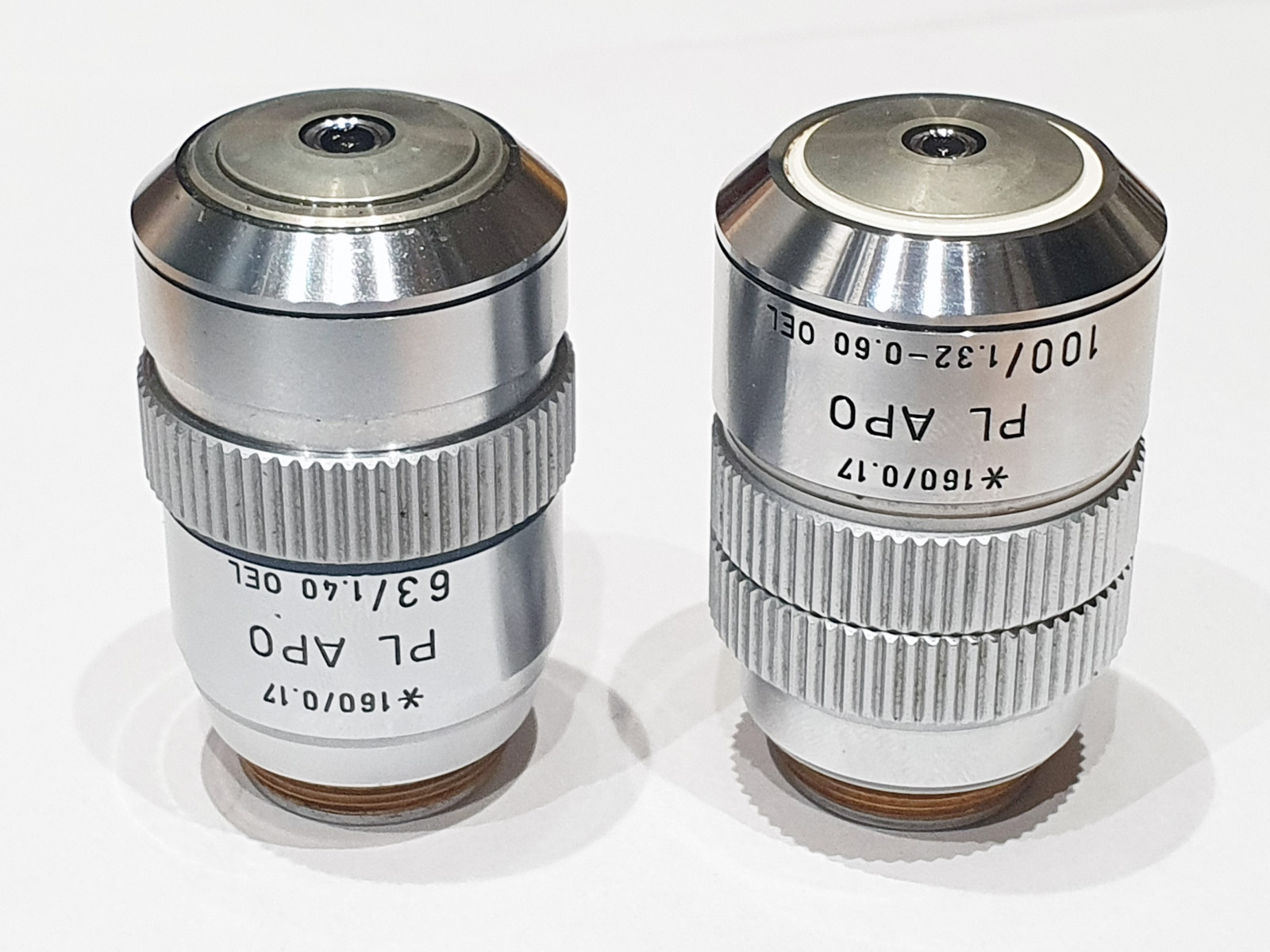
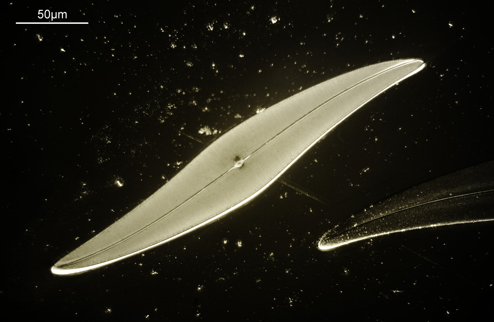
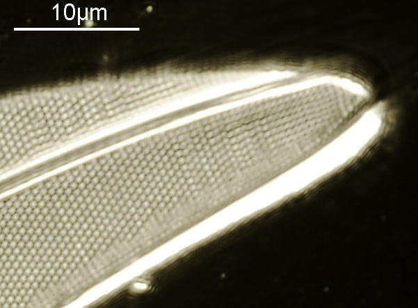
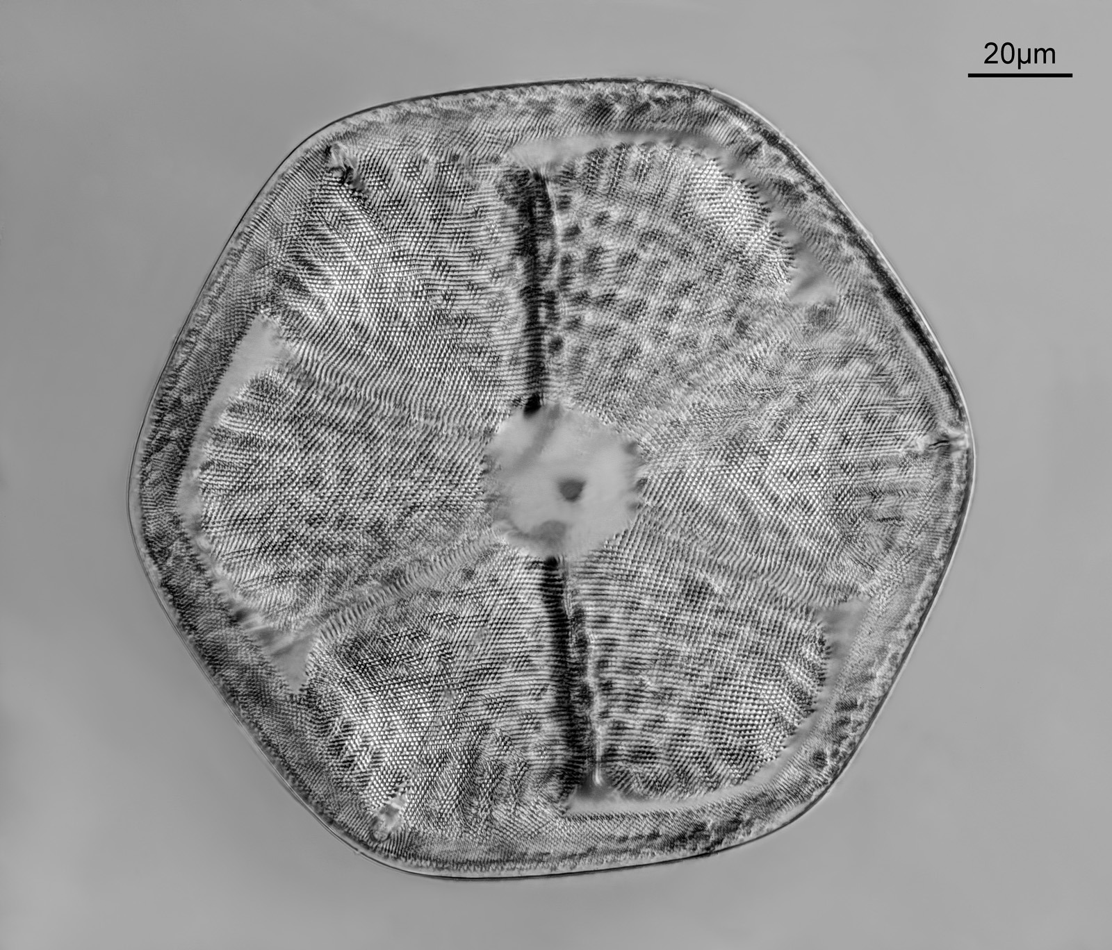
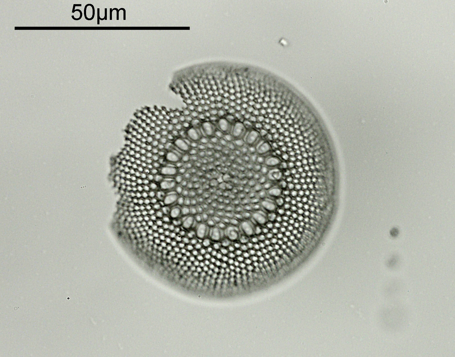
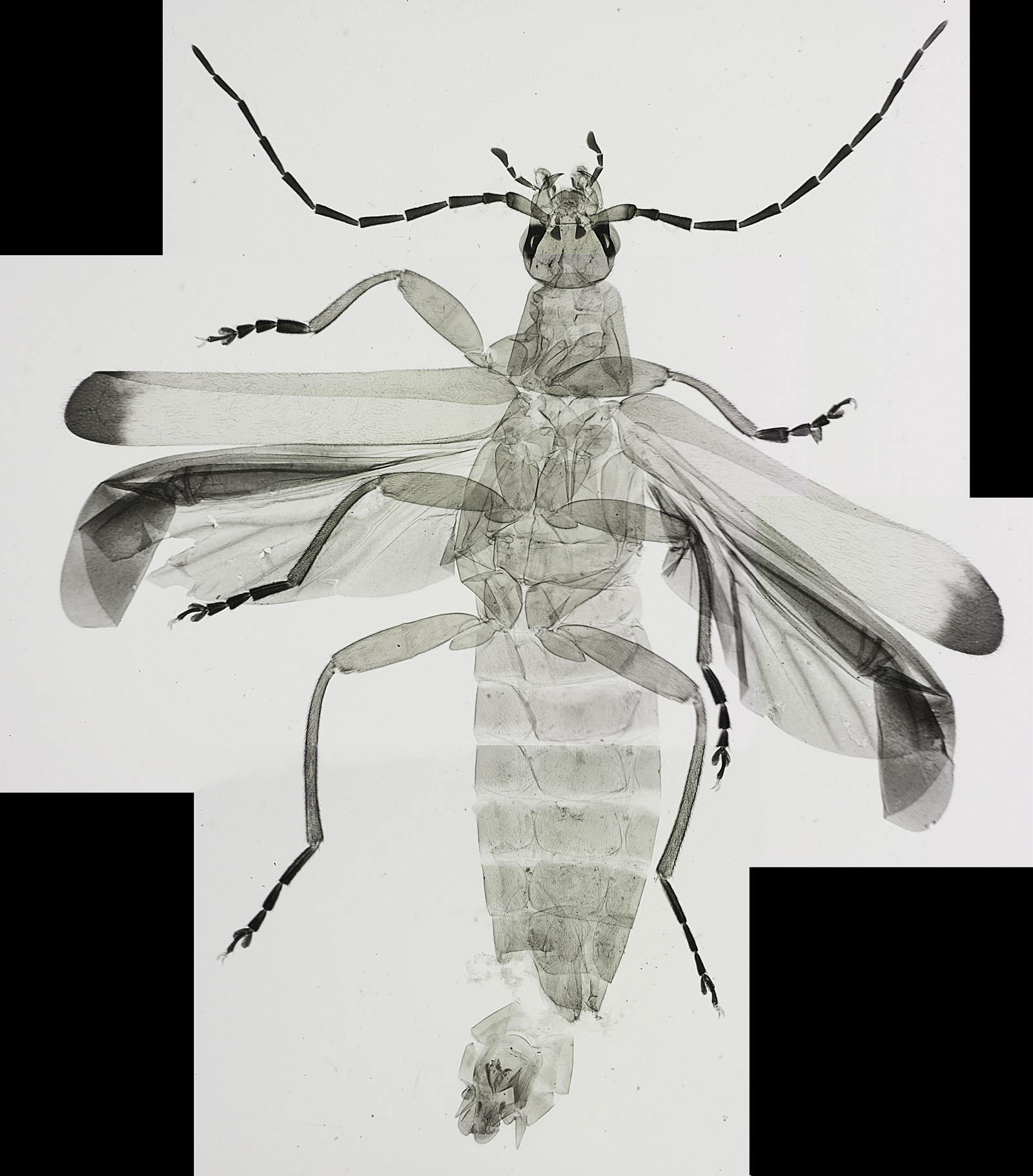
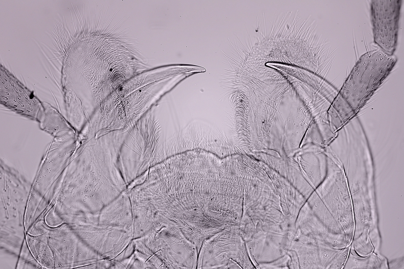
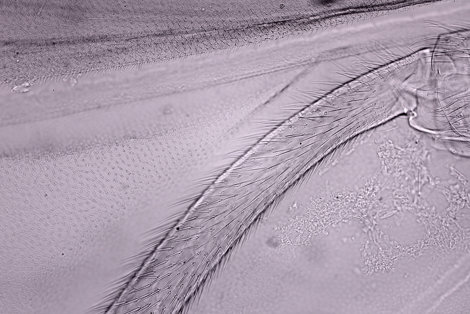
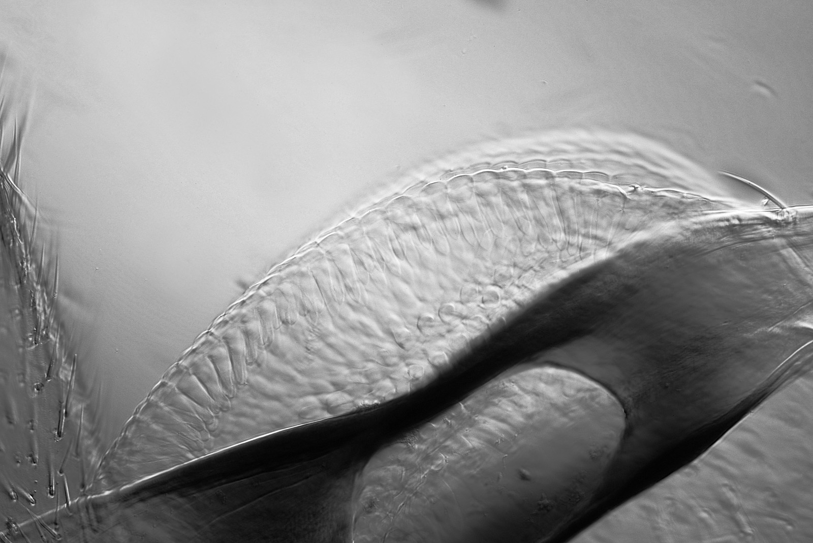
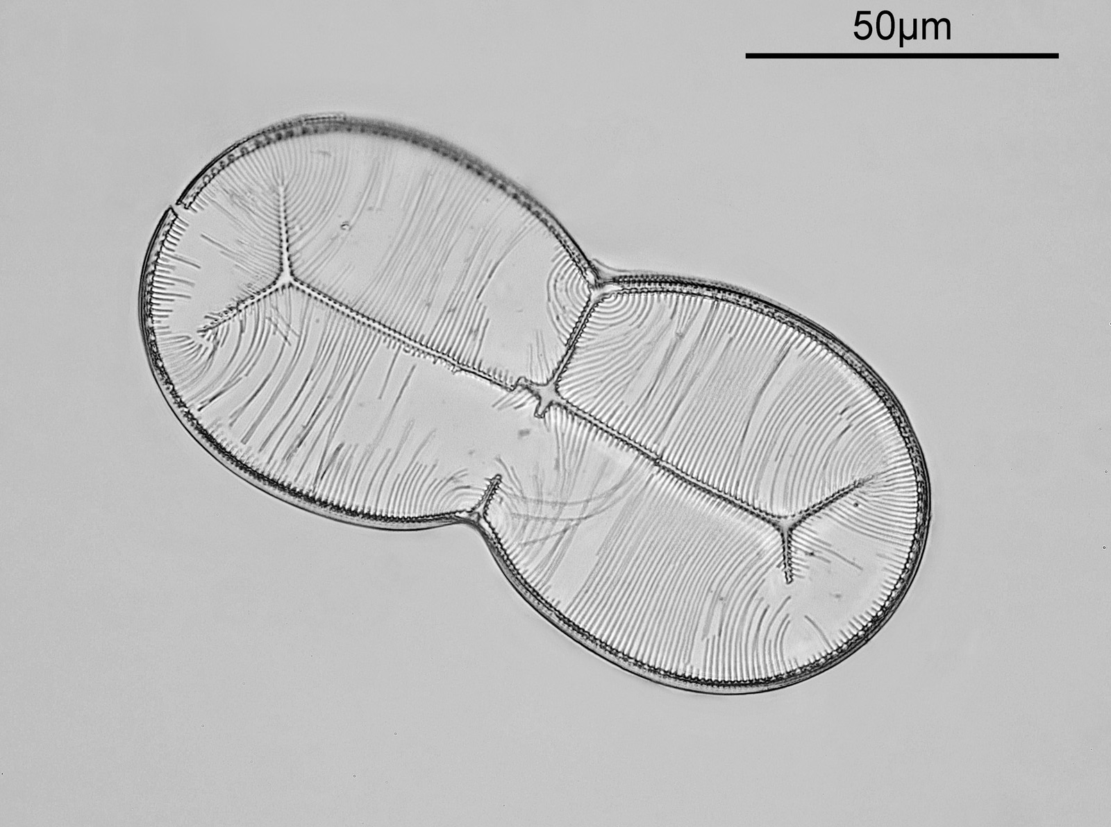
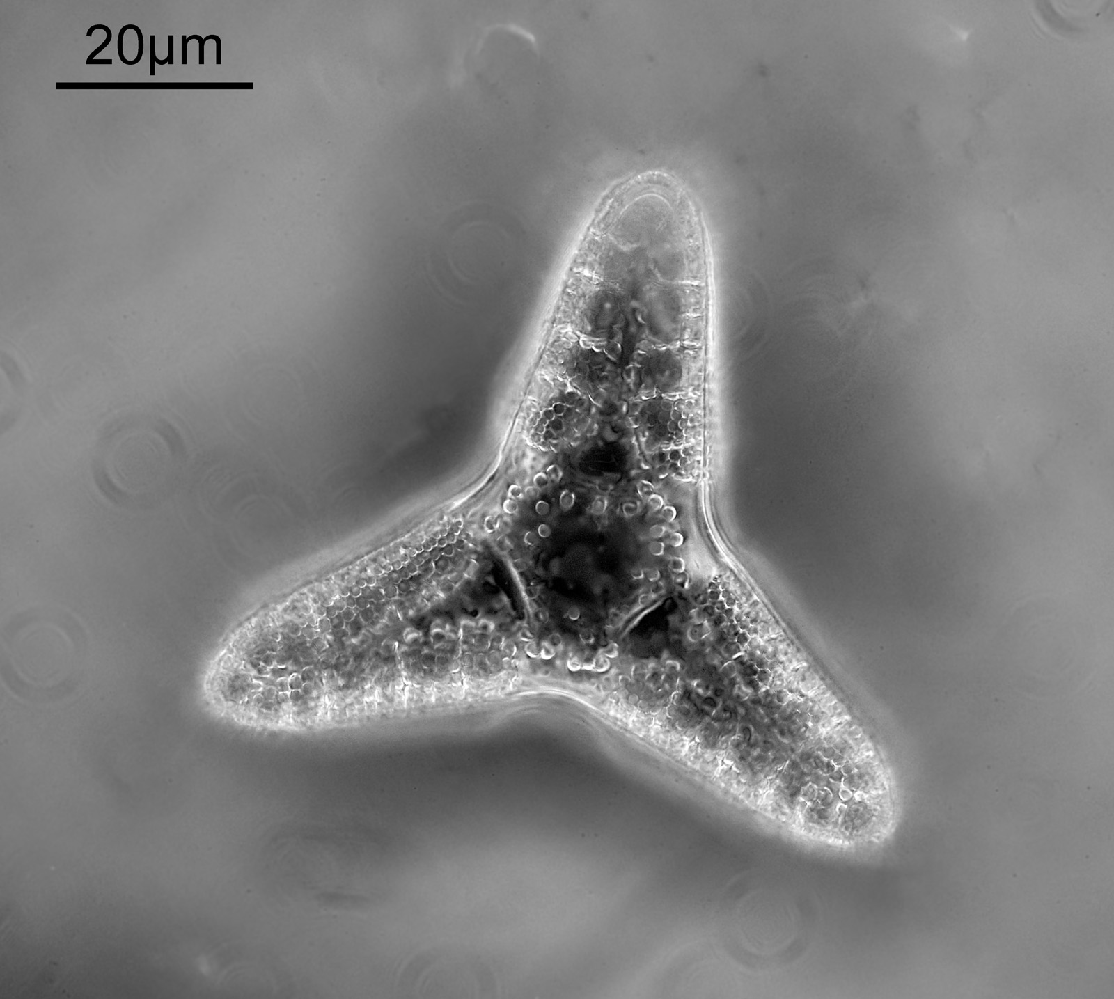
The microscope images today come from a Triceratium nitescens slide by the maker R.I. Firth. The slide is marked as ‘Barbados’ and ‘Very rare’, is mounted in Styrax and was made in 1943. There is a single example of the diatom on the slide. The microscope used was my modified Olympus BHB. The condenser was an Olympus Aplanat Achromat, set to slightly oblique and oiled to the underside of the slide. The objective was a 63x Leitz Pl Apo NA 1.40, oiled to the top of the slide. The photoeyepiece was a 2.5x Nikon CF. Lighting was 450nm LED (white LED source with a Thorlabs 450nm, 40nm bandpass filter). 17 images were stacked in Zerene stacker. Camera was a monochrome converted Nikon d850 done by MaxMax. The image has been reduced in resolution for sharing here, although a crop of the main image at original resolution is also shared. Here’s the final image.
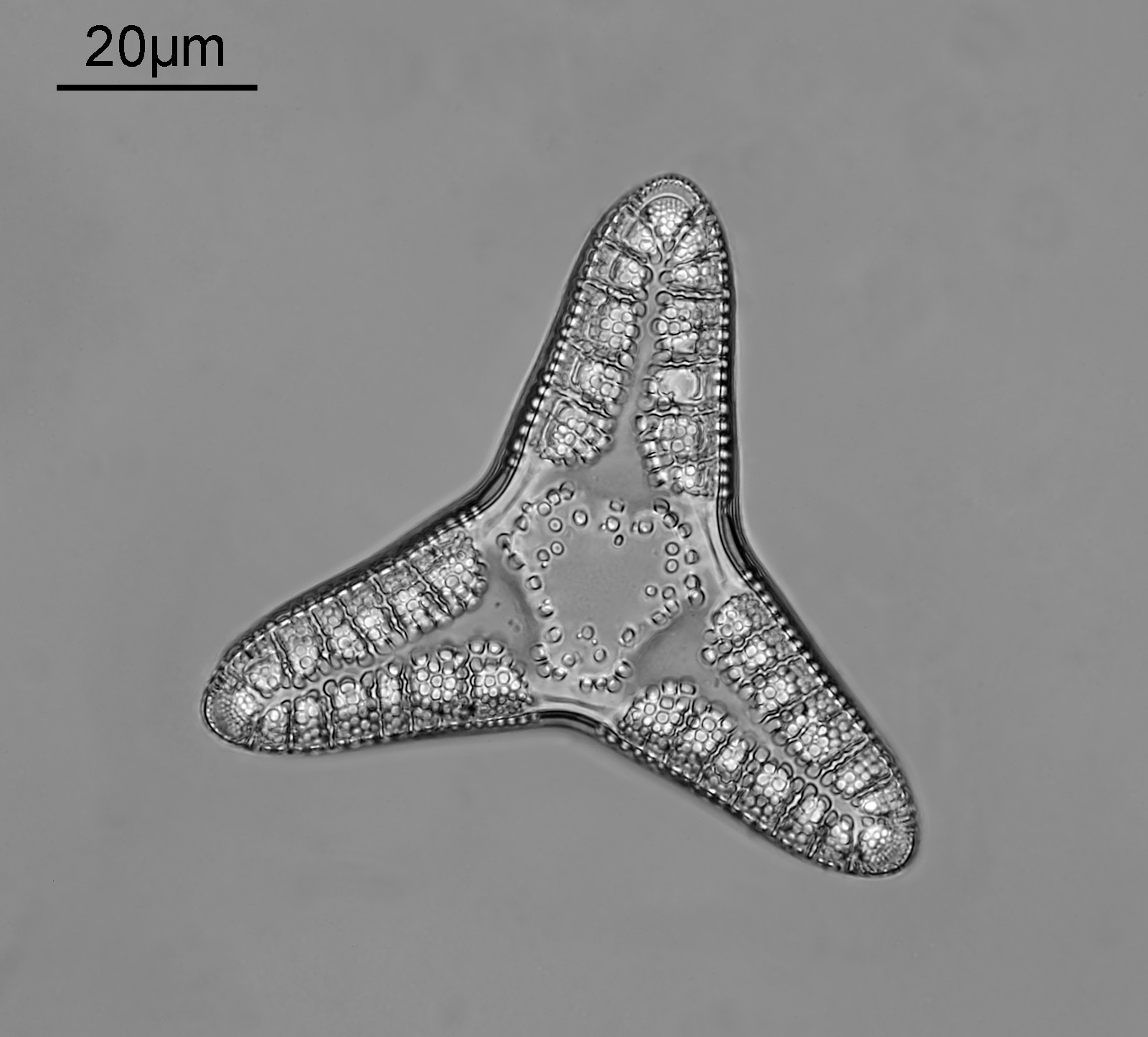
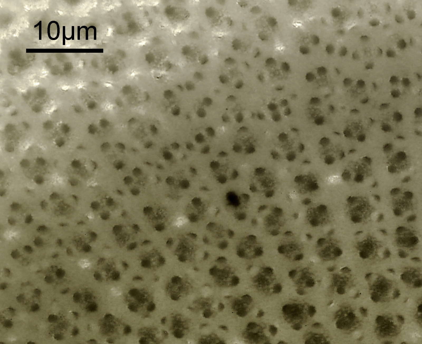
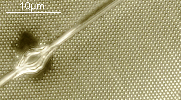
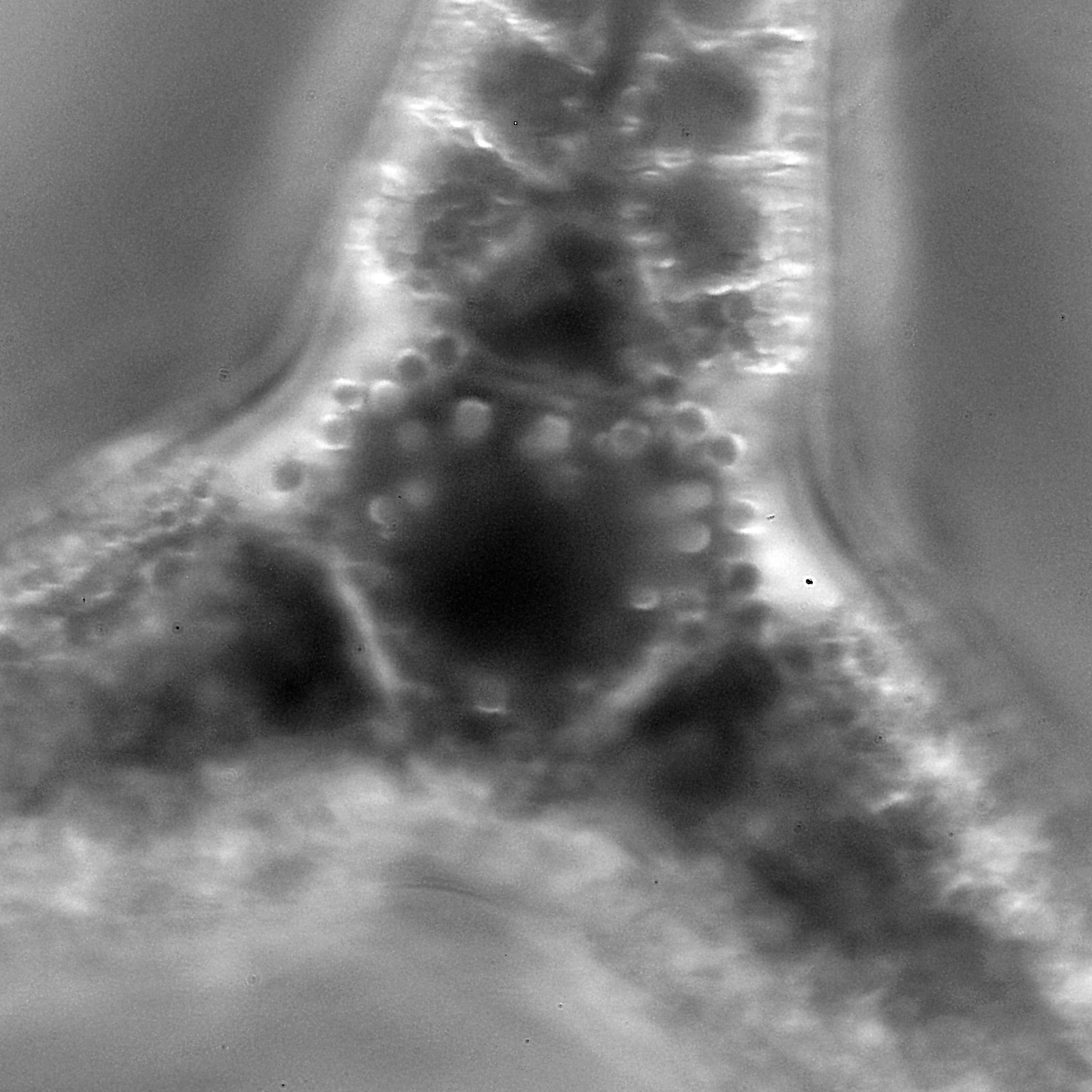
And a crop of the image shown at original pixel resolution.
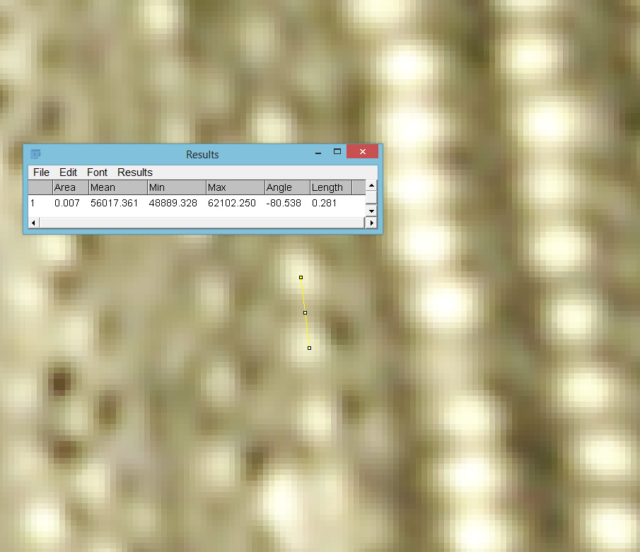
A friend asked me about why I do stacking, and it reminded me that I have written something which briefly covered the reason before (see here). Essentially though, at high magnifications with high NA objectives, the depth of field of a single image is tiny – way less than a micron in the setup used here – making it impossible to get the whole diatom in focus in a single photograph. So I take multiple photos, moving the stage very slightly between each one, and then stack them together using software called Zerene which takes the in focus parts of each image and combines them. Live view on the camera is very helpful here, as I can see what is in focus with each image and make the movements accordingly to capture everything. After stacking, the image still need some cleaning up which I do in Photoshop – making the background smoother, and removing artifacts from dirt on the sensor coverglass. Microscopy will reveal dirt that you never knew was there before in normal photography – the shorter the wavelength of light used, and higher the objective NA, the smaller the features that will be revealed and will need editing out. I tend to capture my images in the camera as Jpeg files, and after stacking output the stack a 16 bit Tiff for subsequent work (outputting the stack as a Jpeg gave me more artifacts especially in the background of the image). Ideally I would do everything as Tiff files, but my computer is old and stacking Jpeg files is a tough enough job for it.
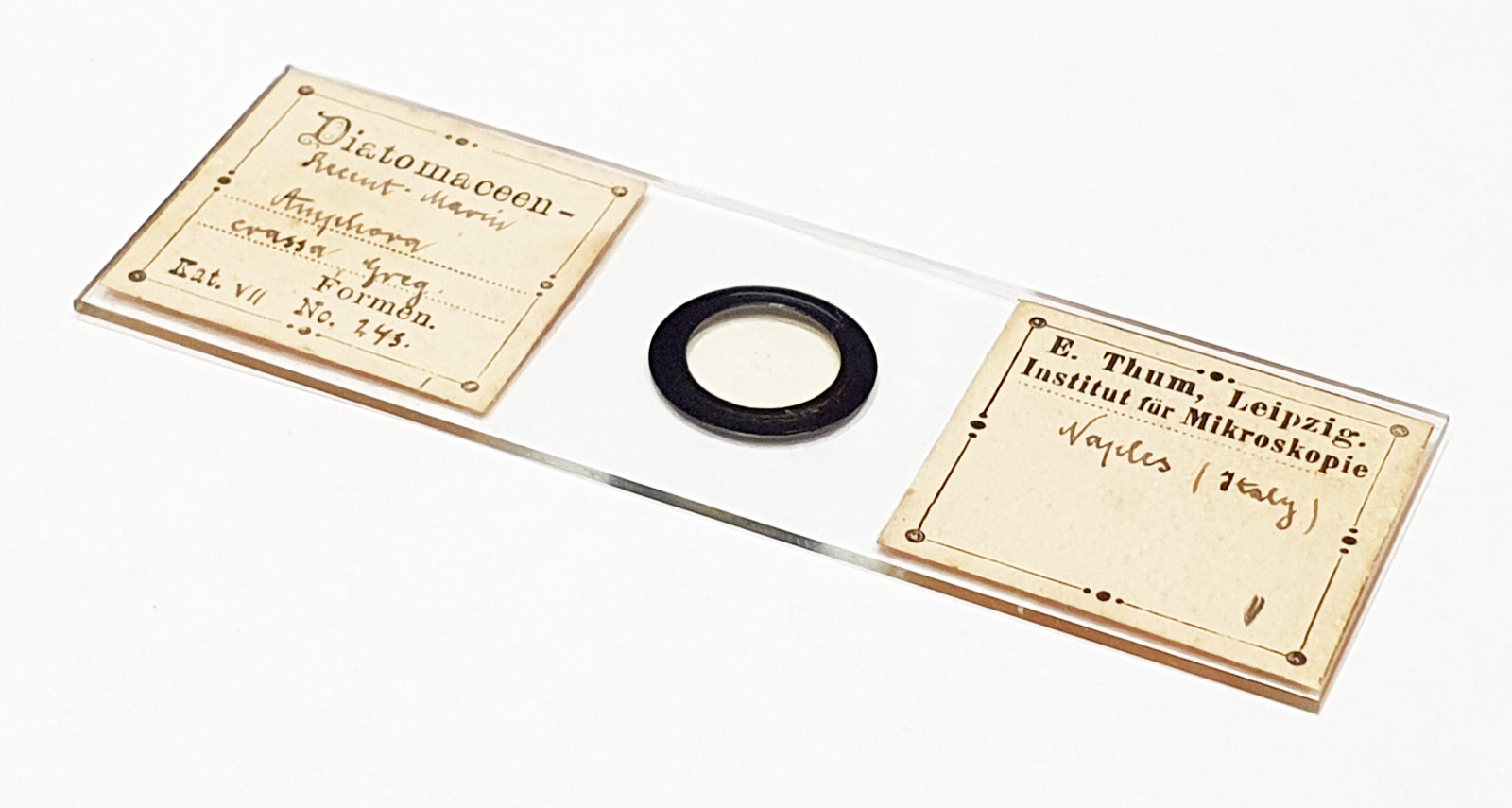
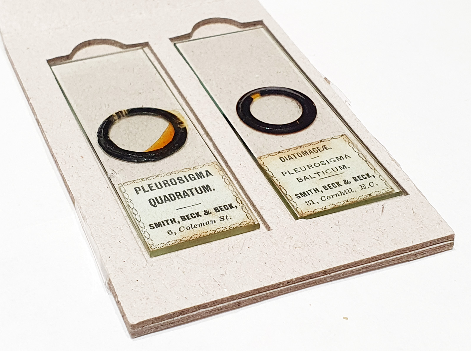
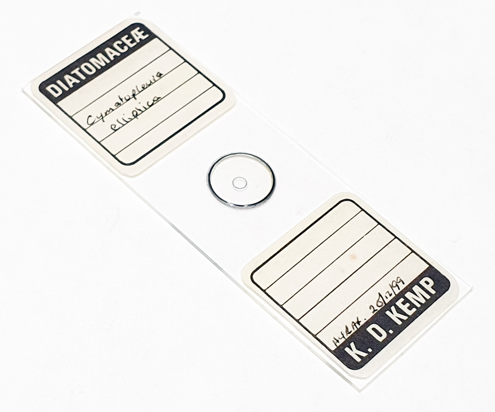
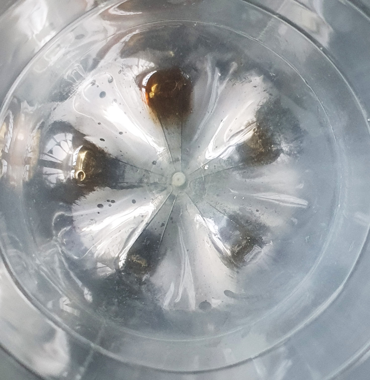
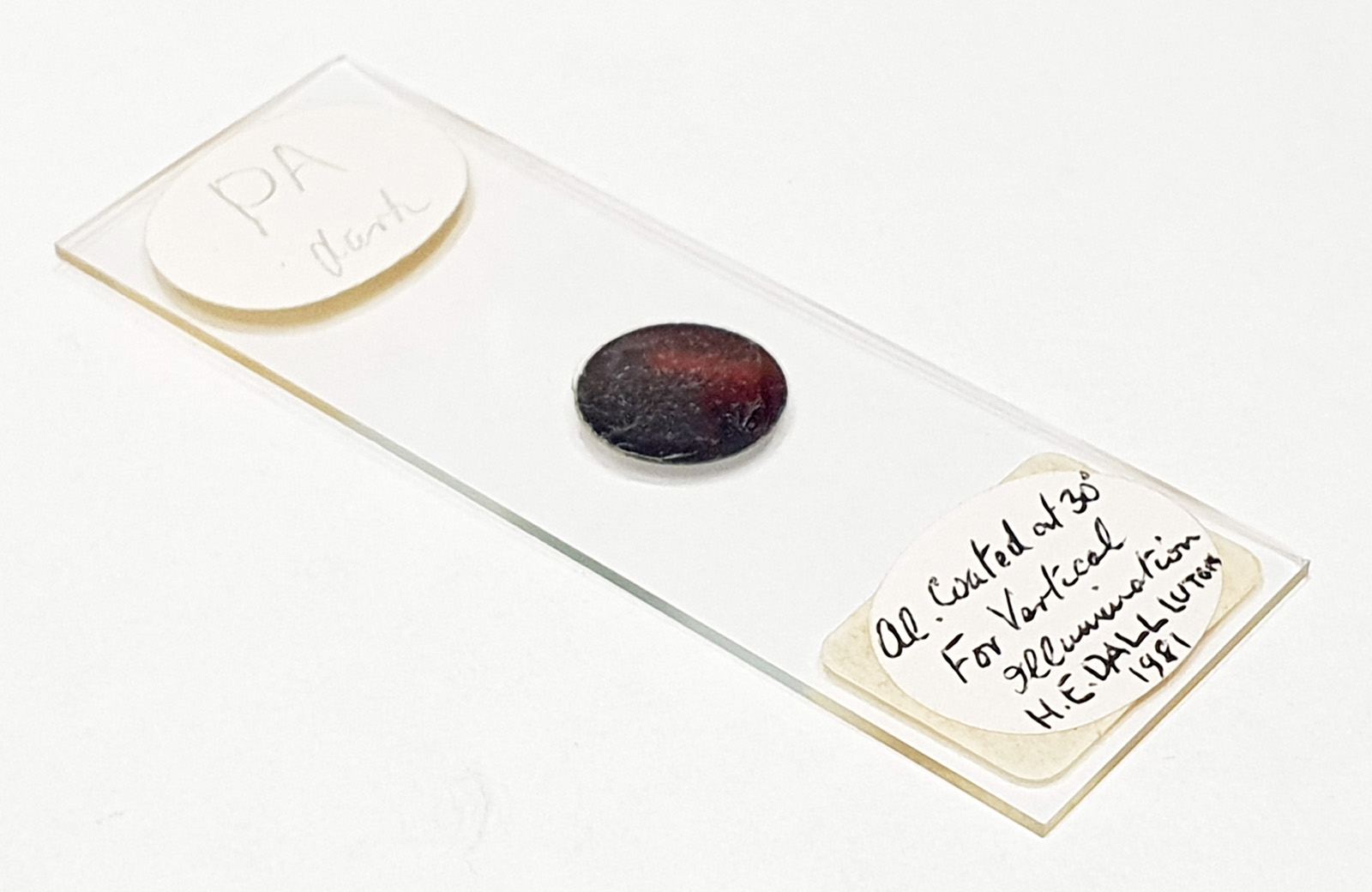
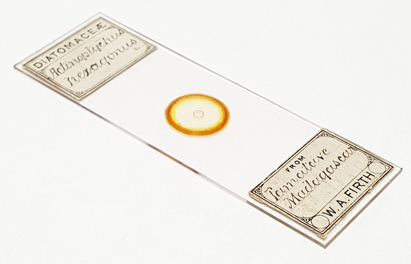
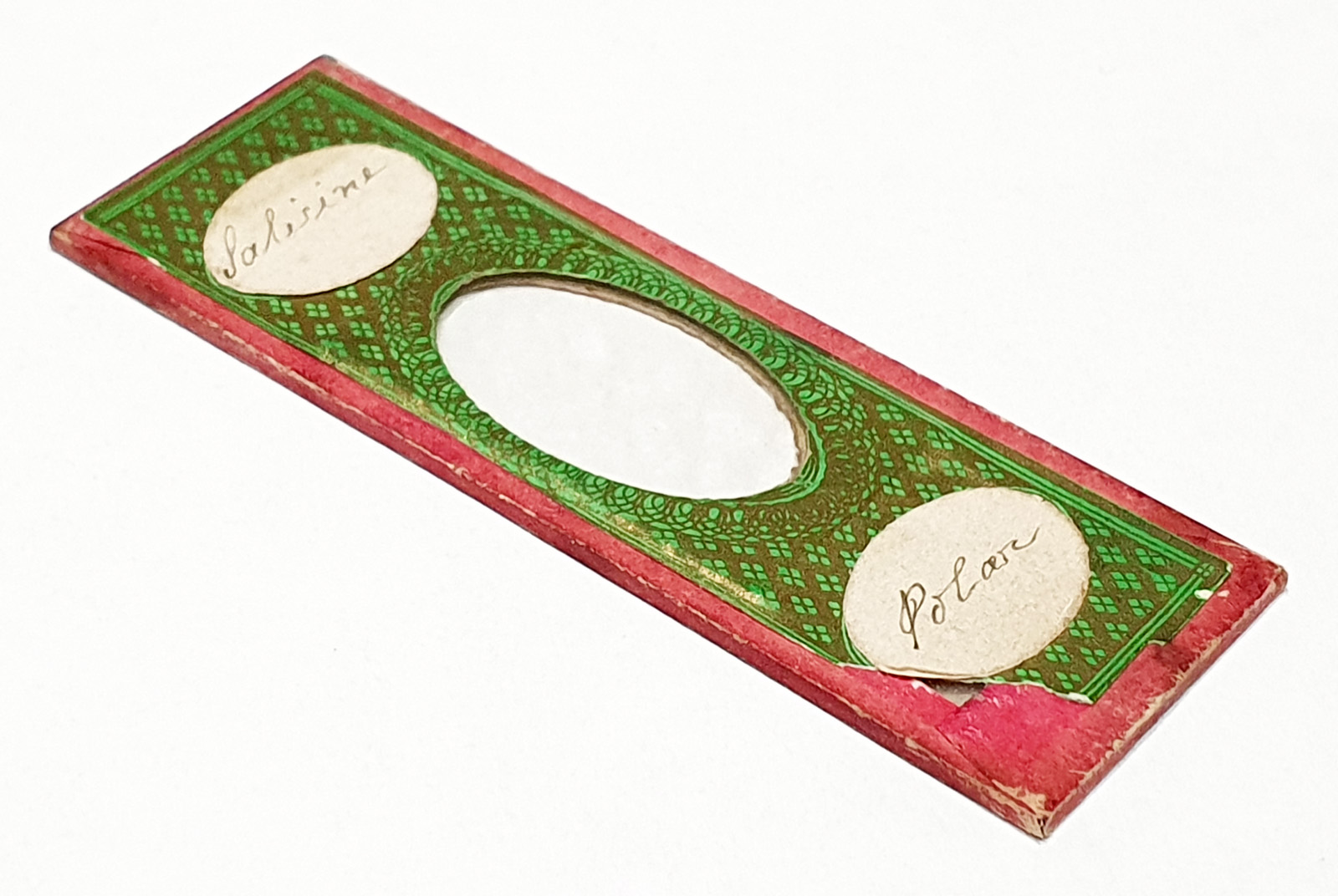
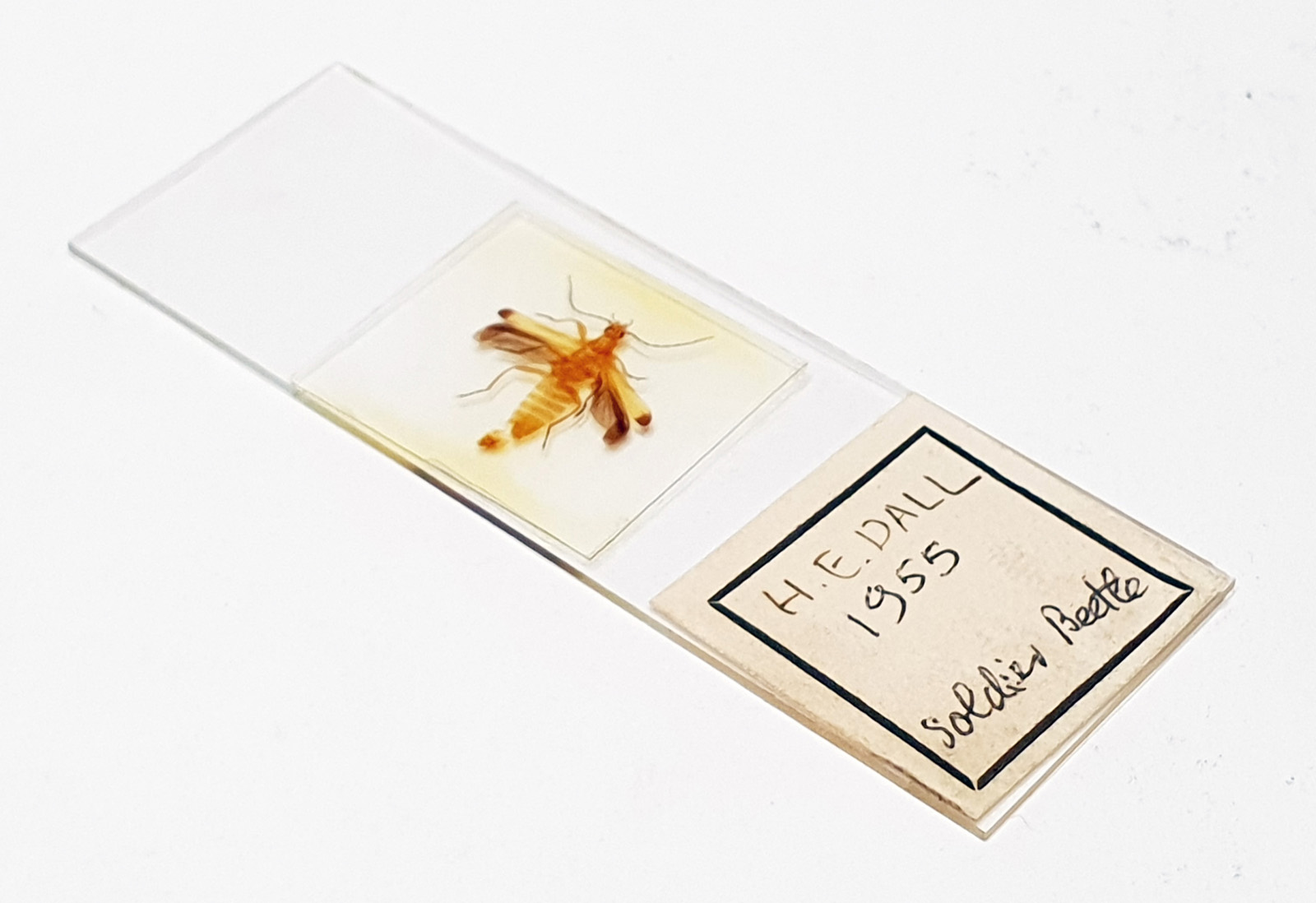
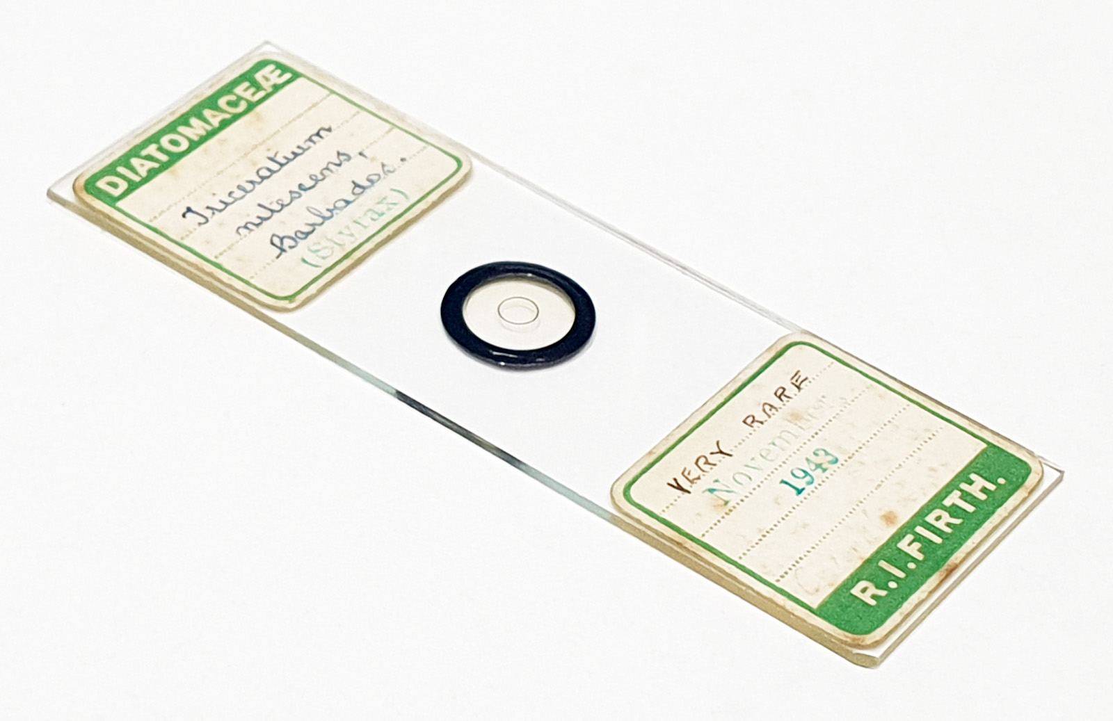
Before I go to cover some UV work I did with this slide, here is the slide itself.
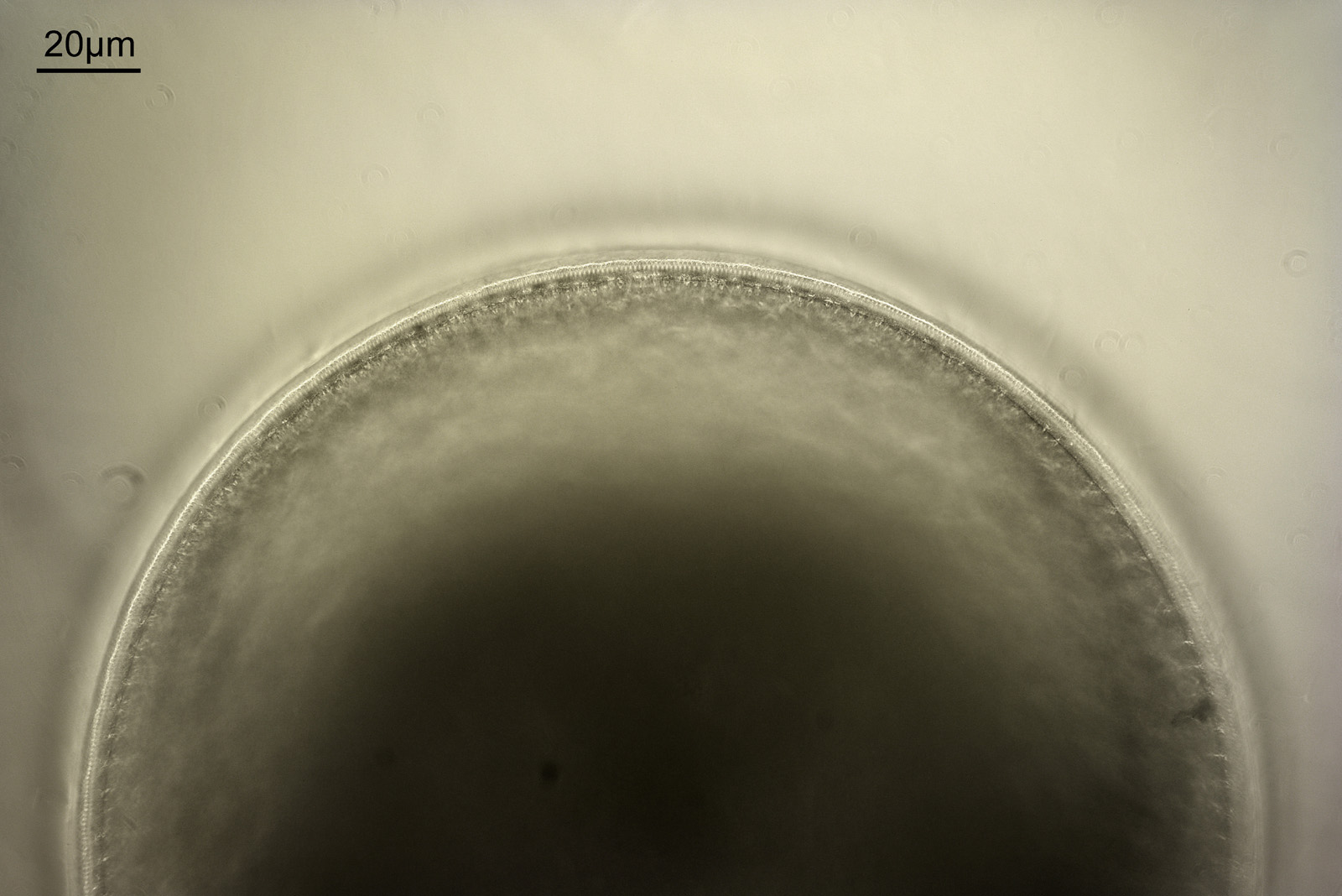
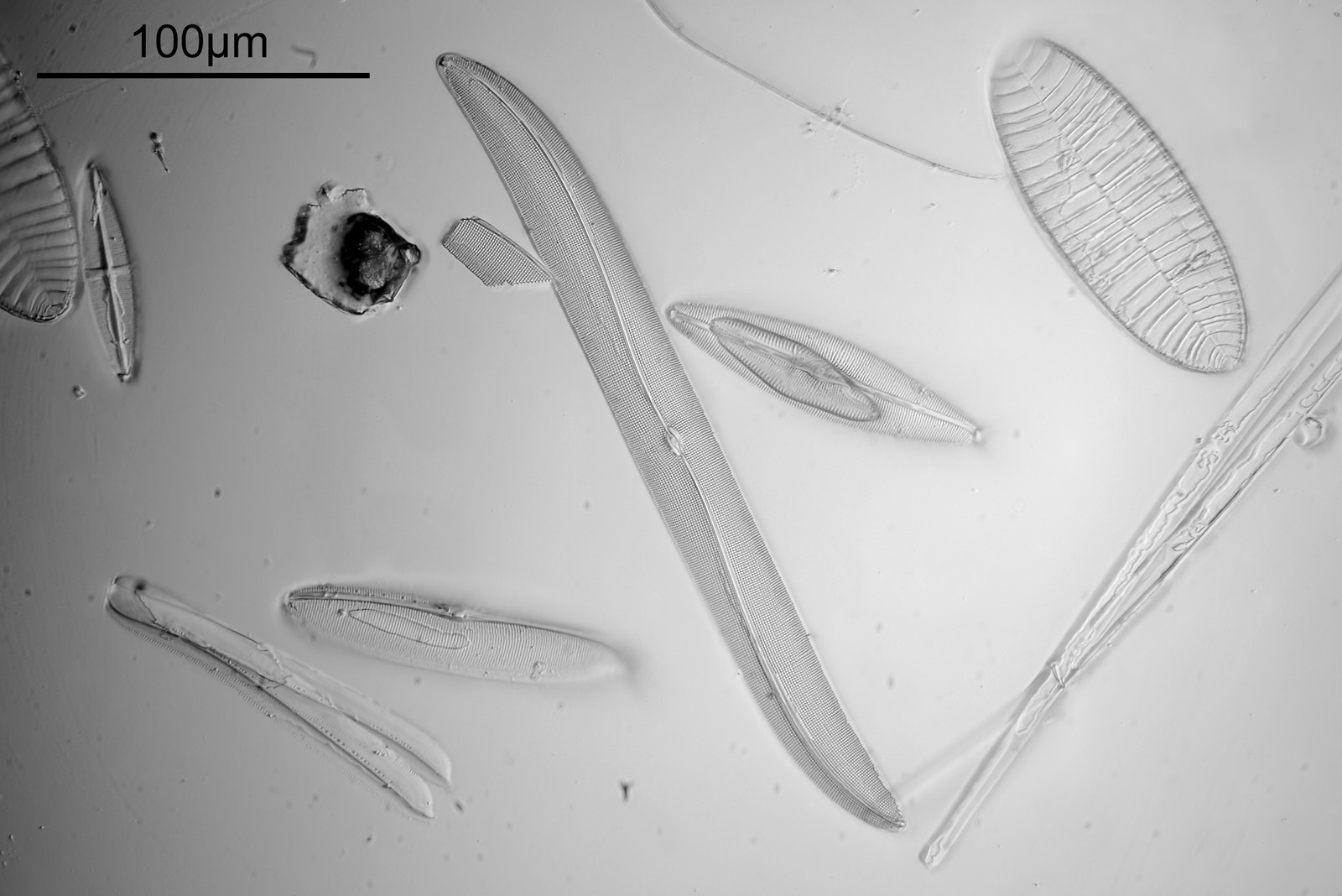
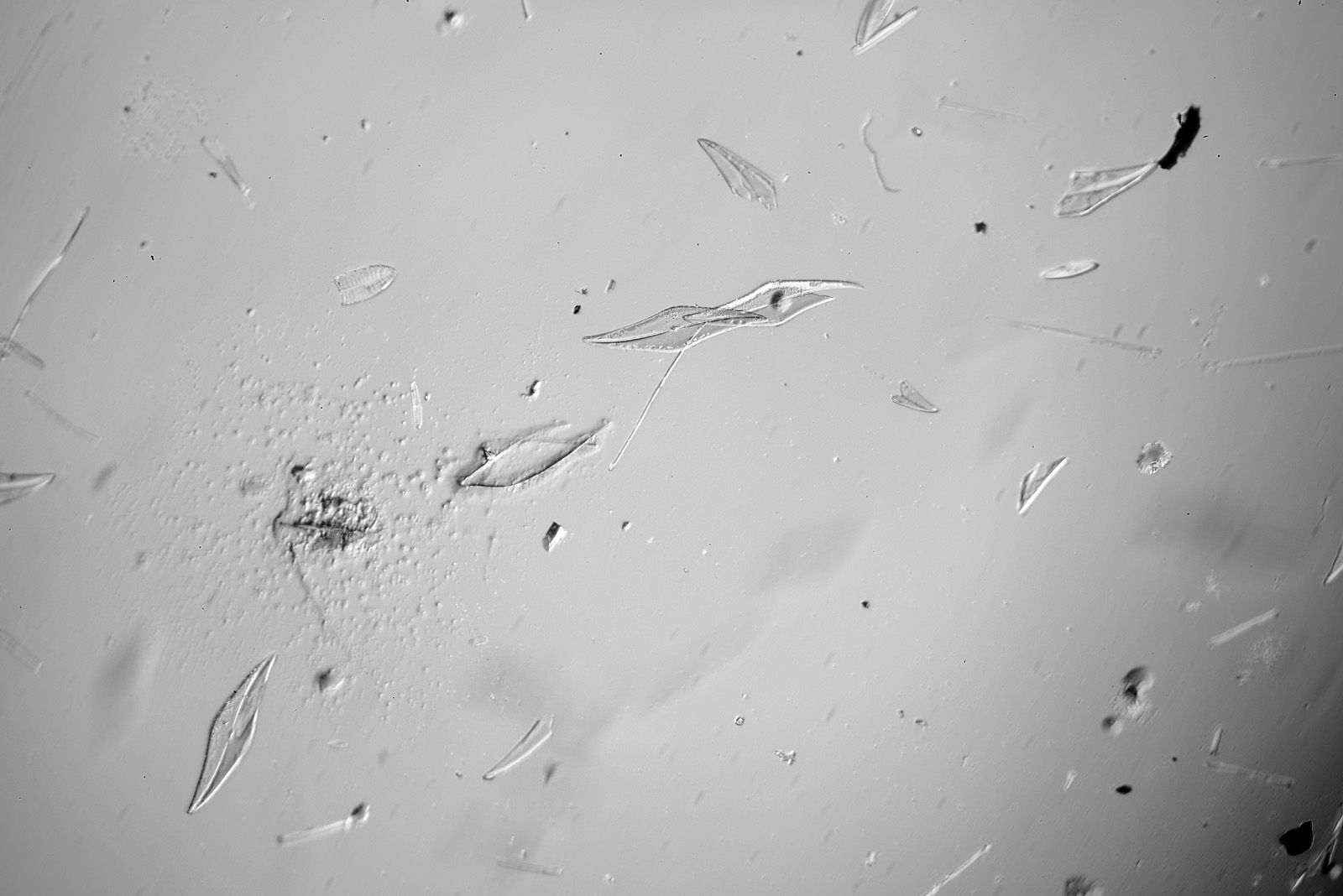
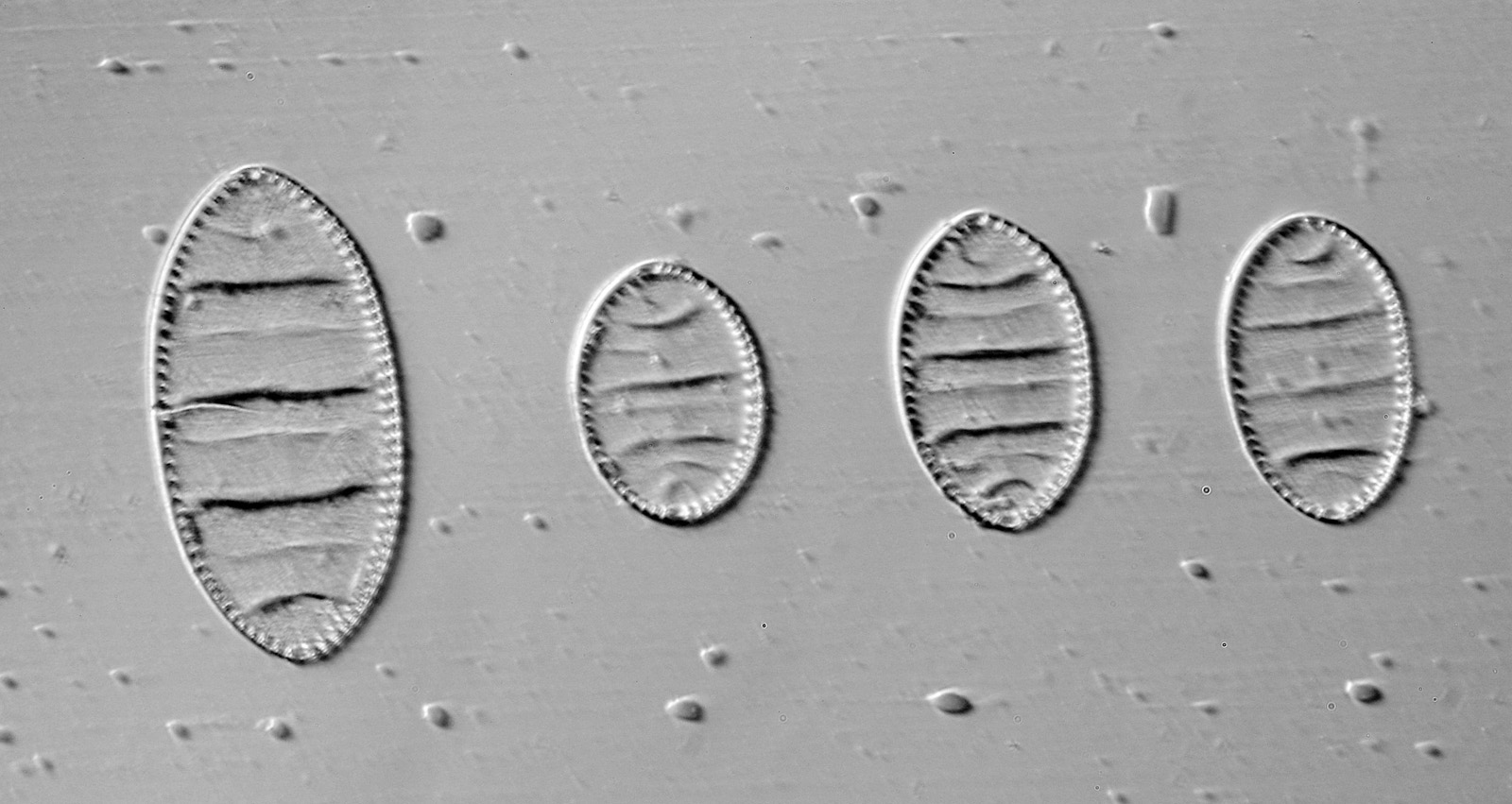
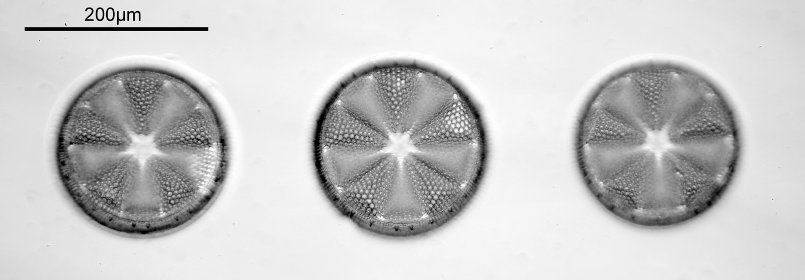
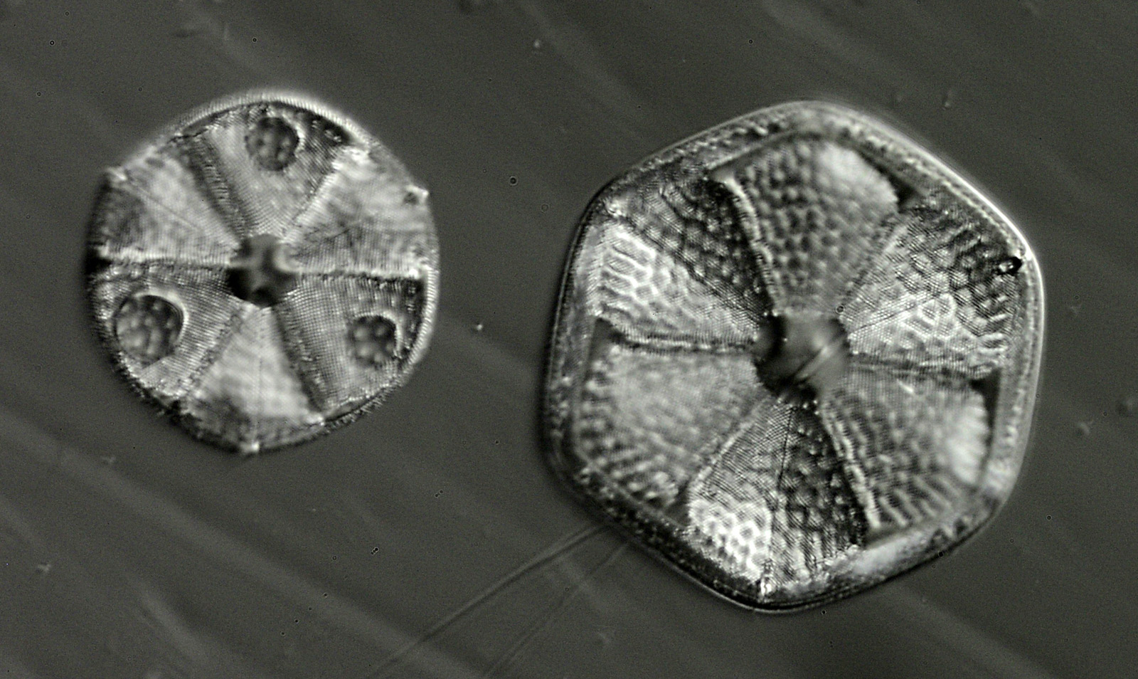
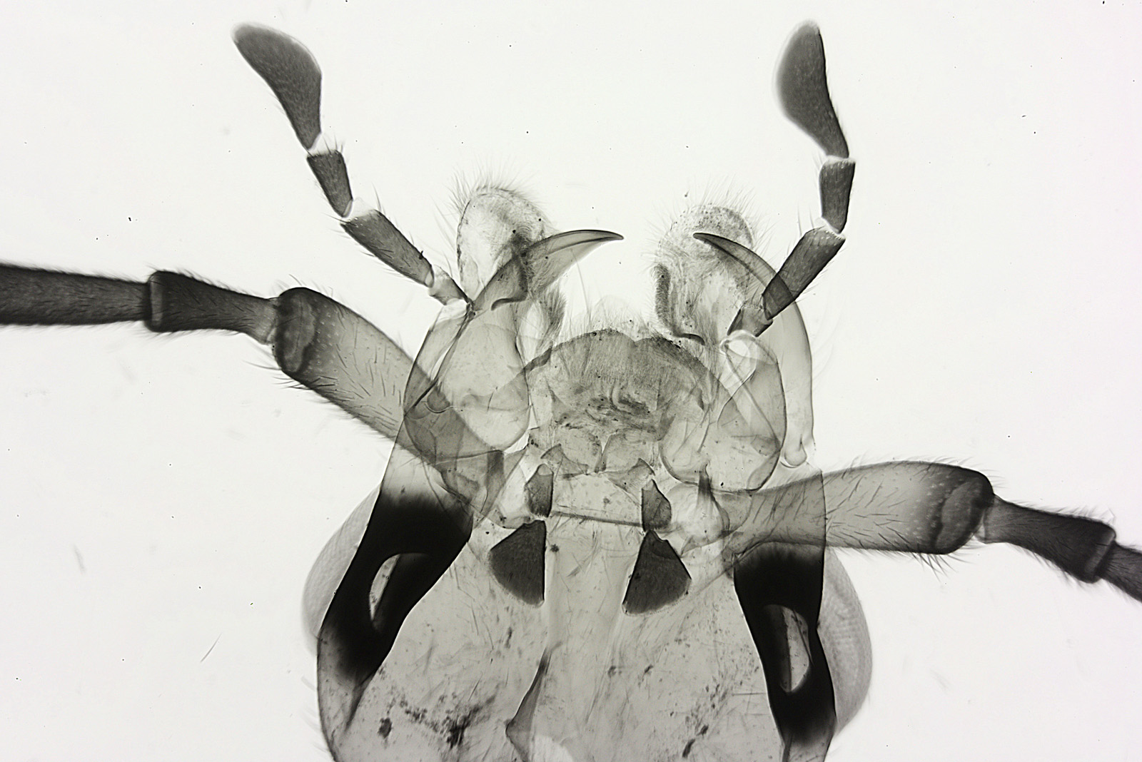
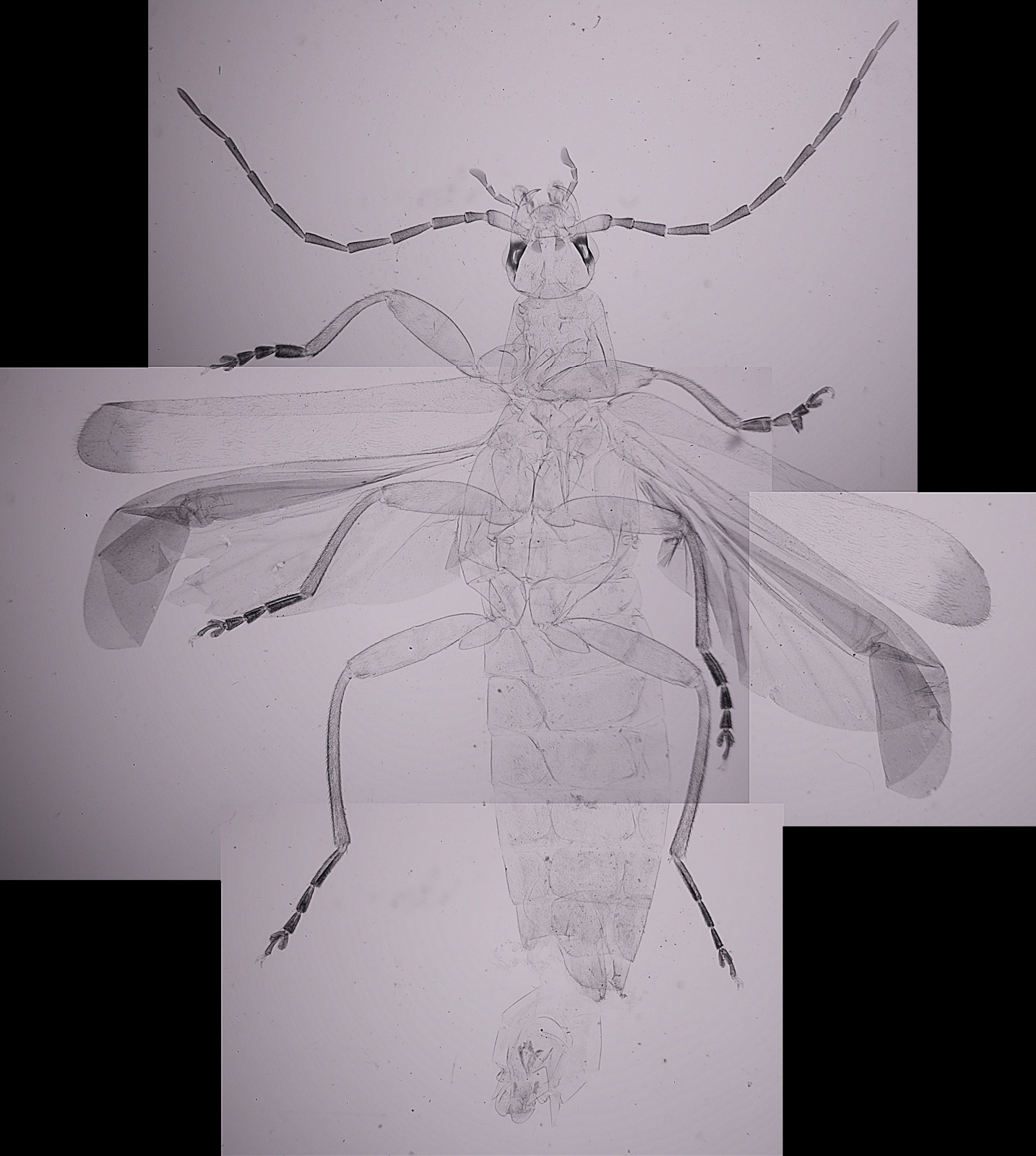
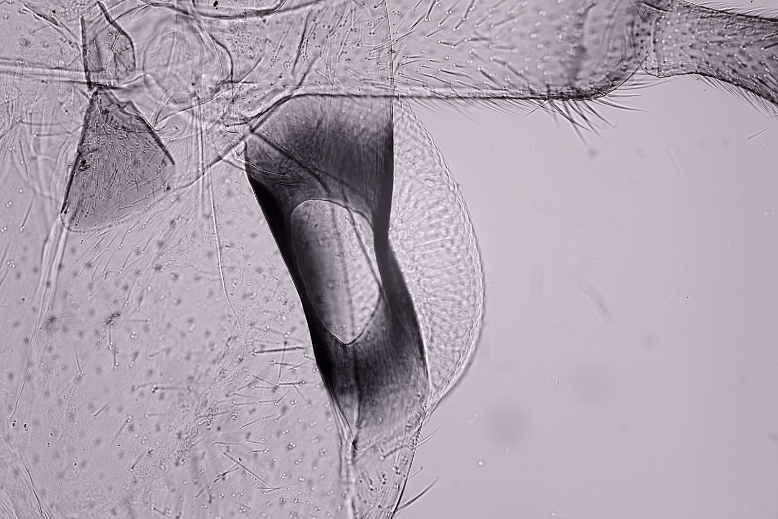
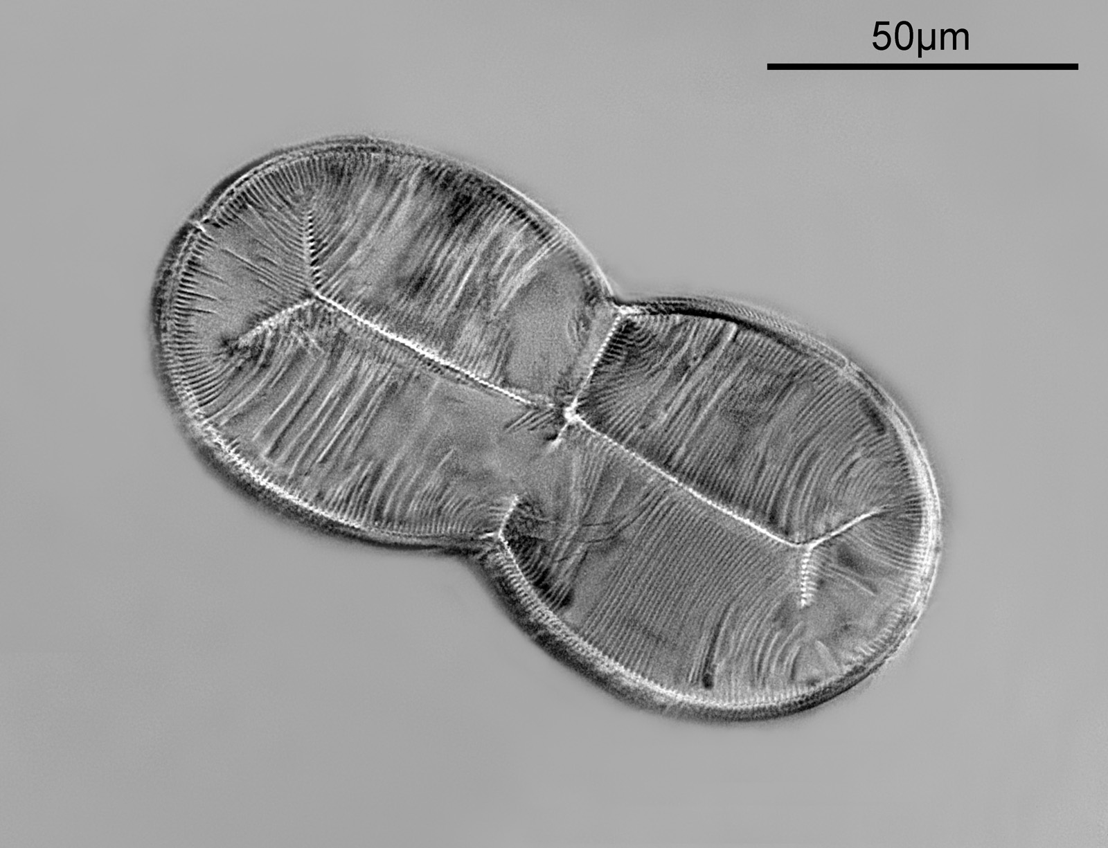
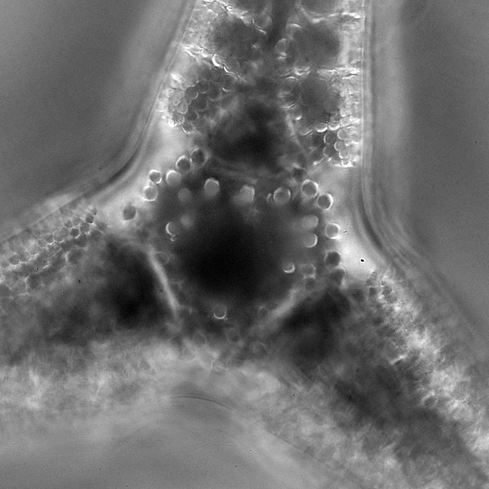
While the slide was on the microscope, I also did some experiments with 365nm UV (the camera is monochrome converted and sensitive to UV, visible and IR light). Keeping the same objective, the condenser was swapped for a Watson Quartz Cassegrain (which I just realised I’ve not written about before so must rectify that), the light source was a 365nm LED torch, and I filtered the light going to the camera by a stack of 2 Edmund Optics 365nm, 10nm bandpass filters. Here’s a photo of the diatom made up from a stack of 4 images with this setup.
The effect wasn’t quite what I was after, but I think it still looks nice and shows the features in a different way. Given the high NA of the objective the effect is produce circular oblique lighting when using the Watson Quartz Cassegrain condenser.
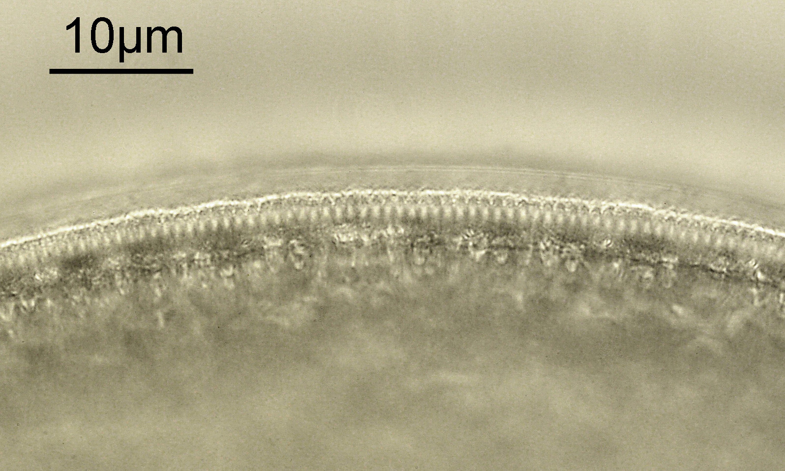
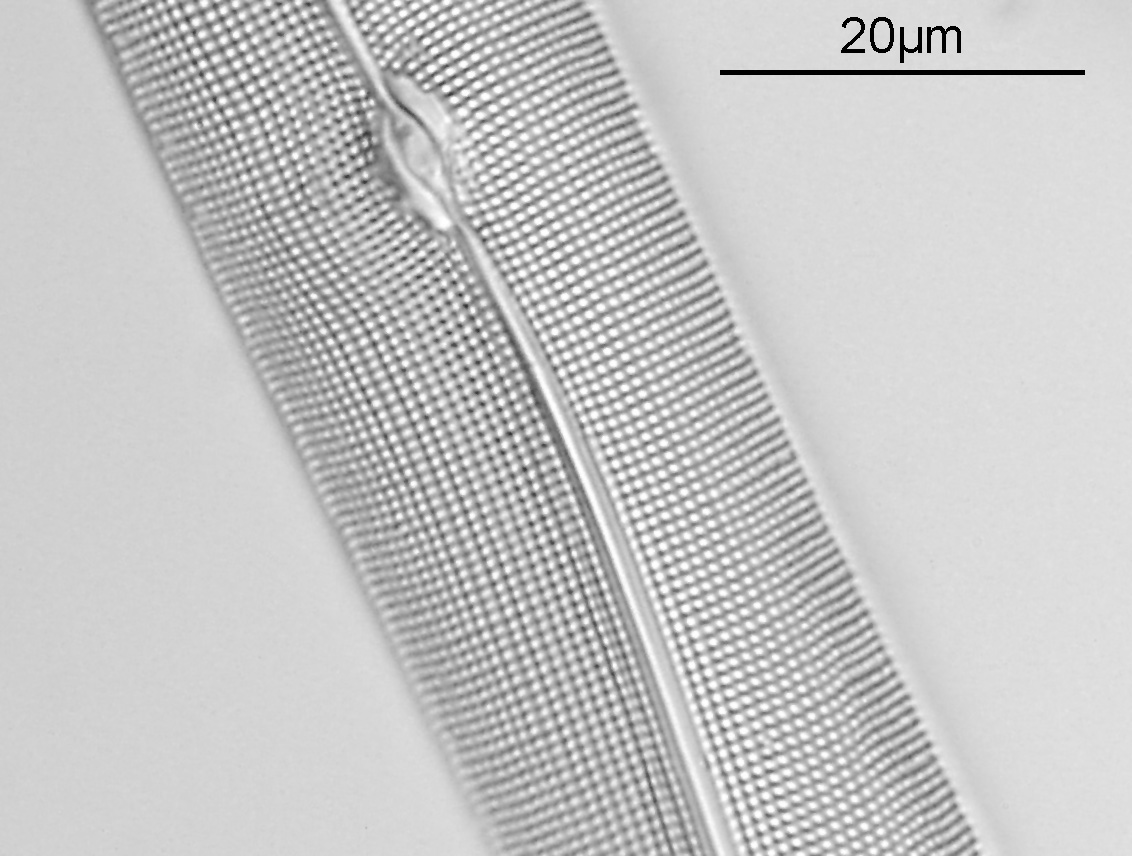
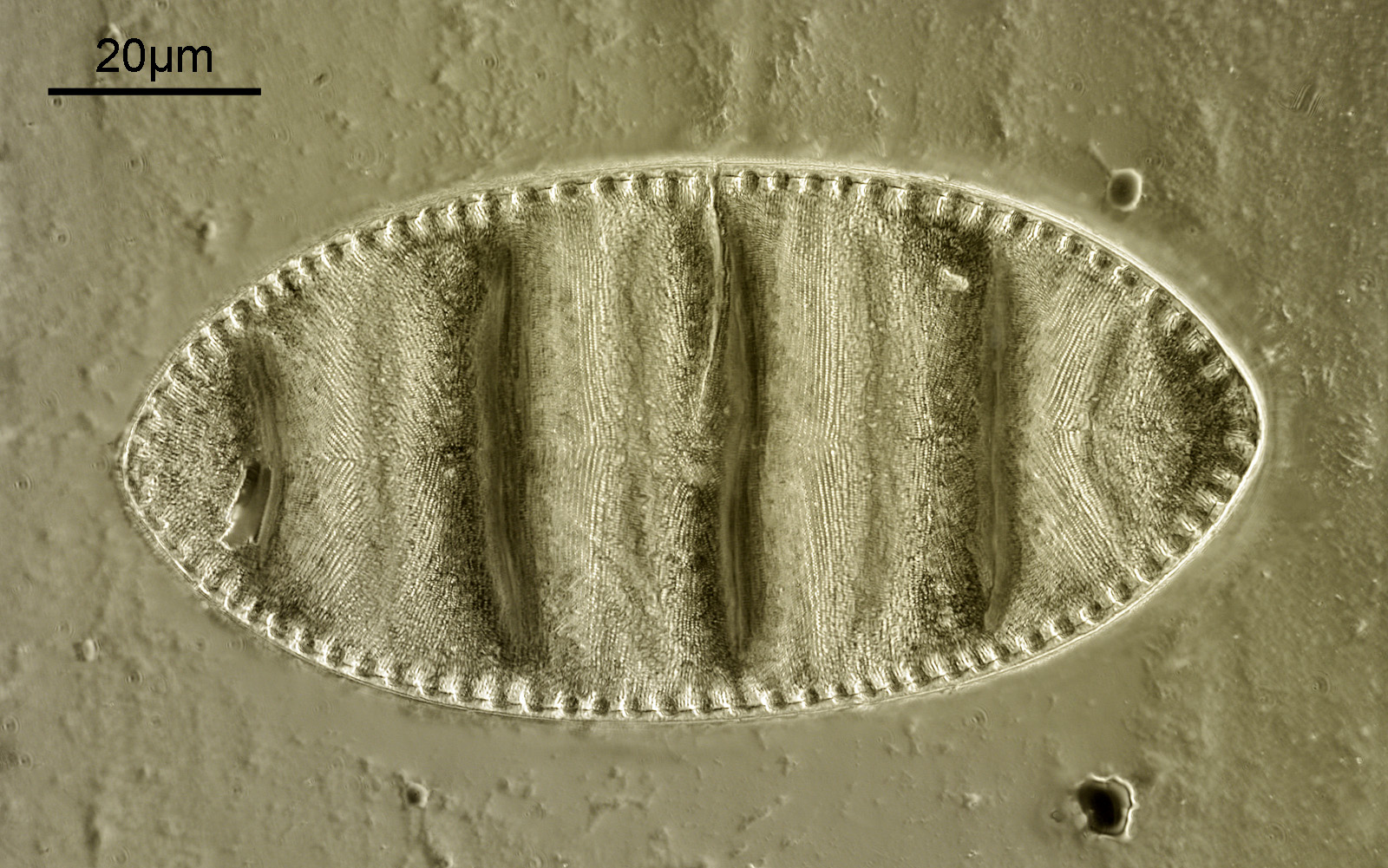
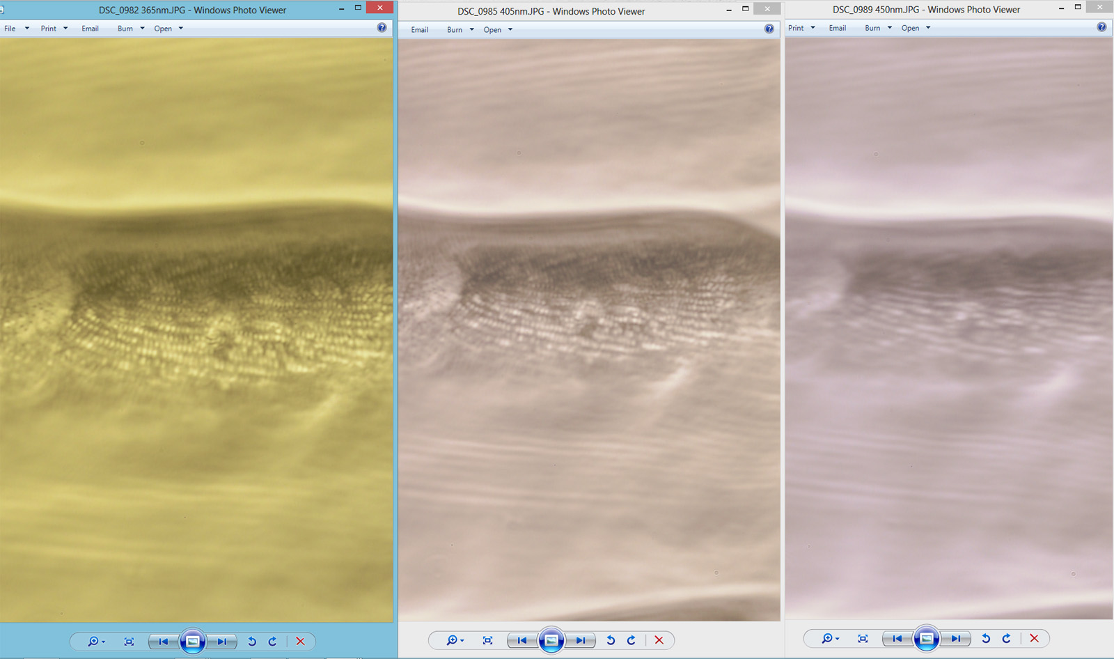
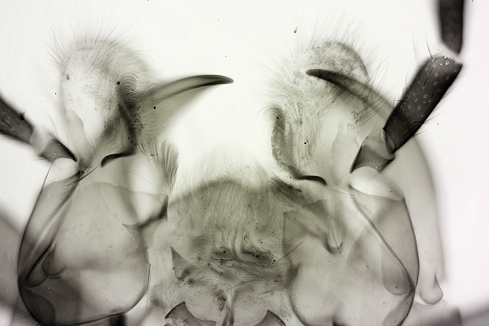
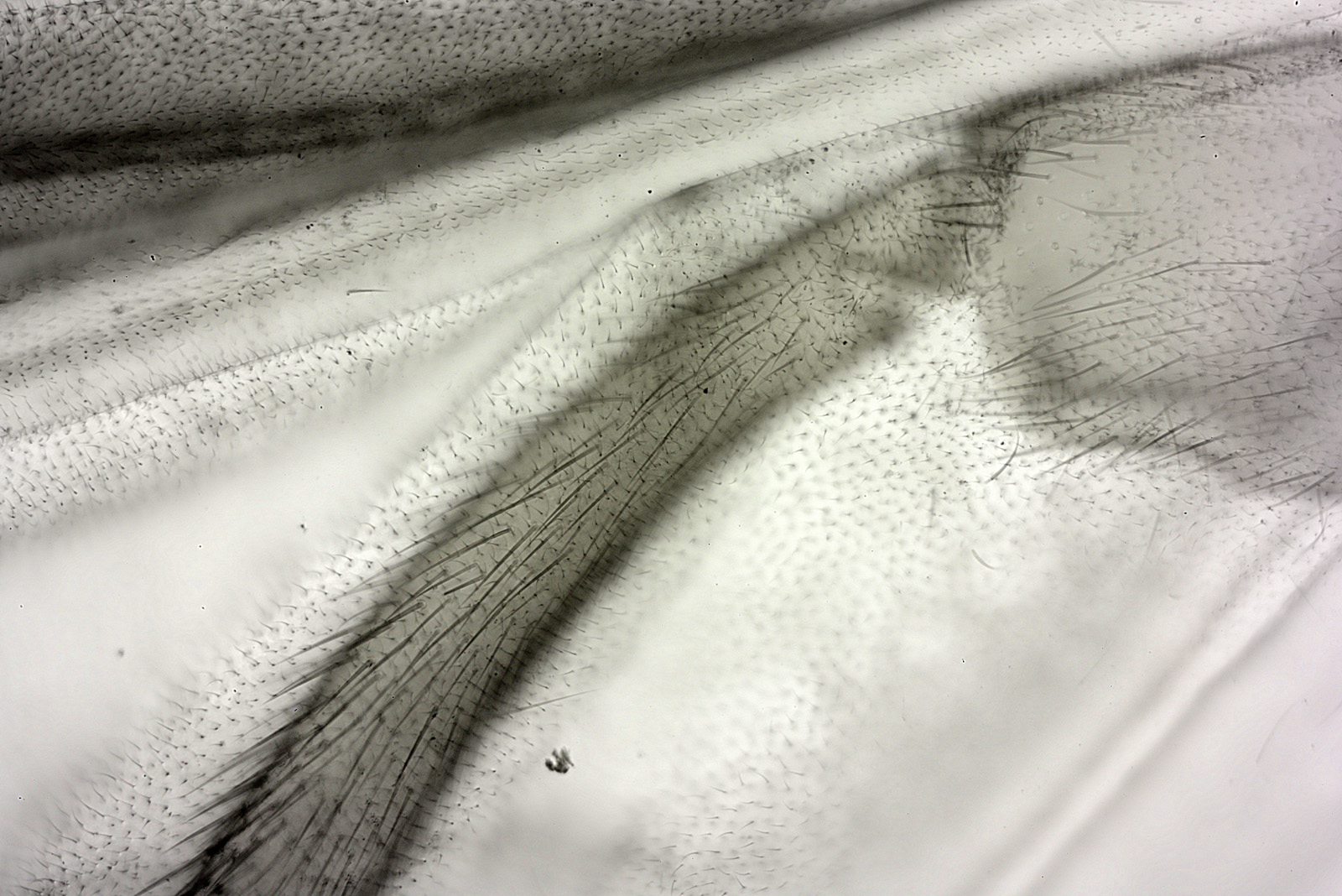
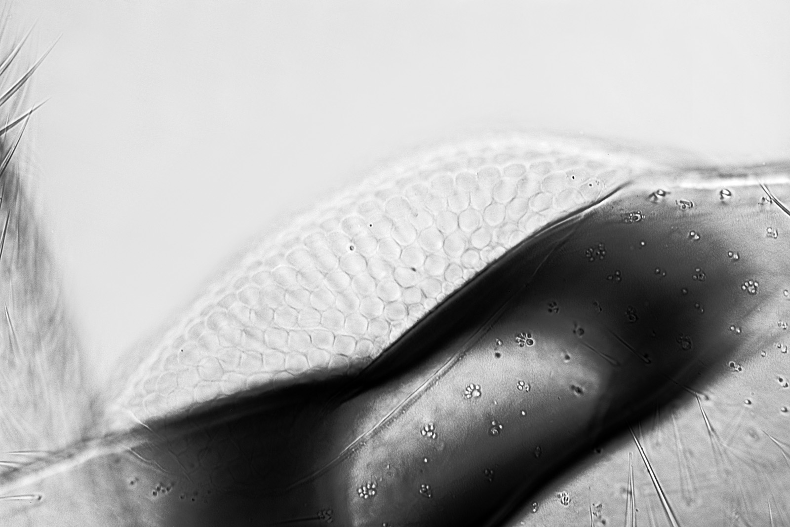
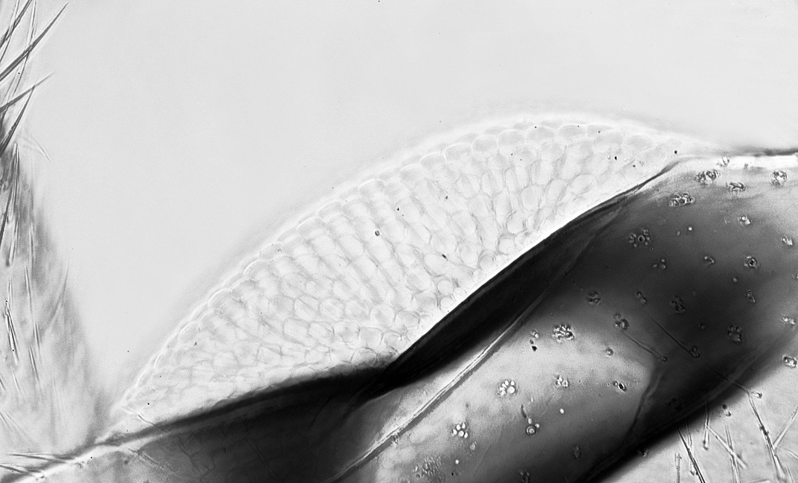
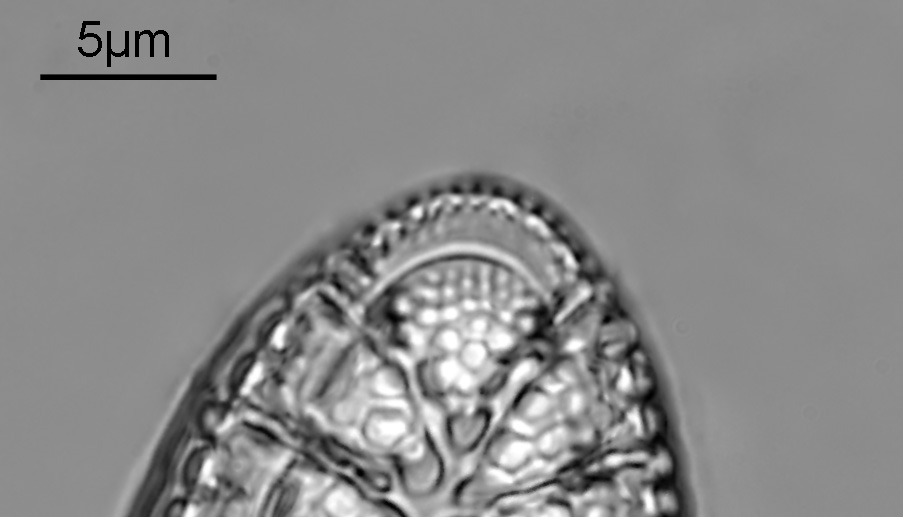
Before I go, one last thing to mention, when dealing with what is effectively extreme macro imaging on the microscope, the settings under which the images are taken can have a huge impact on the quality of the final photograph. I use 3s exposure delay and electronic front curtain shutter, but found out something yesterday which is worth sharing. Initially I tried ‘S’ (Single shot) and the image was quite blurry. I changed to ‘Mup’ (Mirror up) and the image was much sharper. Comparison below using 365nm LED light, crops shown at original pixel resolution.
I tried this a few times, and got the same result each time, so will be using Mup from now on with the d850. I seem to recall Nikon changed how they deal with Mup with the d850 so it can now be used with live view unlike earlier Nikon cameras, so perhaps it is a d850 specific consideration.
Slightly longer post than usual today, but I thought it would be useful to cover off some other things in addition to showing the main image. As always, thanks for reading, and if you’d like to know more about my work I can be reached here.