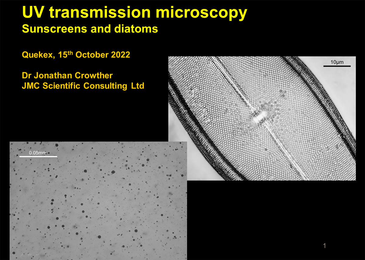
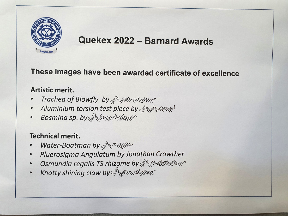
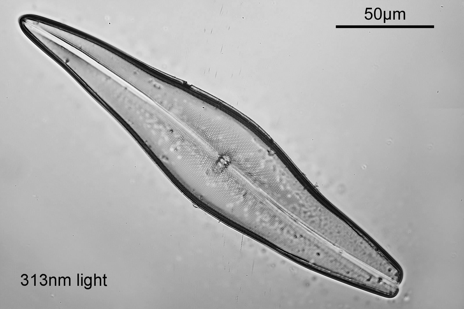
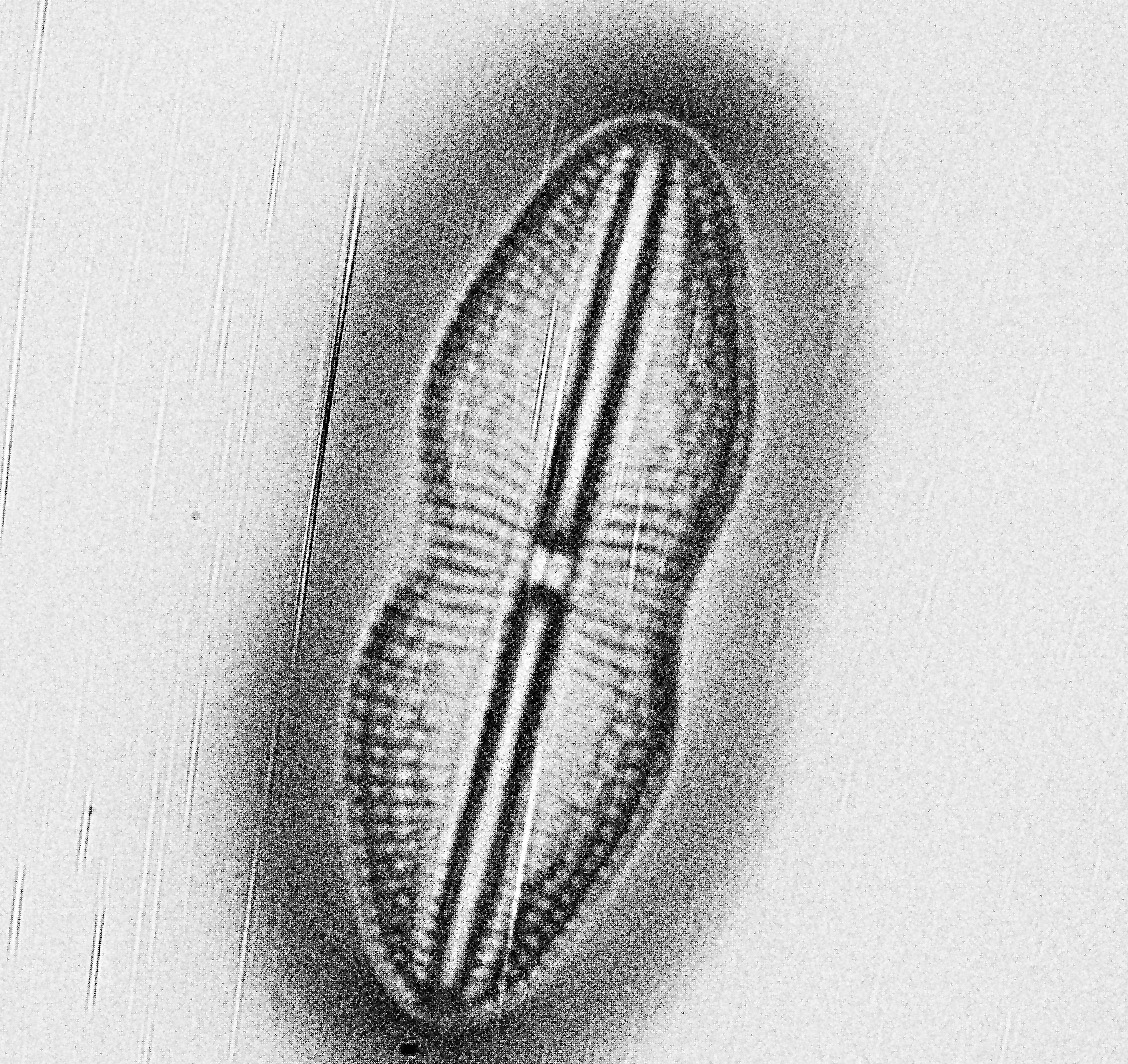
On saturday 15th October 2022, I attended the Quekex meeting of the Quekett Microscopical Club (of which I am a member). I had been asked to give a talk on my UV microscopy work on sunscreen and diatom imaging, and as it turned out I had also been awarded a Certificate of Technical Merit for one of my UV microscope images of a diatom (taken using 313nm light). A very successful and fun day and here’s a few pictures from it.
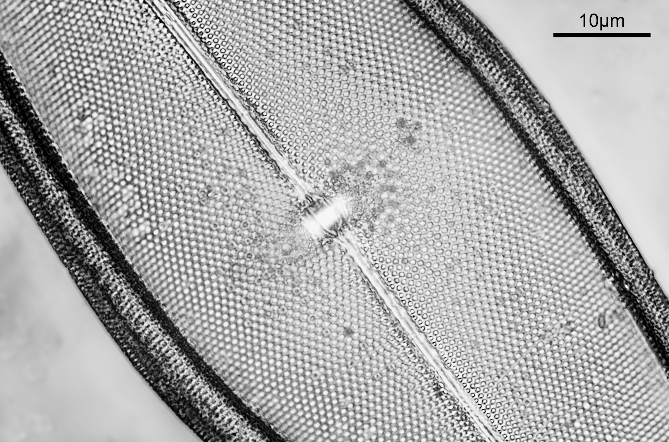
The title page from my talk to the club.My diatom image of a Pleurosigma Angulatum taking at 313nm on my UV microscope.The awards notice from the day (I’ve blurred other people for the sake of confidentiality).
If you’d like to know more about my microscopy or other work, I can be reached here.
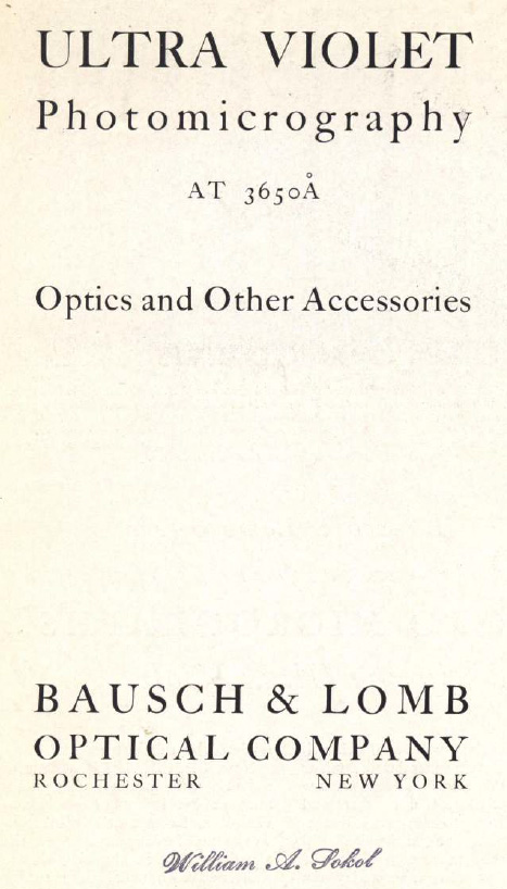
Given my ongoing research interest in UV microscopy, I am always looking out for information on the subject. A few days ago I found a brochure published by Bausch and Lomb which talked about objectives and other items they had made which were designed for use at 365nm. As I hadn’t heard about these before, and I haven’t found any more about these, I thought I would share it here.
The document was called “Ultra Violet Photomicrography at 3650Å Optics and Other Accessories”. Here’s the cover page.
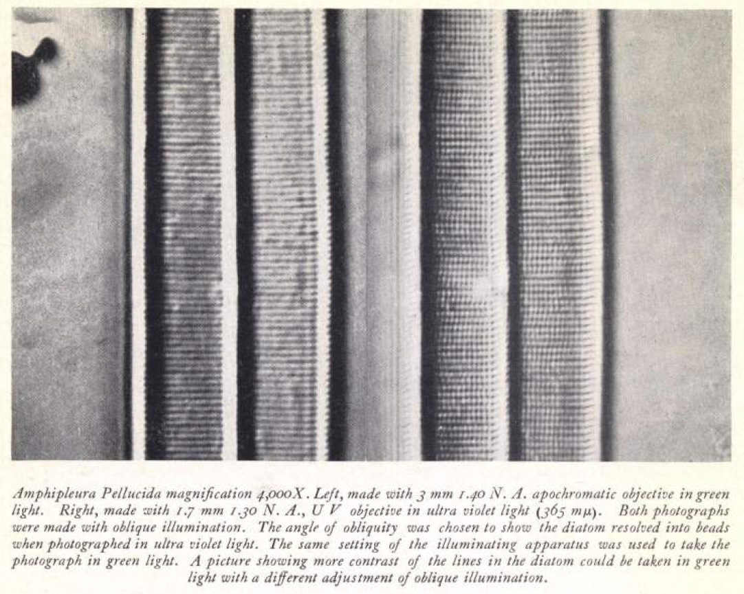
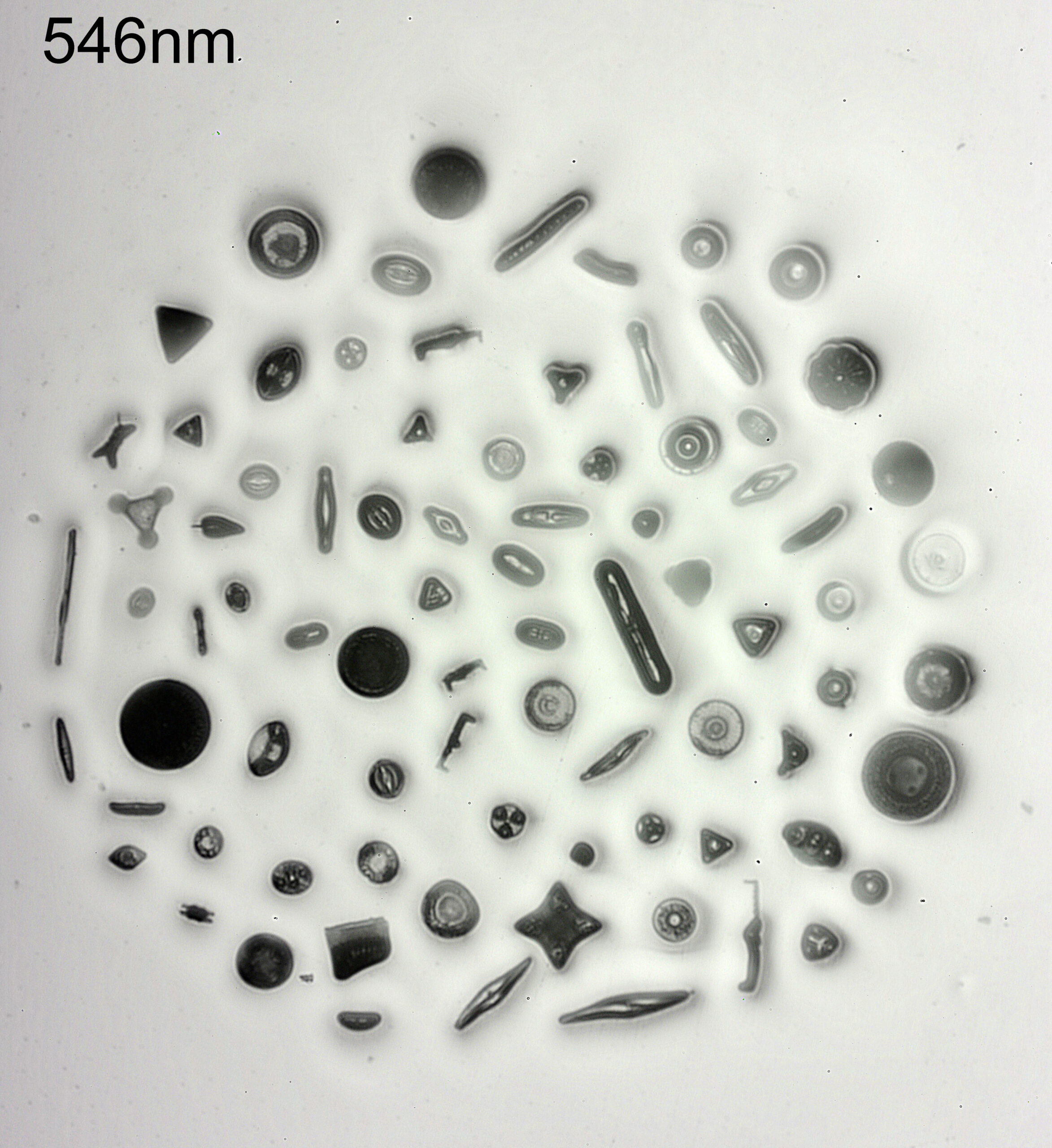
3650Å is 3650 Angstroms and is the same at 365nm. These are glass objectives and are corrected so the focus point at 365nm is the same as that at 546nm, so that they can be focused in visible light and then used for imaging at 365nm. This was done to improve resolution, as a ‘half way house’ imaging in the UV with glass optics but not going to the extremes of using quartz optics and imaging down below 300nm.
They give an example of the comparison between a 546nm image and a 356nm one of a Amphipleura pellucida diatom, which shows the improvement nicely.
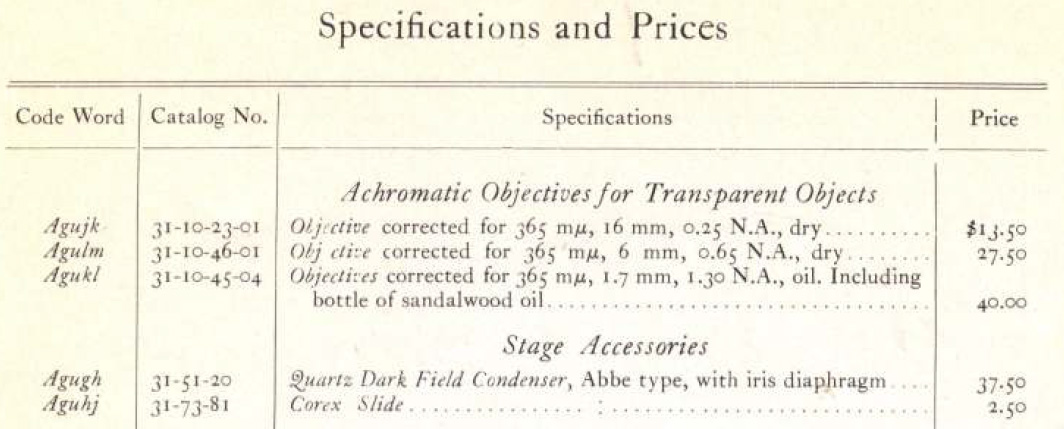
Here’s the information about the objectives.
Thing is, I had not heard of these before, nor have I ever seen any examples of them. If anyone has any, I’d love to see what they look like, and please feel to contact me here.
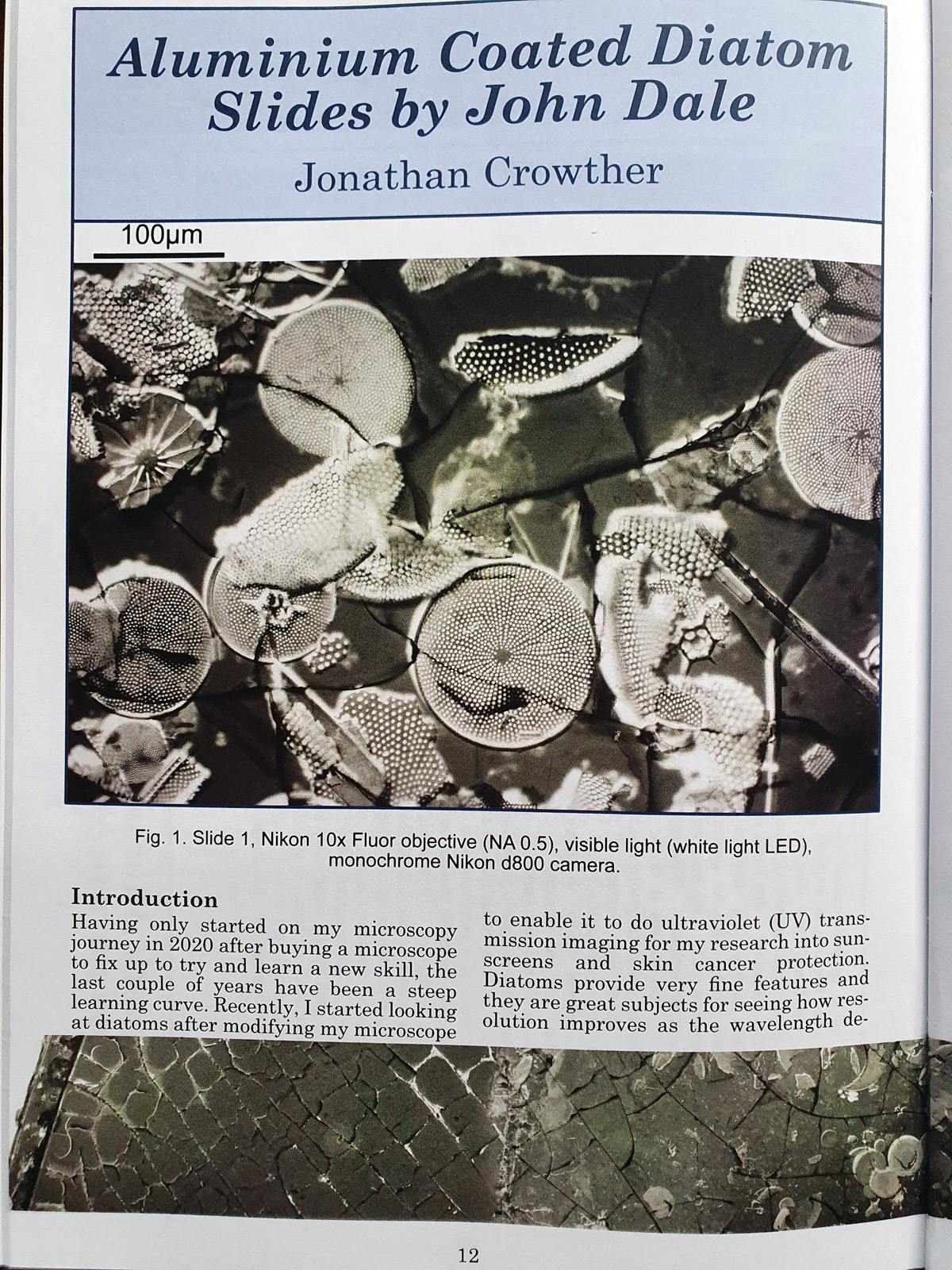
Always nice to see an article getting published. This time a piece in the Balsam Post, which is the newsletter of the Postal Microscopical Society. The article is on a set of aluminium coated diatom slides that the society has, and I looked at them with visible light and with 365nm UV using my UV microscope.
While I spend a lot of time working, it is nice to occasionally take a break and look at other samples using the equipment I’ve built. The quest for improved resolution in microscopy led me to looking and metal and metal oxide coatings for samples, and this resulted in me looking at the work of Horace Dall (who I have also written about before – here) and John Dale. The Postal Microscopical Society had a set of diatom slides by John Dale which had been coated in aluminium, so I requested those and offered to write a short article for their newsletter on what I found.
Organizations such as the Postal Microscopical Society and the Quekett Microscopical Club should not be overlooked when it comes to research. While not all the members will be actively involved in scientific research the collective knowledge of members is enormous, especially when it comes to historical work. I can do nothing but recommend anyone interested in microscopy look to join these groups. Giving something back by writing the occasional article is my way of saying thank you, and provides work which will hopefully be of help to others in the future.
As always, thanks for reading, and if you’d like to know more about my work, please feel free to contact me.
Short update today, as this is a work in progress. With UV microscopy, conventional glass lenses absorb the short wavelength UV, and become opaque. This means using quartz, fused silica, calcium fluoride, etc for lenses especially when going below 300nm. I have some commercially made UV objectives, but nothing with a low magnification – the lowest magnification I have is a 10x one (which equates to a 16mm focal length on my setup). Having a wider field of view is nicer for looking at big samples, but there is of course a trade off in resolution. This got me wondering if I could make my own objective using a simple fused silica single lens, which is the topic of this post.
To make it I went back to my old friends – Thorlabs – for the components. For those of you who don’t know, Thorlabs is an excellent optics supplier, a sort of Lego for optics geeks, and offer a huge range of components. I’ve written about them before here. For the initial attempt I decided to use a 40mm focal length, 25mm diameter, plano convex fused silica lens, as I had one already. This was mounted in a Thorlabs SM1 tube, and then a RMS to SM1 adapter so it could be screwed into a normal microscope objective port on the microscope. I also fitted another SM1 tube to act as a light baffle to help remove stray light. Here it is on the microscope, pointing at the sample.
Home made 40mm microscope objective pointing at the sample.
The sample is my fused silica diatom slide for UV work. The diatom arrangement is about 2mm across, and is far too big even for a 10x objective.
Here’s how it looks using visible light (546nm).
Diatom slide in visible light.
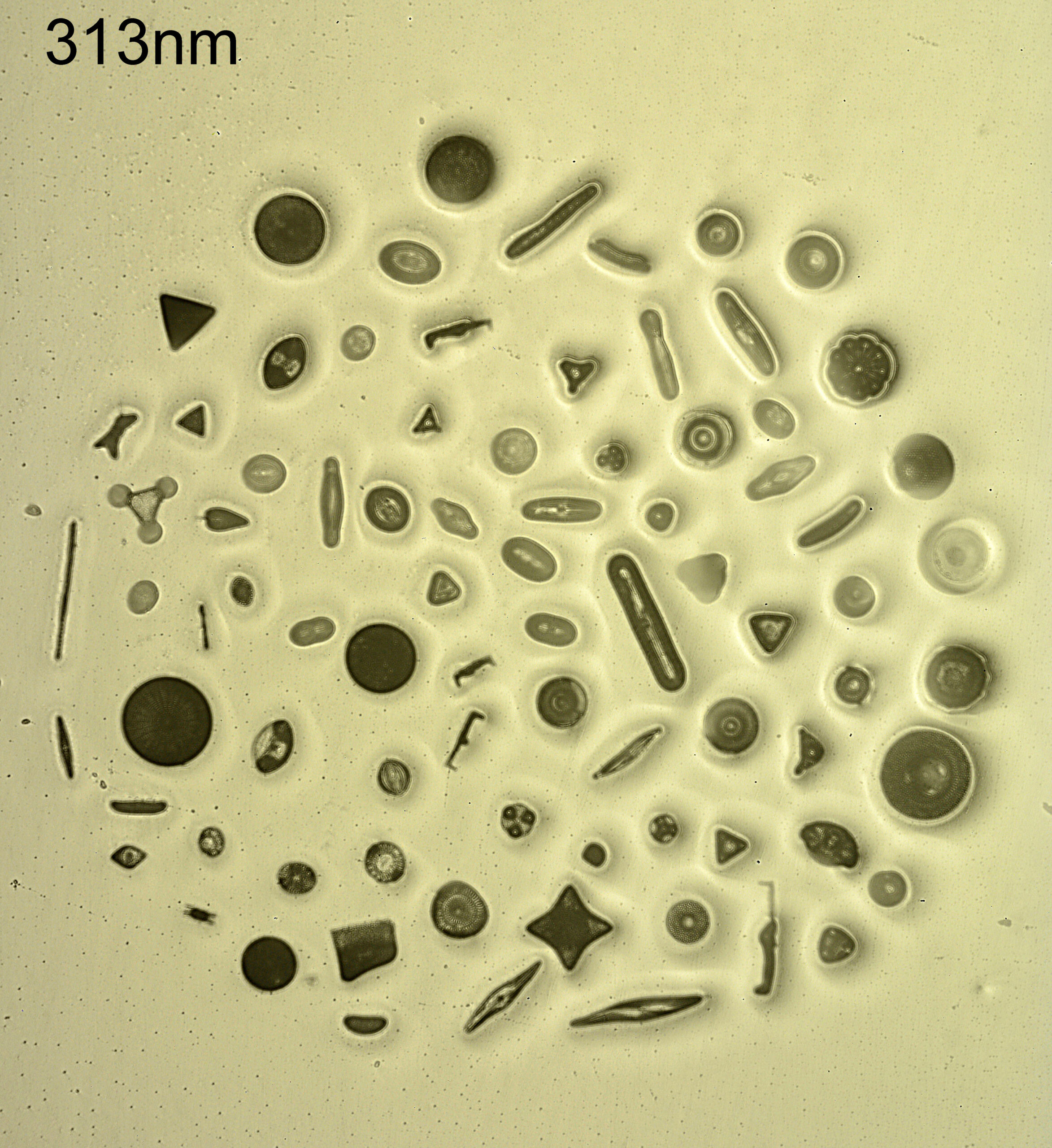
And now with 313nm light.
Diatom slide using 313nm light.
The good thing is it does image the whole of the arrangement, but they are very soft images. Not a huge surprise, this was a single 40mm focal length plano convex lens after all. This was more a proof of concept than anything else. The dirt in the mount it more obvious at 313nm. Again not a massive shock as the shorter wavelength light shows more dust and dirt. Some (but not all) of the diatoms look darker at 313nm than at 546nm, and this is what I have seen with my imaging. There is also a slight change in size of the field of view when changing wavelengths – 546nm and 313nm focus at different places with this lens, so the sample needs moving as the wavelength changes. This is easier to see if I flip between the two images (click on the image for this to work).
546nm and 313nm images combined.
Can I make my own objectives using stock components? Yes. Would I want to use a simple plano convex lens for my microscopy? No. Too soft and too low a contrast. I have got a couple of aspheric lenses on order from Thorlabs (one is fused silica the other in glass) to see how they work better – being aspheric I am hoping for a slightly sharper image from them.
As always, thanks for reading, and if you’d like to know more about my work, I can be reached here.
Quick update today – the latest edition of the Handbook of Cosmetic Science and Technology has been released. I have a chapter in it on the use of UV imaging for skin and cosmetics, and it is great to have work in such an influential skin research textbook.
Congrats to the editors, as this one has been in the work a while (it started pre Covid).
Combining multiple images together which are taken with different focus points is a valuable tool for microscopy, as it allows thicker subjects to be imaged and for it all to be in focus. This focus issue can be a big problem with microscopy as especially with high magnification and high Numerical Aperture (NA) objectives, the depth of field can be tiny, often well under a micron. The process of of combining images like this is called Stacking. There are various piece of software to do this including Zerene Stacker, and Helicon Focus, and I personally use Zerene Stacker. Today’s post isn’t a ‘how to’ with stacking, as I am no expert in it, but I wanted to share a diatom image which I recently did for which stacking we very helpful, and to show you the effects of using it.
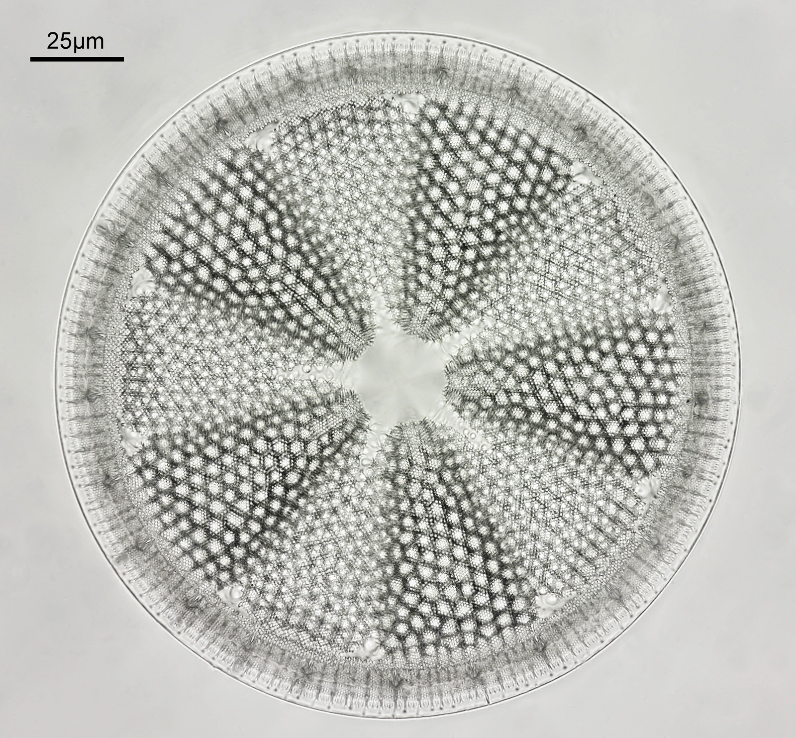
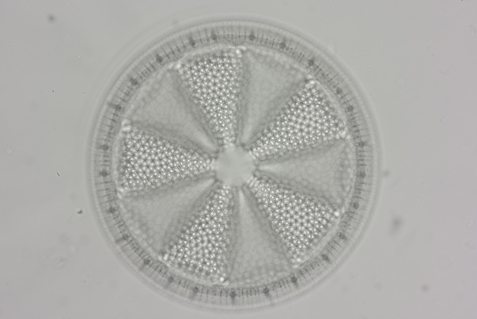
Firstly the final image, and then I say how it was done. This (I have been told by experts) is an Actinoptychus heliopelta diatom. It has been reduced in resolution for sharing here – the original was 5202×4823 pixels, and this copy is 1600×1483.
Stacked image of an Actinoptychus heliopelta diatom.
Also a crop from the original, and even this needed to be reduced in size to make it suitable for sharing.
Crop from the stacked image of an Actinoptychus heliopelta diatom.
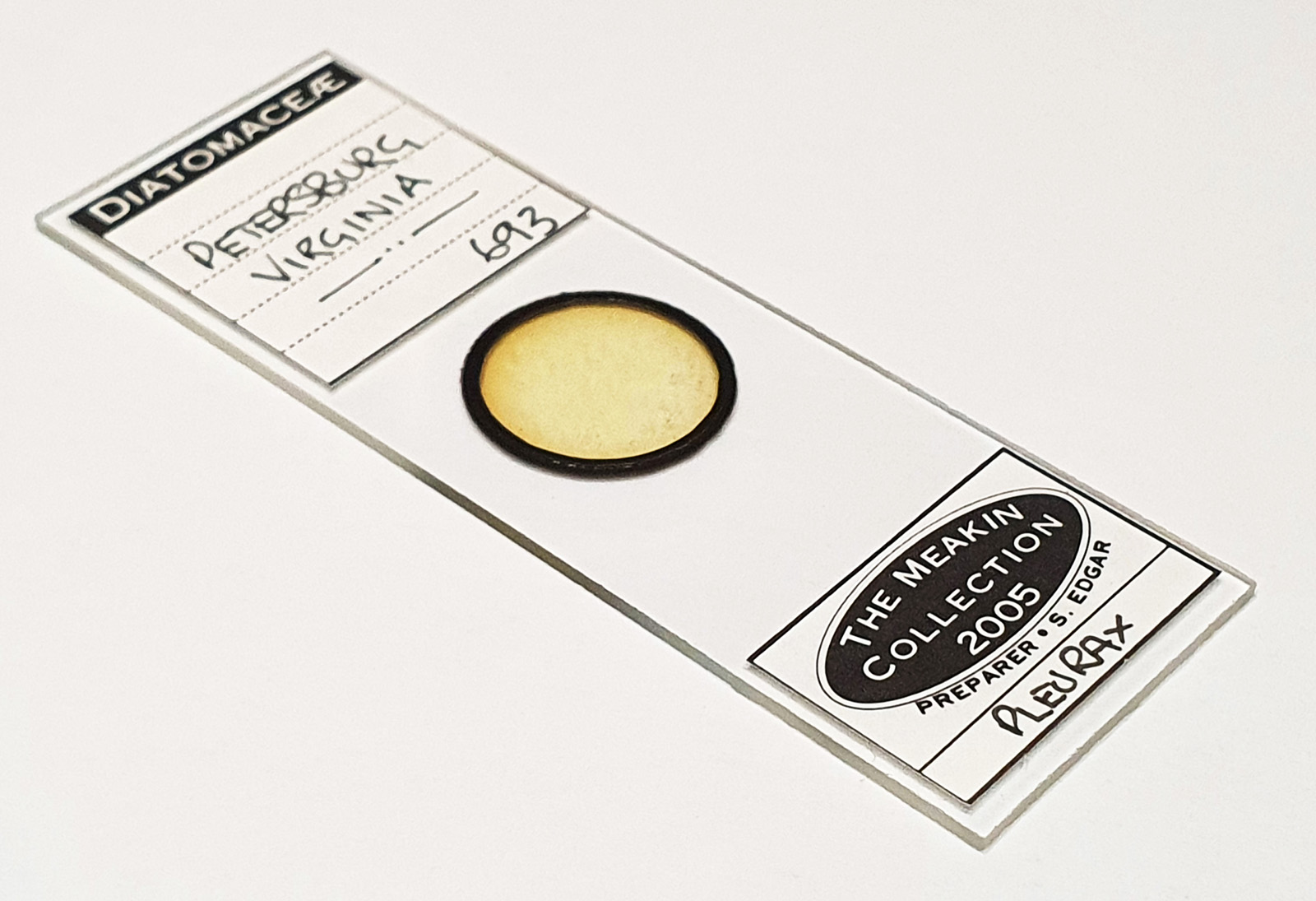
This was photographed using my modified Olympus BHB microscope which I built for UV microscopy of sunscreens. The camera was a monochrome converted Nikon d800. The objective was a 60x Olympus SPlan Apo NA 1.4 oil immersion. Condenser was an Olympus Aplanat Achromat set to oblique illumination. The light source was a white LED one I made. The image was made from a stack of 18 individual photos at different focus points, combined in Zerene Stacker using what they call the Dmap process. I’ve also cleaned up the image, sharpened it, and tweaked the curves. As you can see though the majority of the diatom is in focus. The diatom was on a slide from the 2005 Meakin Collection (Petersburg, Virginia) which I got as part of a recent purchase.
Slide used for imaging.
So, why bother stacking? It comes back to the issue of sample thickness, and the depth of field that is possible with the objective. By taking multiple images, moving the stage vertically so that different parts of the image are in focus, during the stacking process the software then takes the ‘in-focus’ parts of each image and combines them together to produce the final image. To help visualize that, here are three images from the original stack, taken at different stage positions. These have not been cropped, but have been reduced in size for sharing. They have also not been cleaned up, as I did this at the end.
Diatom image 1.Diatom image 2.Diatom image 3.
As you can see, the three images each have different parts of the diatom in focus, and one single image would not have captured the whole of the diatom AND got it in focus.
The software itself is straightforward to use, but it takes a little bit of experimenting the get the best settings that it uses for processing. This will likely depend on your setup, and to some extent personal taste when it comes to how you like your images. Give it go, and open up a whole new way of looking at your microscope images. To be clear the technique is not suitable for all subjects – if there is movement between each image then that can be a problem. This is why I do not use this for sunscreen emulsion imaging, as there is often some small degree of movement of the droplets.
As always, thanks for reading, and if you’d like to know more, please contact me here.
A long time ago I did a PhD in surface chemistry at the University of Durham. My professor (Prof Jas Pal Badyal), is still there and still doing great research. Some of my equipment is still in the lab, and I was lucky enough to visit there earlier this year and see some of the work the team are doing. During my PhD, some experiments were done which produced results which I never fully answered. However with my new interest in microscopy it has helped me look at my PhD again with different eyes, and cast light on some of my observations from over 25 years ago. Today I’d like to share these with you.
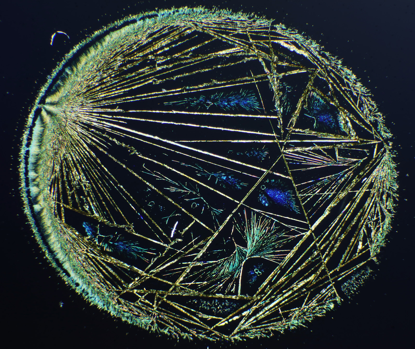
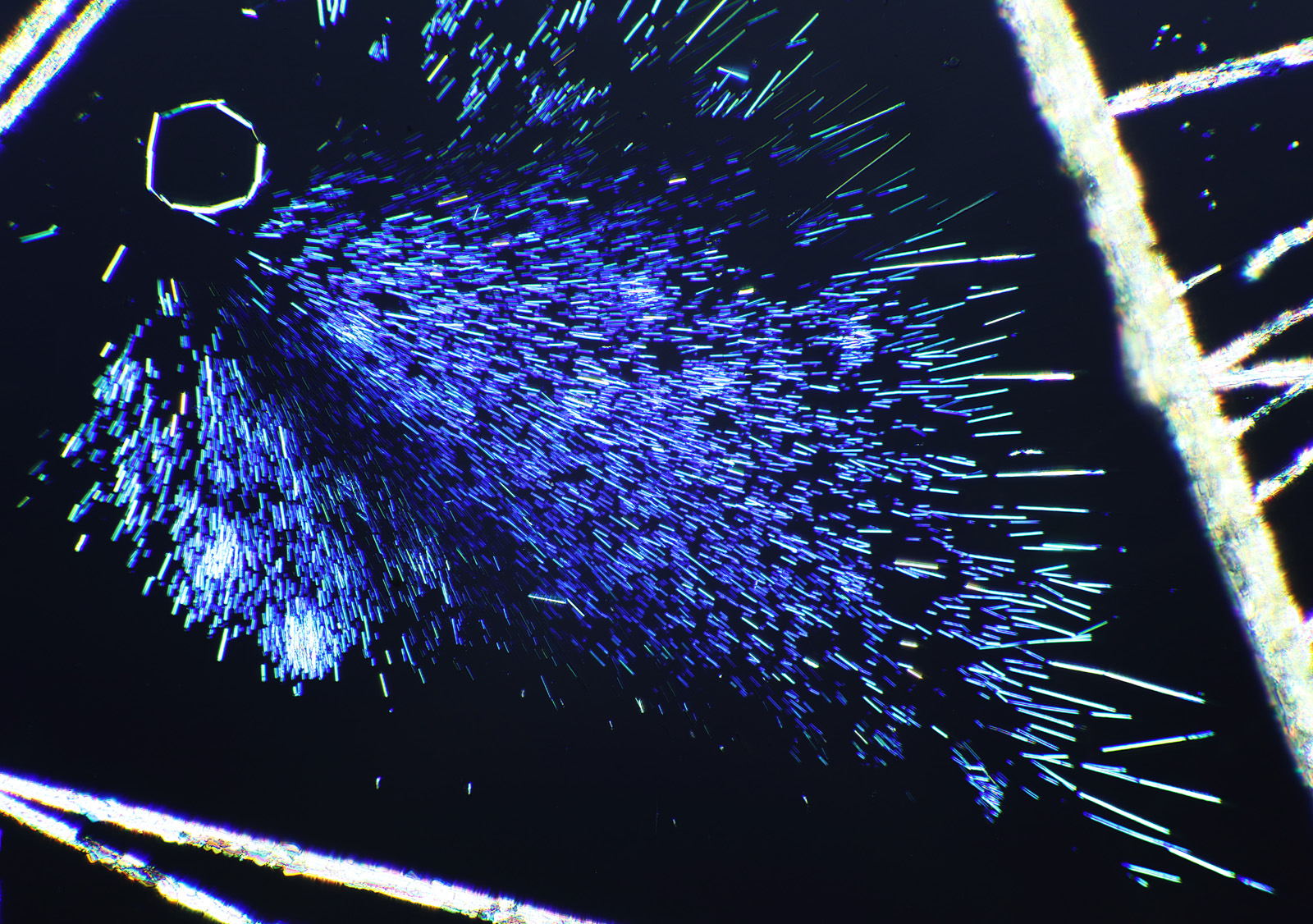
The first was purely a few nice images from a microscope slide I bought. During my PhD I worked with precious metal compounds. I’d dissolve them up in different solvents, spin coat them on to different substrates and then hit them with a cold gas plasma to reduce them down to metal layers. The goal of this was to find new ways to make catalysts on temperature sensitive substrates. At the time, I’d often get nice complex crystal structures and a few of these even made it into my PhD as rather poor quality photos. The microscope slide I got recently was of potassium platinum cyanide (a platinum compound) on glass. Under crossed polarized light, which is often used for the imaging of crystals, this is what it looks like.
Cross polarized image of potassium platinum cyanide crystals. Circle is approx 6mm across.
The image above was taken using an 1x Olympus SPlan FL1 objective, on my modified Olympus BHB microscope. The whole circle is about 6mm across. I removed the condenser and just used the field lens to cast light onto the sample given its size. Very often I’d get complex dendritic structures like this with silver and palladium compounds, and I struggled to photograph them with what I had to hand at the time.
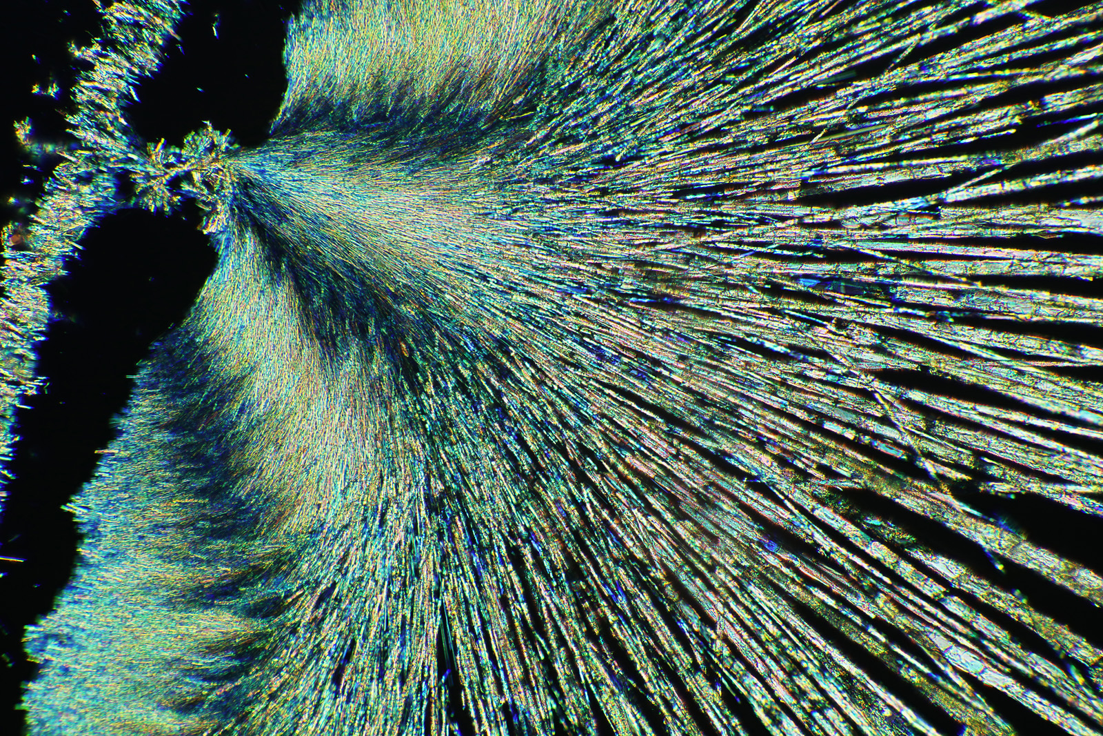
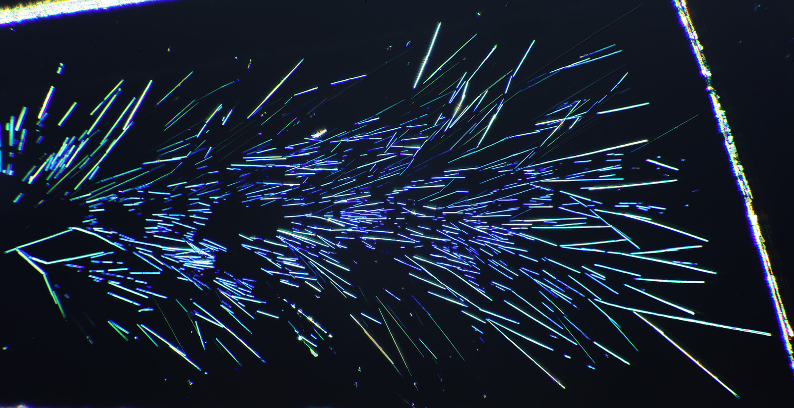
Here’s some more images from this slide as it is so beautiful and complex. These were taken with a higher magnification objective (a Nikon 10x NA 0.5 Fluor). If only I’d had this microscope back in my PhD….
Cross polarized image of potassium platinum cyanide crystals with 10x Nikon Fluor objective.Cross polarized image of potassium platinum cyanide crystals with 10x Nikon Fluor objective.Cross polarized image of potassium platinum cyanide crystals with 10x Nikon Fluor objective.Cross polarized image of potassium platinum cyanide crystals with 10x Nikon Fluor objective.
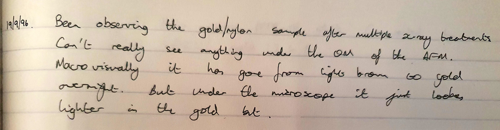
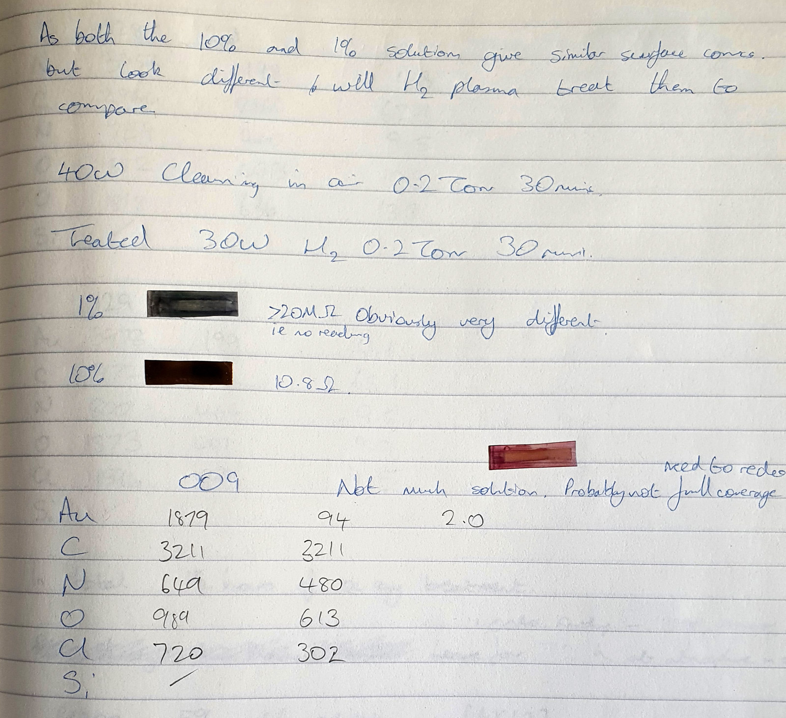
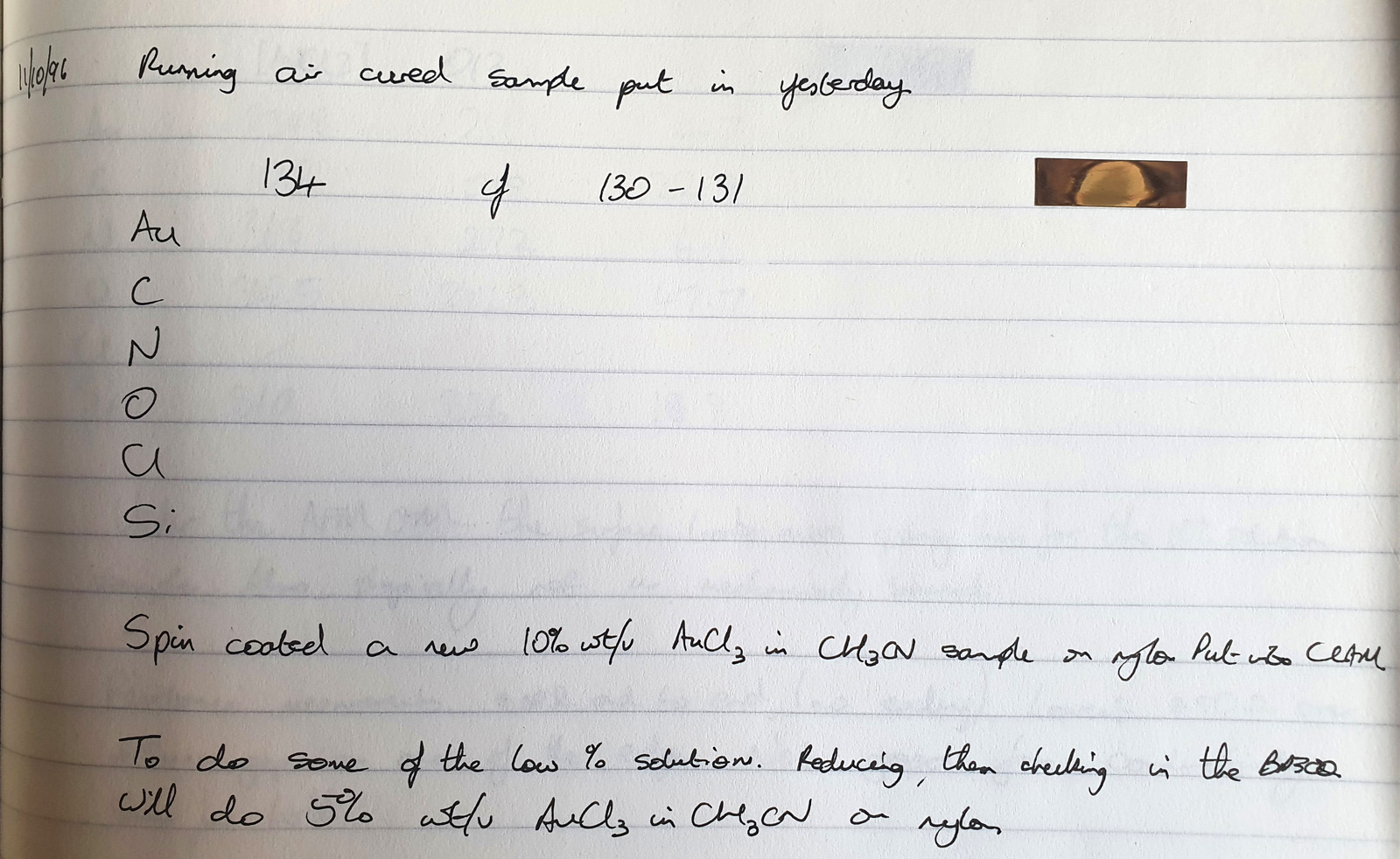
The second thing is a bit more of a technical one, and the purchase of a book gave me some answers I could have done with when I was back in the lab. This came about because of a chance observation one day. I used to deal with gold chloride (AuCl3) solutions. These were spin coated on to Nylon, and the result was the Nylon would slightly dissolve, and the gold salt and Nylon would mix together to form a thin layer. Normally I would then treat this with a hydrogen plasma to make a gold metal layer. To analyse the samples I used a range of different techniques, one of which was X-ray Photoelectron Spectroscopy (XPS) which involves using X-rays to irradiate a sample, kicking out electrons which are then collected and analysed. The energy of the electrons tells you about which elements are present. I noticed that with some of my gold chloride samples, if I analysed them before treating them with the hydrogen plasma, they would come out of the device looking different where the X-rays had hit the sample. They would be a different colour, often red or brown. Sometimes this sample would then change over the next day or so and become more ‘gold’ looking. Essentially, the X-rays were doing something to the sample. Here’s some of my original notes from my lab books from 1996 (and yes I still have my PhD lab books, and no my hand writing has not improved over the years). The little ‘letter box’ shaped things in the text are actually the coated Nylon samples from the experiment – I stuck them in the lab book where possible.
In the second image above, one of the samples looks to be transparent red, and this gives you an idea of what they looked like (this one never changed over time). When I originally did the work I suspected this effect was due to the X-rays breaking down the gold chloride molecule and forming nano gold clusters or colloids suspended in the Nylon polymer matrix. Depending on the precise nature of the X-ray treatment with some of these samples the gold clusters then migrated over time to form larger structures and eventually more coherent gold films. However this was a distraction from the actual work, as my main focus was plasma treatment, and I was never able to prove what was going on.
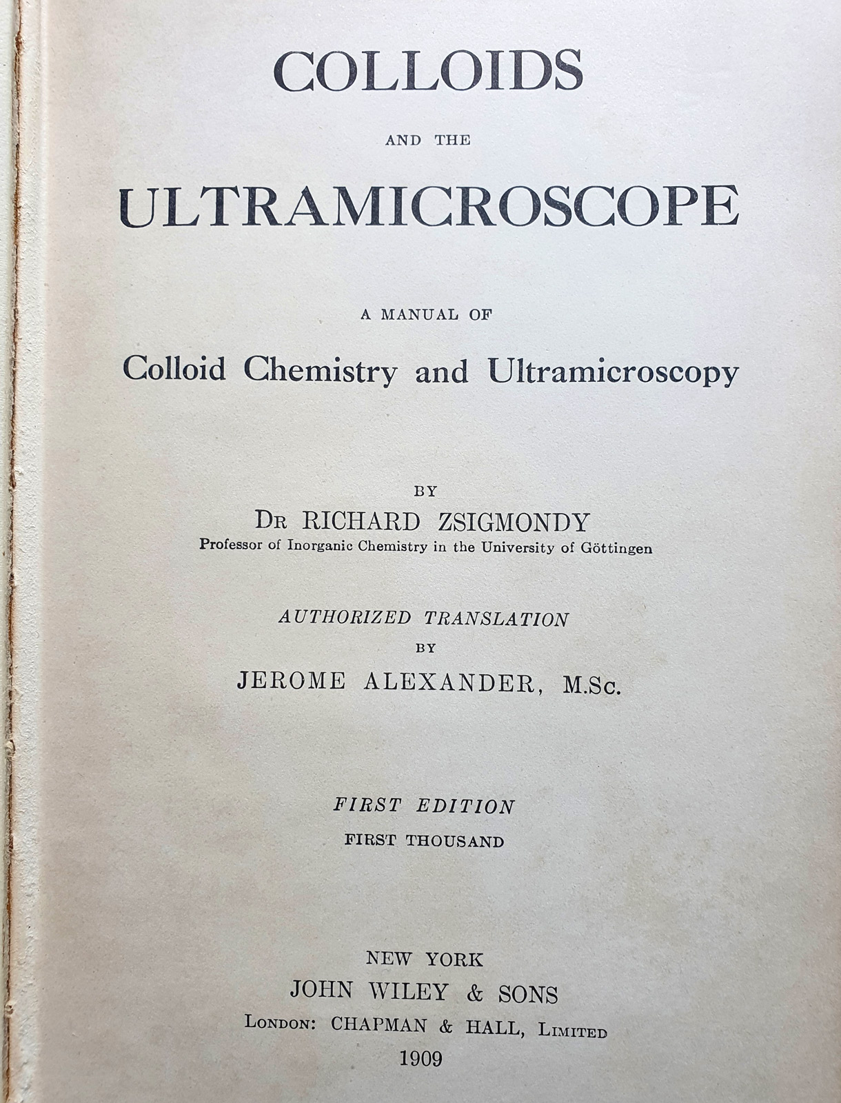
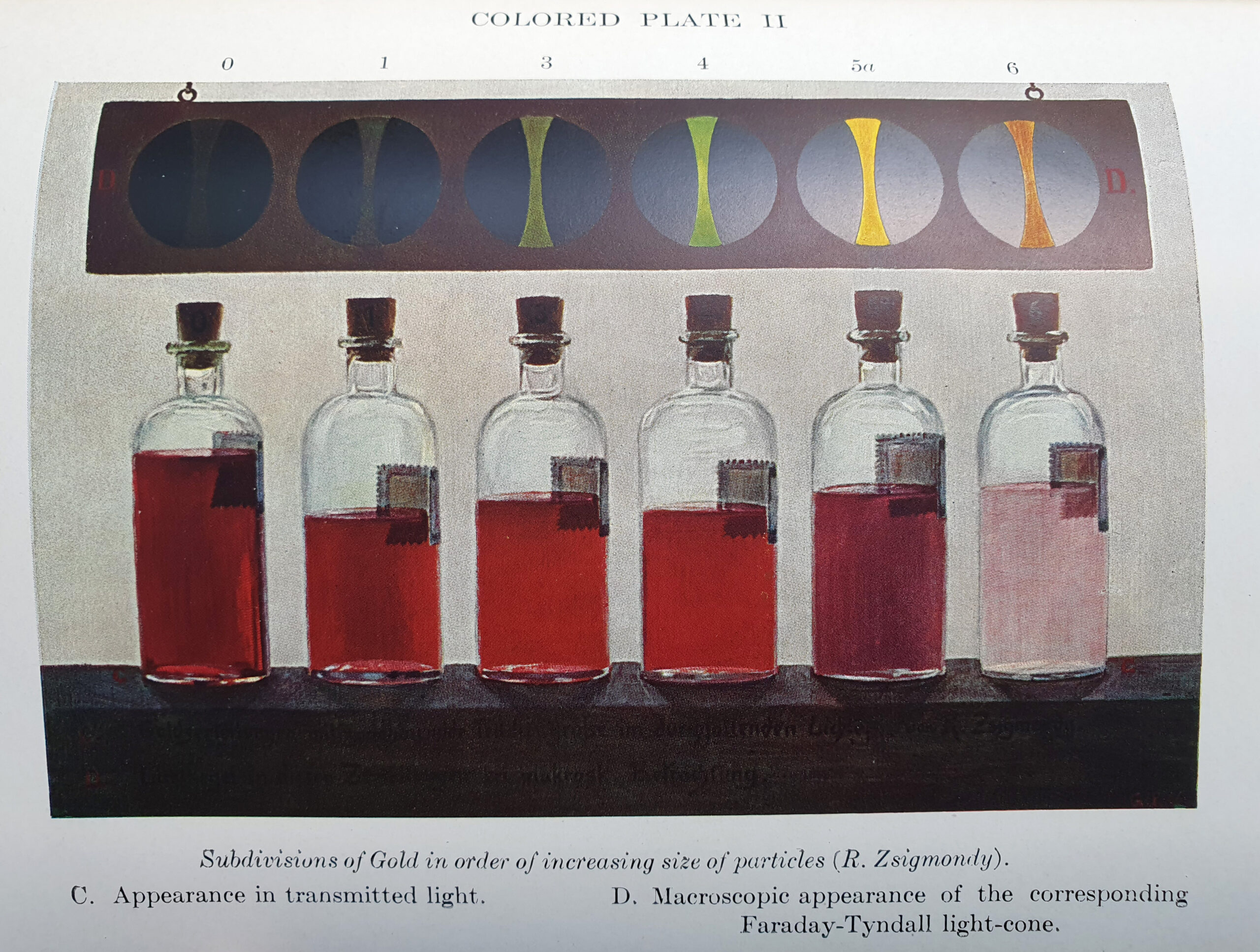
A few months back, I came across a book called “Colloids and the Ultramicroscope” by Zsigmondy, and translated by Alexander in 1909. This was for sale in the US, and being a bit of a nerd I bought it as ultramicroscopy was a technique I was interested in reading about as it was an approach to produce very high resolution images. Here’s the book.
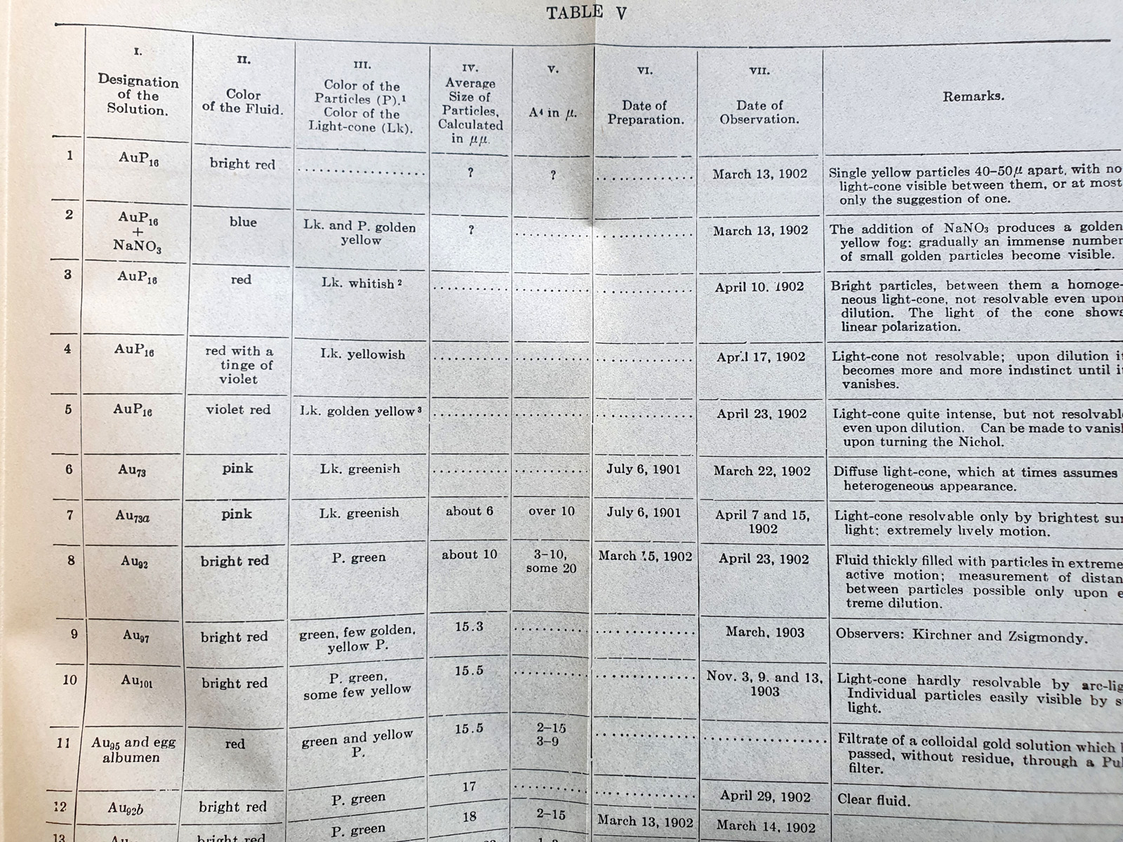
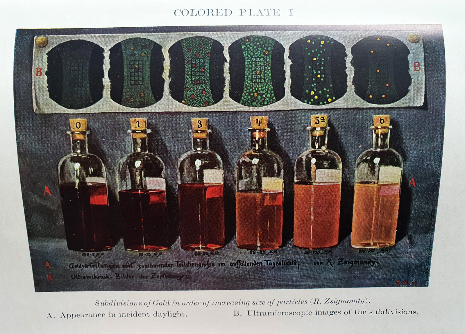
It turned out that he had used this technique to look at gold colloids, and amazingly the book had some tables and colour plates of gold colloid solutions with different sized particles.
It does indeed look like small gold colloids have that distinct red colour which I observed – the smaller the particle the more intense the red.
Very often as scientists our experiments throw up questions which we cannot answer at the time. Unfortunately, in today’s deadline driven world, these are often seen as problems – things which slow us down and distract from the desired goal. But the key driver for a scientist is exploring and hopefully explaining the unknown. Sometimes this happens quickly, but as in this case it can take years, and inspiration often comes from unexpected sources.
As always, thank you for reading, and if you’d like to know more about the work I do, I can be reached here.
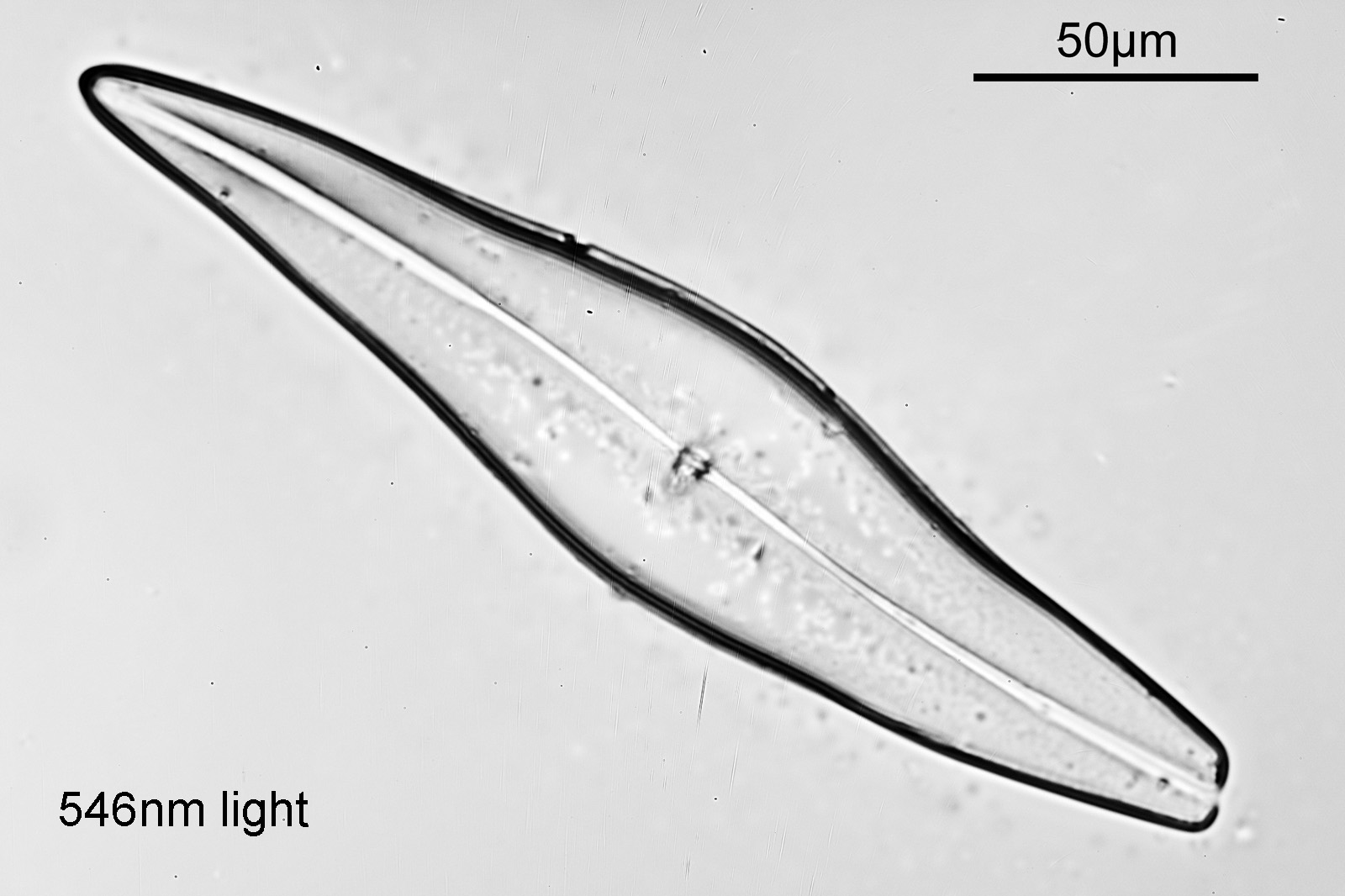
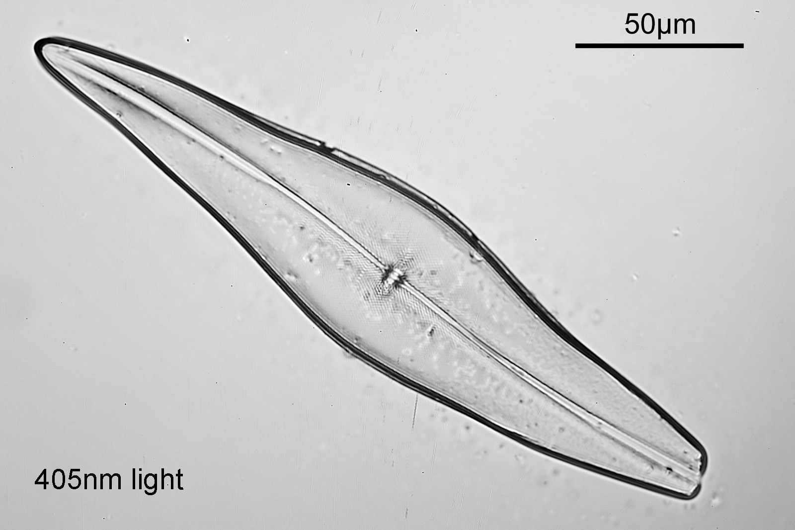
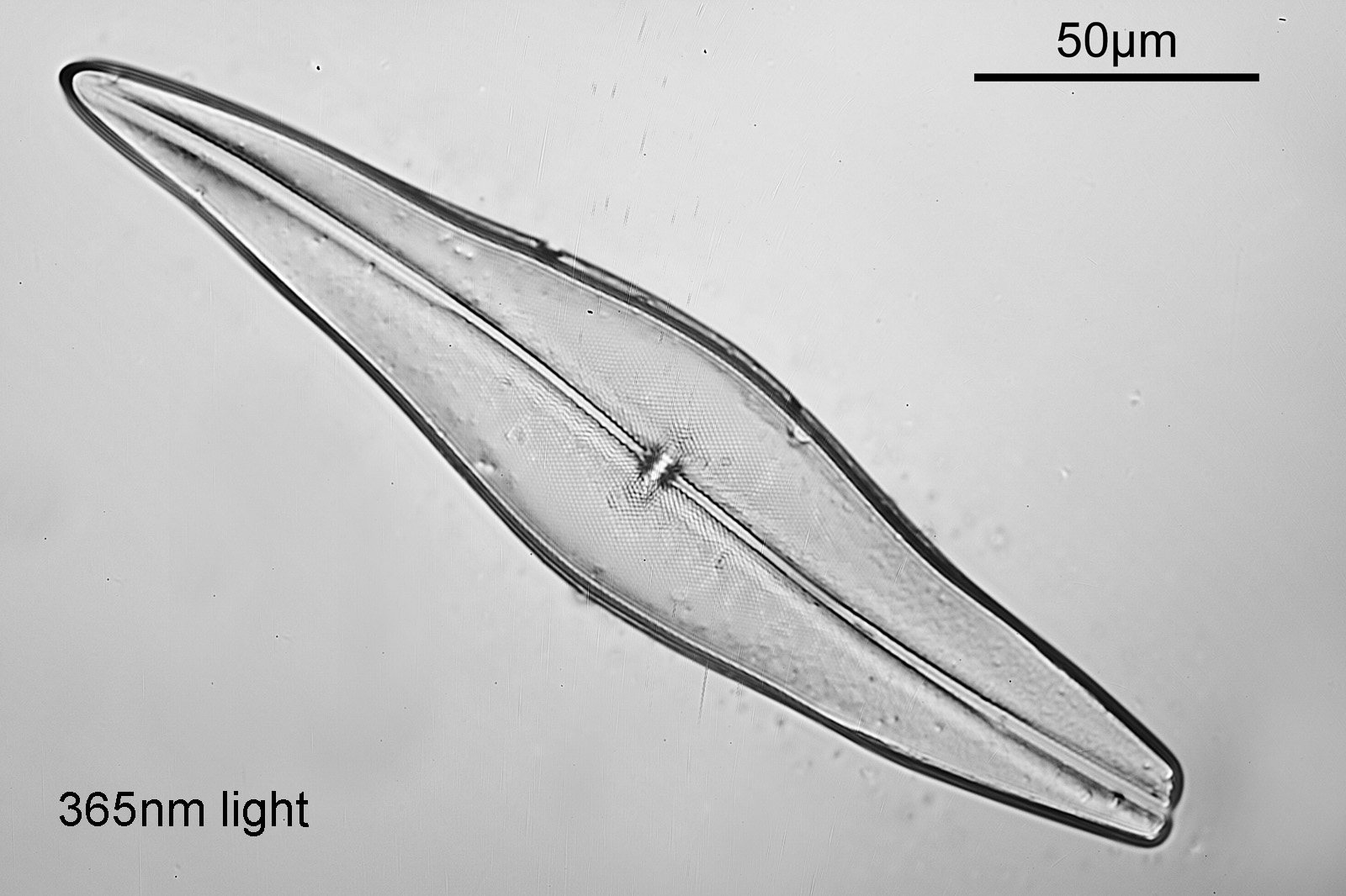
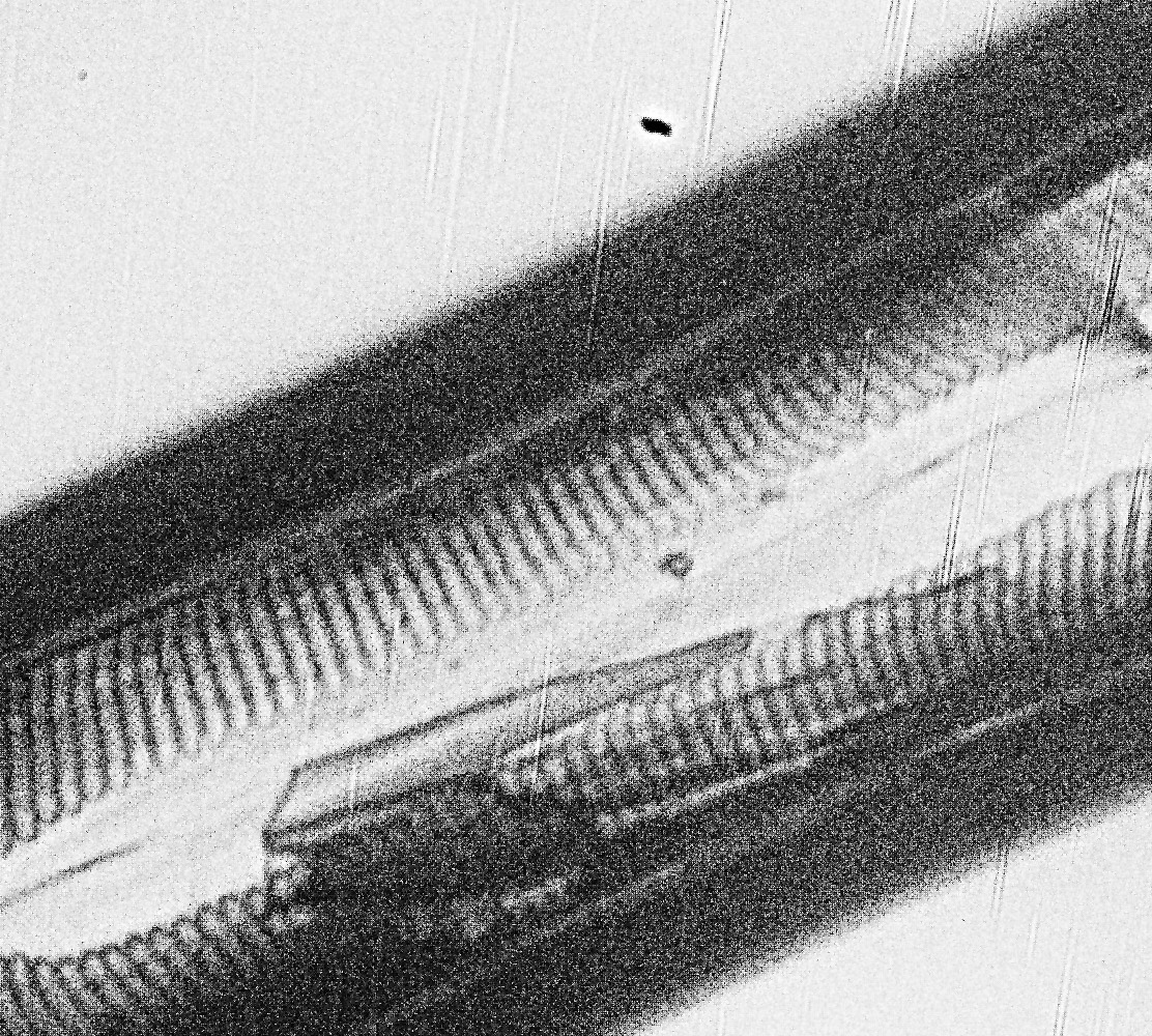
One of the original reasons for moving to UV for microscopy was that of improved resolution – the shorter the wavelength, the better the resolution for a given numerical aperture. I’ve discussed this effect before (for example see here) but in my earlier work, I was limited to 313nm as my lower limit for wavelength. With my new work using 254nm I thought I would do a little test with one of the diatoms on my test slide and see how it looked as the wavelength changed. Today I am sharing those results.
For this test I used a 32x Zeiss Ultrafluar NA 0.4 objective. For now this is highest magnification objective I can use at 254nm. This was used without any glycerin immersion (it’s labelled as being for glycerine immersion, but can also be used without). Camera is a monochrome converted Nikon d850 from MaxMax. Light source for 546nm to 313nm was a mercury xenon lamp, and for 254nm a low pressure mercury lamp. Images are the full size, but reduced in resolution for sharing from the originals (which were nearly 50Mp). All images saved as RAW files and processed in Darktable, and all have had the same degree of sharpening. Simple brightfield images. Wavelength of light used shown in the bottom left of the images.
I’ll show them in the order going from long wavelength to short.
Even with the small images used here, the improvement in resolution as the wavelength is reduced is quite obvious. The diatom (a Pleurosigma angulatum) has features on it which are not visible when viewed with 546nm light with this objective – the dots or punctae. They are too small to be resolved with the NA 0.4 objective at 546nm. At 405nm they start to become faintly visible. They become more obvious at 365nm and even more so at 313nm. At 254nm, they might even be more apparent, but the nature of the image makes it harder to be certain. I also had to up the ISO for the 254nm image from 200 to 400, as the camera has virtually no sensitivity that far down. Even doing this it needed a 15 minute exposure at 254nm vs a 4 second one at 313nm. The silica based structure of the diatom also becomes darker at the shorter wavelengths, as it absorbs more of the light. This helps with contrast and is in itself a good reason for me to keep pursuing this technique.
There is however a big and obvious issue with the 254nm image – the heavy ring artifacts. I saw this to a lesser extent with the 10x objective, and I am not 100% certain as to the reason for it. One possibility is something called window etaloning, where incoming light is reflected from the front of the camera sensor, before being reflected back again from the underside of the sensor coverglass. It bounces back and forth and causes these light and dark bands (there’s more info about it here). This could be more of an obvious issue at 254nm as the reflectance of silicon used for the sensor is quite high down there (higher than the longer wavelengths). However with the 254nm light I do not have a diffuser on there, unlike the the light used for the other wavelengths, and I cannot rule that out as a possible contributing factor.
254nm UVC microscopy continues to present some very strong technical challenges, however the improved contrast and resolution for diatom imaging is obvious, and it is something I shall continue to work on as and when I get the chance. As always, thanks for reading, and if you’d like to know more about this or any other aspect of my work, I can be reached here.
A couple of weeks ago I posted my first microscope image captured at 254nm using my UV modified Olympus BHB microscope (see here). While it showed the potential of the technique, it highlighted a number of issues which still needed addressing – especially the lighting (making it stronger and more collimated) and the filtration of the light to remove unwanted wavelengths. This is a bit of an update on progress since then, mainly with regards to the lighting, but also a mention of a slight change to filtration of the light which is imaged.
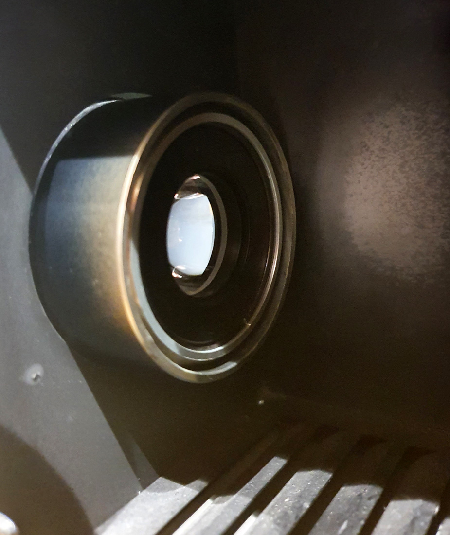
The main issue with the lighting was that it is a light bulb, emitting light in all directions. This is very wasteful and I need a focused, collimated light source, wasting as little as possible. In the original lamp housing there was a glass condenser lens which could be moved in an out to provide some focusing. Glass is fine for visible light, and even maybe for 365nm depending on thickness and coatings, but is no good at all for 254nm as it would just absorb everythin. This means needing to use lenses made from UV fused silica, quartz or materials such as calcium fluoride. As you can imagine the availability of lenses in these materials is much more restrictive (and the cost much higher) when compared with glass. As a result I tend to have to choose off the shelf components, which are ‘close’ to the parameters of the original pieces, rather than ones which are exactly the same. The original glass condenser lens was about 42mm diameter, while off the shelf components were available in 25mm or 50mm diameter. I went with a 25mm UV fused silica aspheric condenser lens with a 20mm focal length from Thorlabs (see here). This was mounted in one of their SM1 tubes, which in turn was screwed in to an SM1 to M42 adapter. The M42 adapter was just the right diameter to fit into the lamp housing where the original lens did, and be held in with the original retaining clip. Bonus. This is where I give a ‘shout out’ to Thorlabs. As I’ve mentioned before, they are great to deal with and have an amazing range of optical equipment. Plus they send out Labsnacks with their orders….. This is how it looked once put together (you can see the lens in the middle of the adapter).
Thorlabs 20mm focal length UV fused silica aspheric condenser lens in the lamp housing
When I measured the intensity of the light at 10cm from the bulb with the lens in place I got about 6x more light than without the lens, which is a great improvement and will help with the imaging.
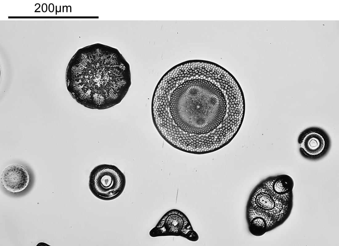
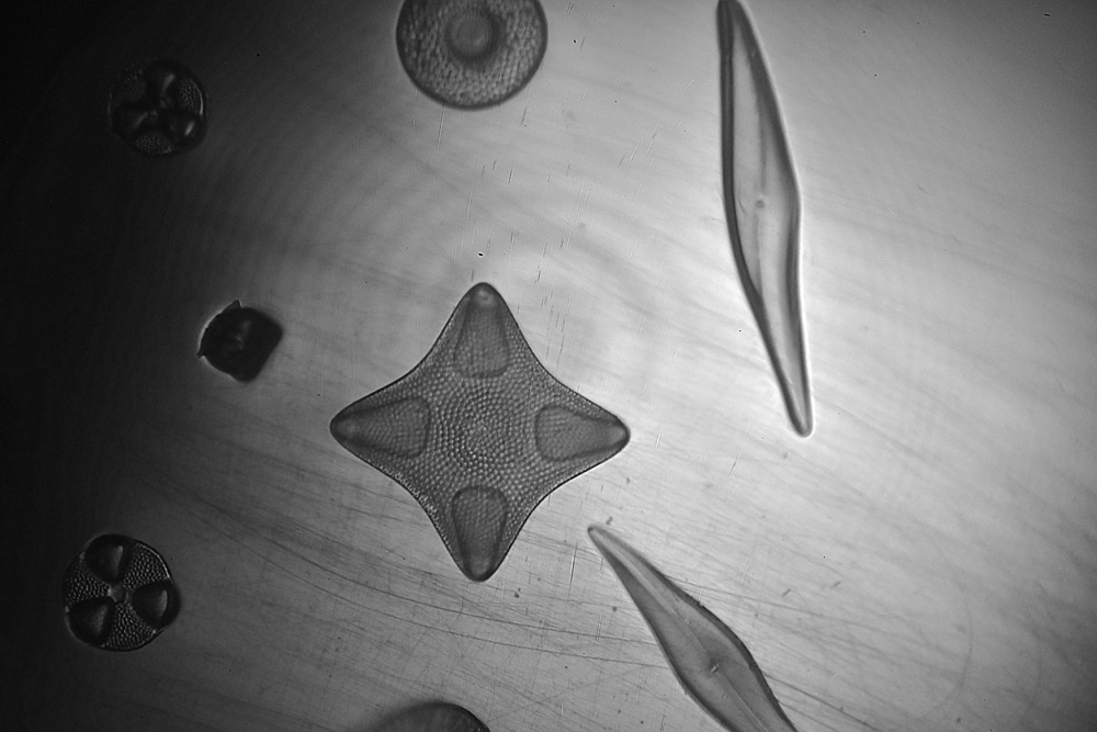
What do the images look like now? In a moment I’ll some examples from the fused silica/quartz diatom test slide, taken using a 10x Zeiss Ultrafluar NA 0.2 objective lens. The full sized images have been reduced is resolution for sharing here.
First though, a visible light (white LED) image of part of the slide with the same objective.
Visible light (white LED) image of the diatom test slide
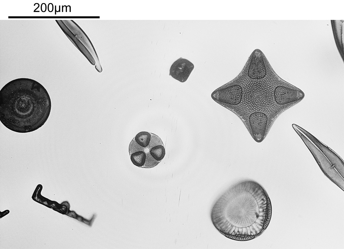
The same region of the slide now imaged at 254nm.
254nm light image of the diatom test slide
The modified lighting has helped a lot with getting an even light distribution across the image. It’s interesting that some of the diatoms seem to be absorbing quite a lot of light at 254nm while others do not (this is in keeping with some of the literature I’ve read on the subject). I am getting some rings in the lighting, which I think is down to the very reflective surface of the filters. I need to do a bit more work and see if that can be rectified.
A couple of other images of the slide at 254nm.
Diatom slide at 254nmDiatom slide at 254nm
Finally, some crops from the image above, shown at the original pixel resolution.
Cropped image of the diatom slide at 254nmCropped image of the diatom slide at 254nm
Doing some math on the images, in the original un-cropped images, there were 11 pixels per micron. If you look at basic Abbe resolution calculation for this objective (λ / 2xNA) you’d get a theoretical resolution of 635nm for this objective at 254nm. Some of the features in the cropped images above are of the order of 7 or 8 pixels across or about 750nm, so similar to the theoretical resolution limit predicted by Abbe. Now this is a bit of a simplification, as I really should take into account the NA of the condenser underneath the stage (which would push the theoretical resolution to smaller features) and the MTF function of the camera and lens (which would push it back towards bigger features), but I’ve not had enough coffee for that yet.
The images above are a bit noisy. I had to use 30s exposure at ISO1000 as the camera sensitivity this far into the UV is low. I am hoping longer exposures at lower ISO will help with that in future, or perhaps I’ll try stacking multiple exposures if I figure out how to do that.
Before I wrap up this post, I want to briefly mention filtration of the light before it reaches the camera. In my original post I was using a UVC bandpass filter which came from a forensics camera I bought a few years back. While this had good blocking of longer wavelengths, it had relatively low UVC transmission (about 20%). I decided to get another UVC bandpass filter and stack the two together, the aim being to improve blocking of unwanted wavelengths. The new filter is a Semrock 260/16 Brightline one which I bought from Laser2000 here in the UK (another company I’ve had good experience with in the past). This isolates the 250-270nm region very well, and blocks the rest of the UV and visible light. However it does not block the IR. So far, the initial tests with the two stacked together look good, and I’ll talk more about this filter in a future post as the whole area of filtering light for imaging at 254nm warrants a bit more of a discussion than there is time to do here.
As always, thanks for reading, and if you’d like to know more about this or any other aspect of my work, you can reach me here.
I’ll leave you with my standard warning for anyone considering working with UVC – don’t do it unless you know what you are doing and are using the right safety gear and clothing. UVC can be extremely damaging to eyes and skin, and it isn’t worth taking the risk unless you have the correct safety procedures in place.
Bit of a short update today, but there will be more to come on this after I have done some more work on it. Last year I reported being able to photograph in the UVC at 254nm with some of my modified cameras (for example see here). When I was building my UV microscope I wanted to make sure that it would be usable that far into the UV, even though the logistics of actually making it happen would be challenging. Recently I got hold of a small UVC light source which could make this more feasible, and I wanted to share some initial results from it.
Firstly though, a word of warning. UVC at 254nm can be extremely damaging to the eyes and skin. Do not attempt any work like this without the proper safety equipment and knowledge of how to use it. You have been warned……
The camera I used was my MaxMax converted monochrome Nikon d850 which is one I’ve used previously for UVC imaging. The light source was a 3W UVC lamp (a bit more on that later) mounted in a spare Olympus lamp housing. The slide was the diatom slide that I had made using fused silica/quartz instead of glass, and the one I’ve been using for my imaging work at 313nm and 365nm. I used a 10x Zeiss Ultrafluar objective. The light was basically just put in the empty lamp housing and moved around until I could get an image with it. And this is a first image at 254nm….
Diatom slide image captured using 254nm light
As images go this perhaps is not as impressive as some others. But the key thing to remember here is that this was done using 254nm and captured on a (modified) high street camera. There are some issues, and these will need to be overcome with future work. The image isn’t pure UVC – the camera has so little sensitivity down there that there is some contamination from other wavelengths. Based on some tests done at the same time, about 90% of this image is UVC related and the rest isn’t. I have another filter on order which will probably be stacked with the one currently being used. Better blocking of unwanted wavelengths is needed. The light source was not focused at all, and a lot was lost. I’ll be building a UVC focusing system for the lamp over the next couple of months. Image acquisition times are long, very long. Part of this is due to lack of focusing on the lamp, but part is just down to lack of camera sensitivity. It’s a pain, as I cannot use live view to optimise the focus, and everything has to be done slowly. This image above was not the best focus, but was a proof of concept one. No simple answer to this, other than hopefully the focusing system that needs to be built.
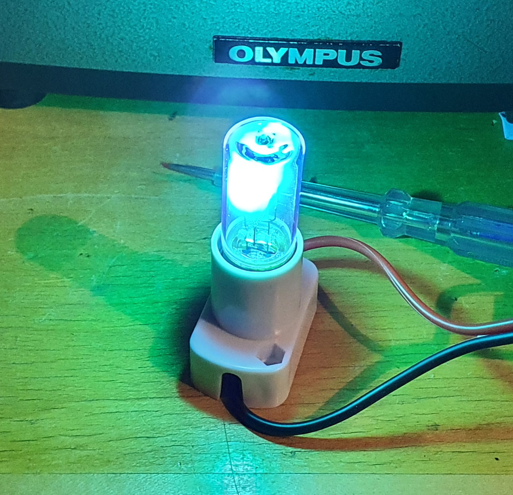
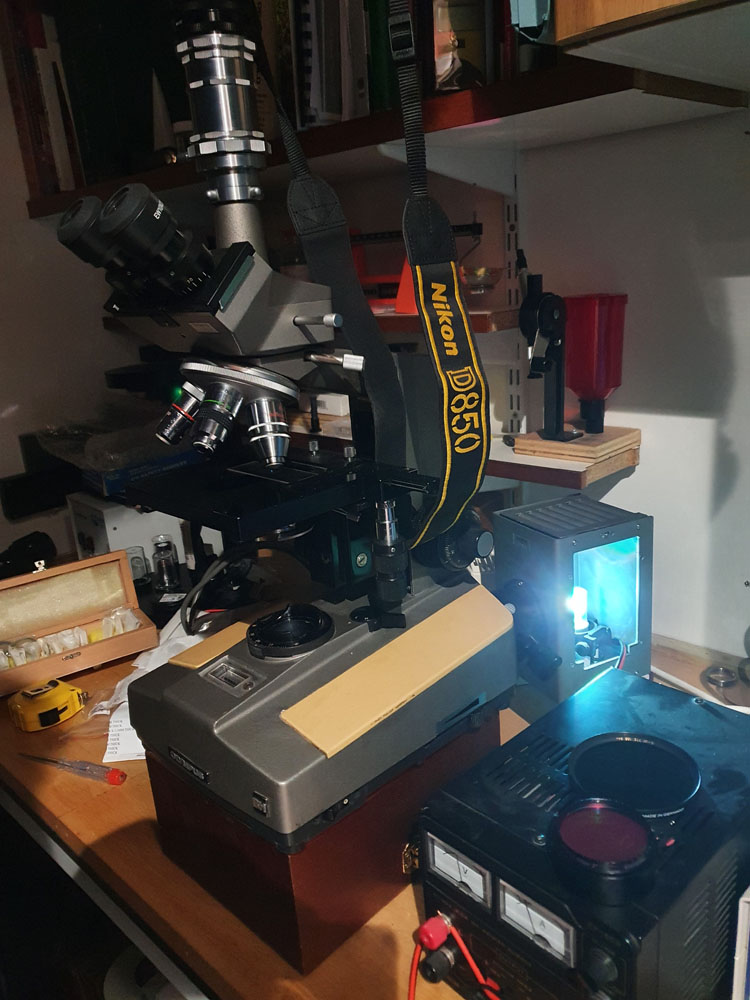
What about the light and setup? The lamp is a 3W low pressure mercury one, and was driven by a DC powersupply (manufacturer claimed 10VDC, but mine worked between at about 11V). Here’s a couple of pictures which shows the lamp and how it was setup on the microscope.
3W UVC lamp in action3W UVC lamp installed in the microscope
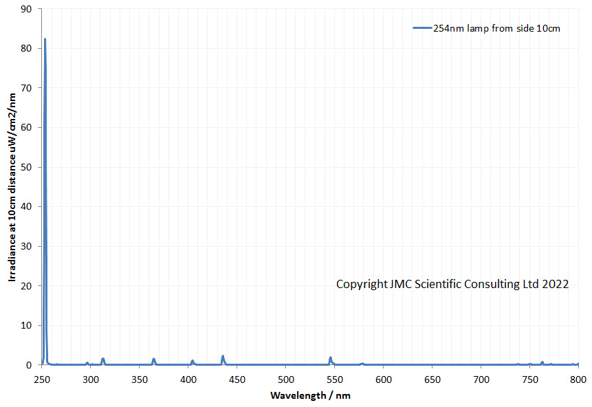
Also, here’s the emission spectrum from the lamp, showing the strong mercury emission line at just under 254nm (measured using an Ocean Insight FX spectrometer at a distance of 10cm from the side of the lamp).
Irradiance spectrum from the 3W UVC lamp
It’s early days for this experiment and hopefully there will be more news on it later in the year. For now though thanks for reading and if you’d like to know more about my work you can reach me here.