Yesterday I had an exciting parcel arrive – a set of microscope slides that I have had made for me by a very nice gentleman who I met during an ebay purchase (Opticsman0127, check out his slides here). I sent him some quartz slides and fused silica coverslips and he made me a set of slides with different diatoms on them for my UV work. These have been mounted dry using a bit of Debe’s mountant (gelatin) so as not to have the mountant absorb too much UV. Today I am sharing some images from one of the slides – a diatom strew – taken using 313nm light.
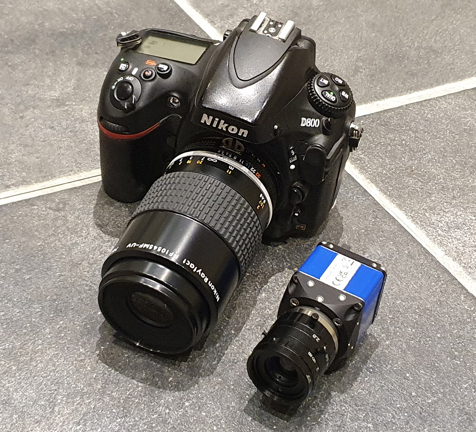
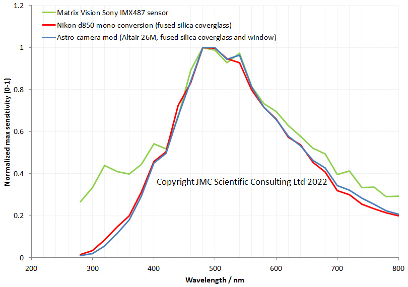
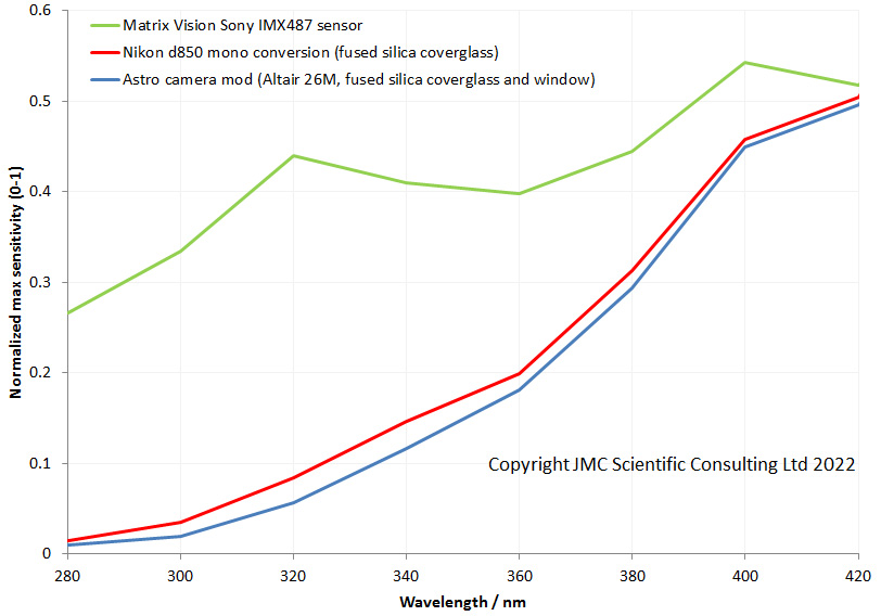
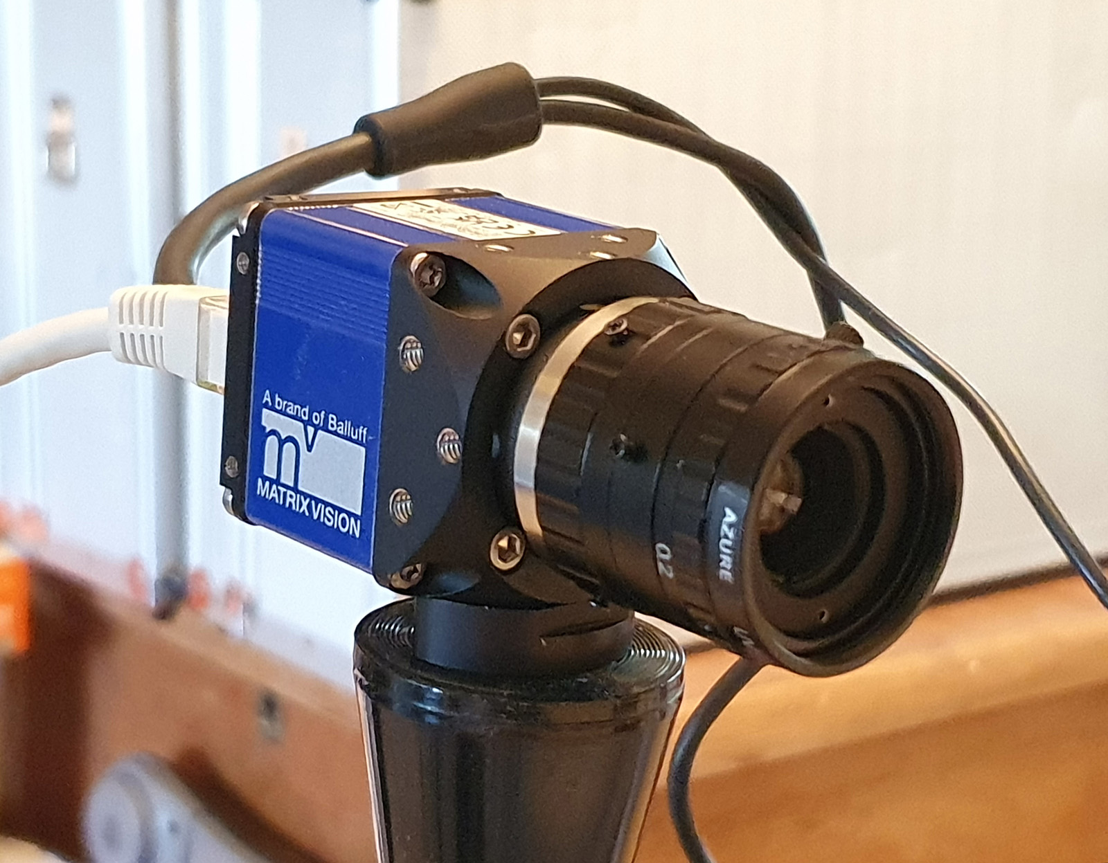
For these images I used a mercury xenon lamp and filtered the light to image at 313nm. The camera was my new Matrix Vision one with the UV sensitive Sony IMX487 sensor (see here for some images done at 254nm with it). I decided to use 313nm here as the light source I have which covers that wavelength is more powerful than my 254nm lamp, and I wanted to try a higher NA objective – a 100x Leitz NA 1.2 objective (see here for some information on that). Condenser was my antique Zeiss quartz one (NA 0.85) and the photoeyepiece is a Lomo quartz 8x one. The images are not stacks, but just single images taken in brightfield. I noticed that at this magnification there was some left/right movement in the images which would have complicated stacking. The images have been reduced in resolution for sharing.
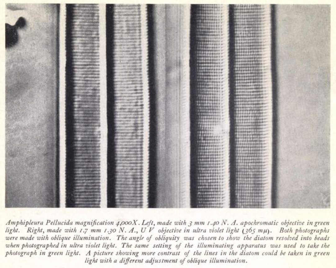
One of the really hard resolution tests for any microscope is the diatom called Amphipleura pellucida, as it has features of the order 200nm. This makes it extremely hard to image with normal light microscopy, and techniques such as cross polarized and annular oblique imaging are needed to see them even with objectives and condensers of NA 1.3 or more. I was trying this at 313nm with an NA 1.2 objective and 0.85 condenser (both using glycerine as immersion fluid) and normal brightfield, with a slide which just had a dry mount of gelatin. It’s a bit of a white whale for me as I have yet to get good images of it. Although I now have a slide I can do UV imaging with, this was always going to be fun.
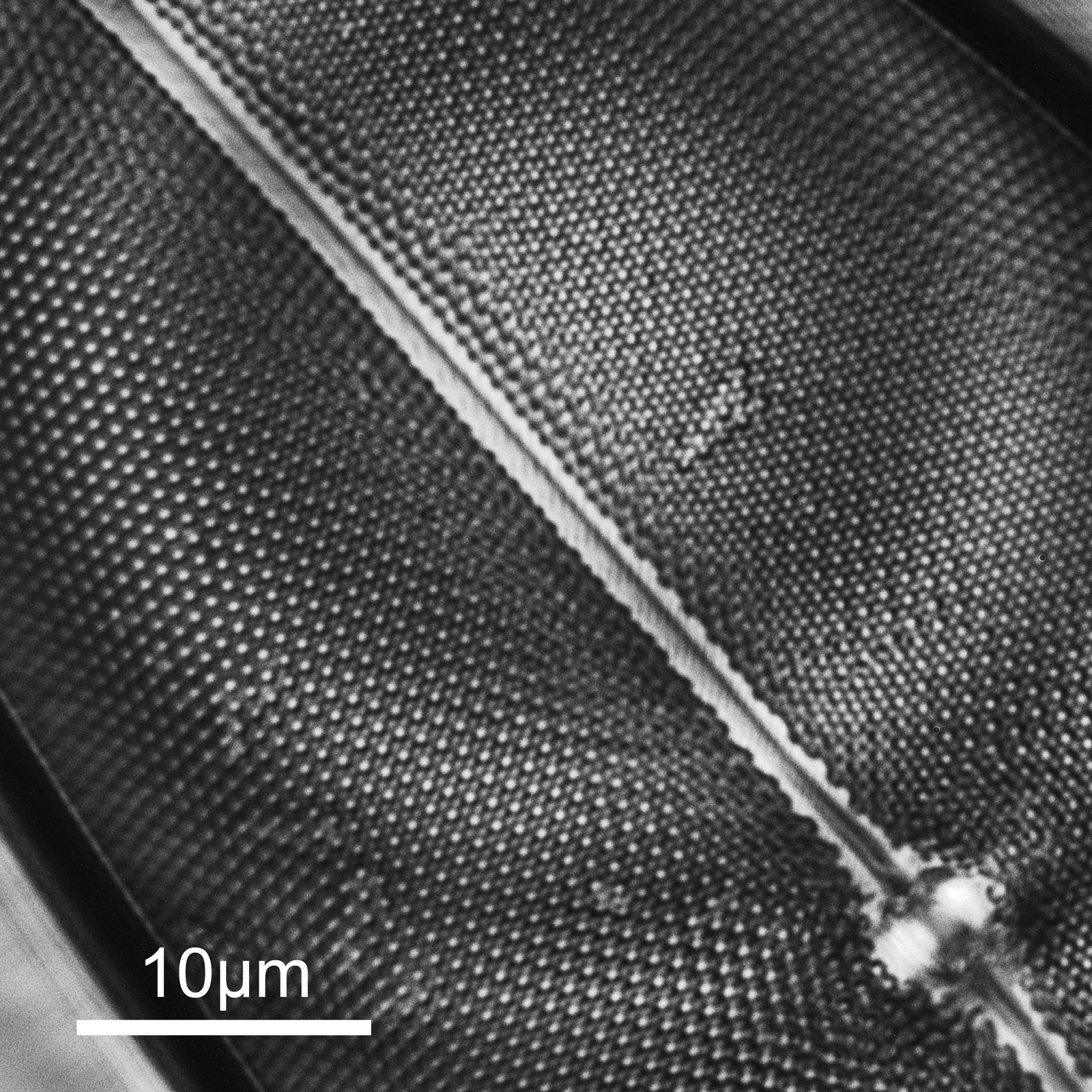
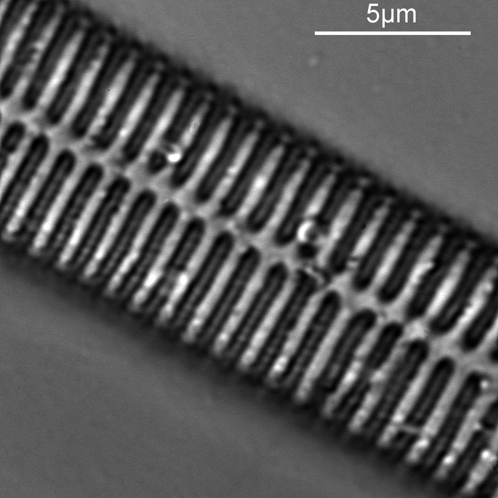
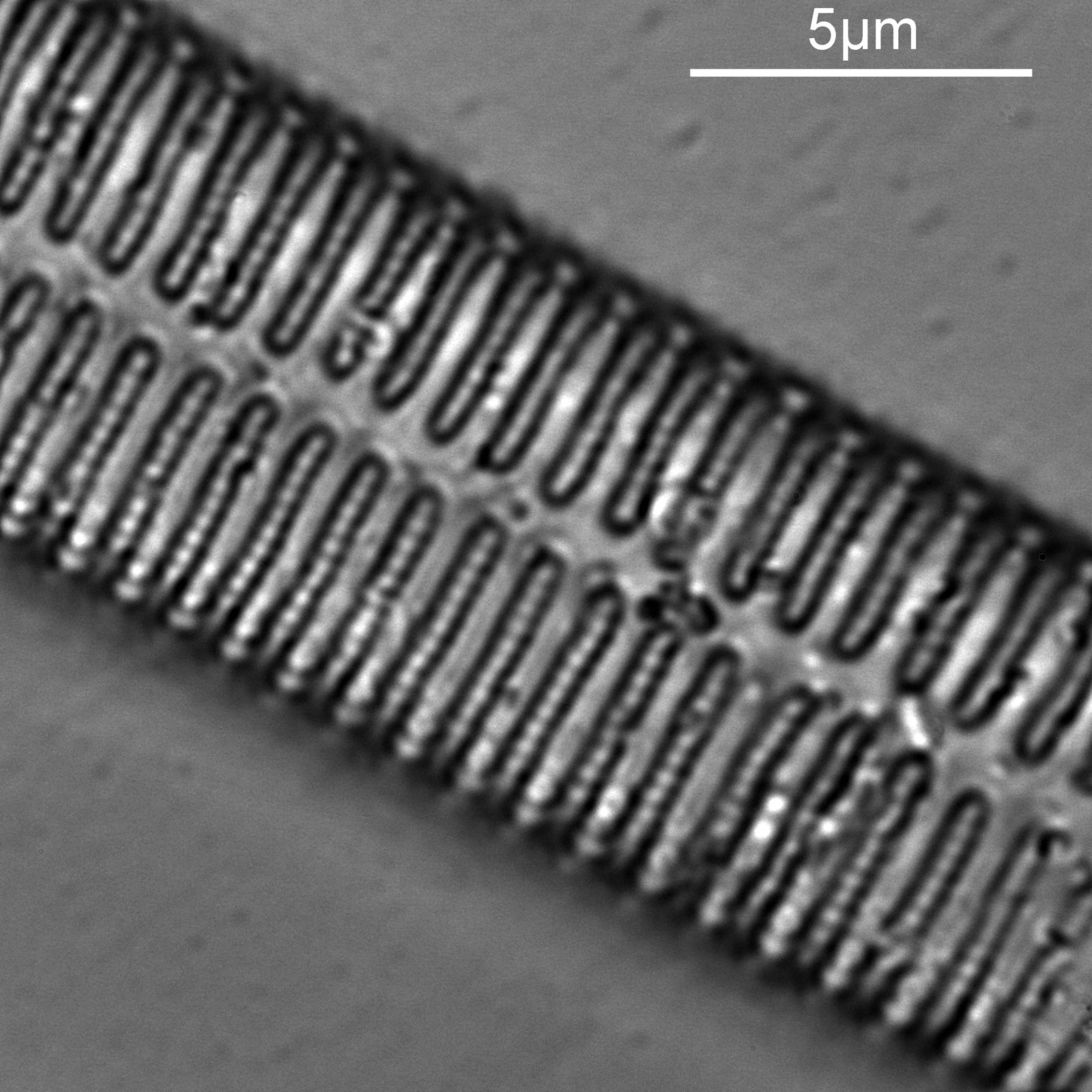
First a set of 3 images done at different heights within the A. pellucida diatom. The field of view is so small that only part of the diatom can be seen and it is close to one end of it.
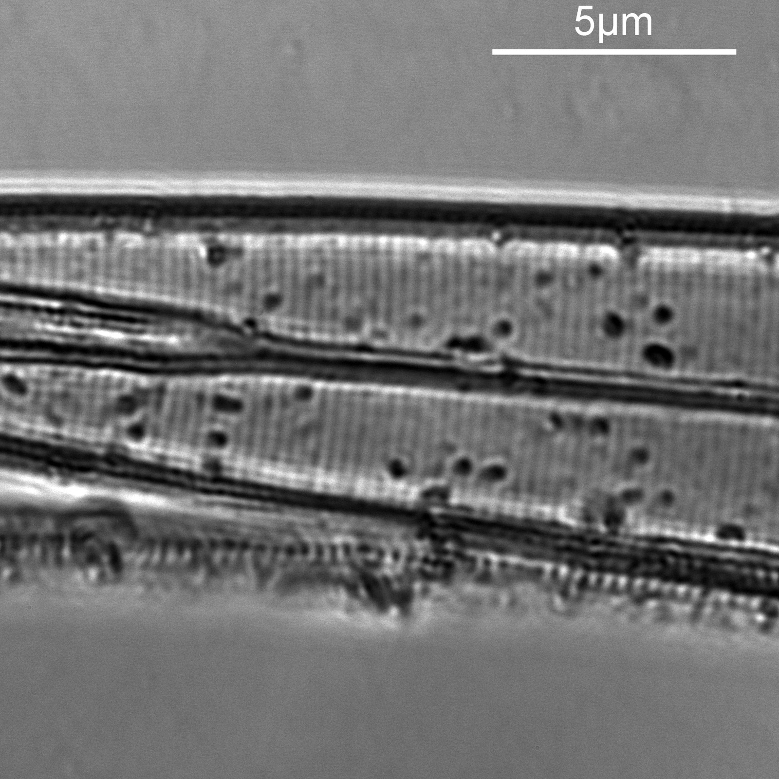

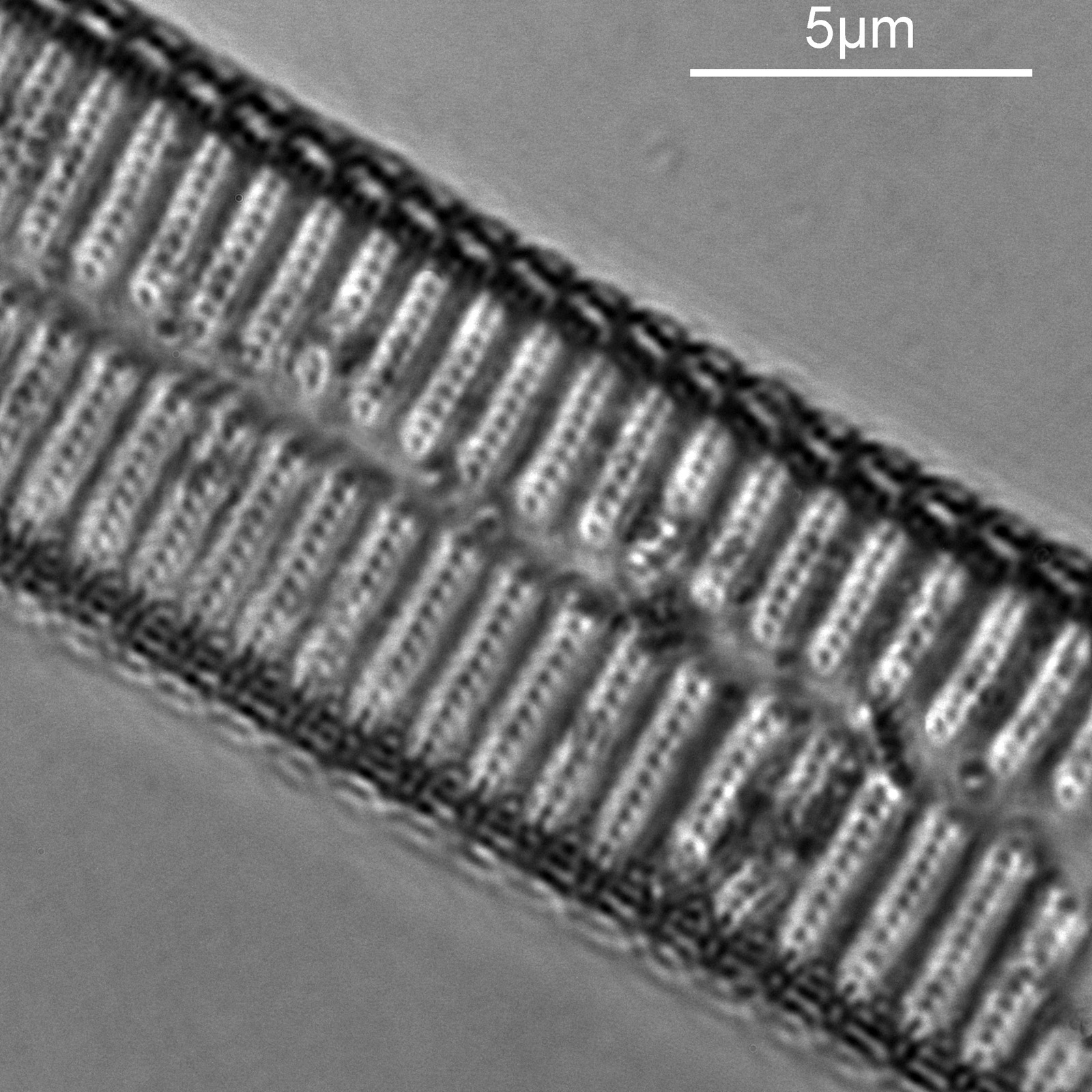
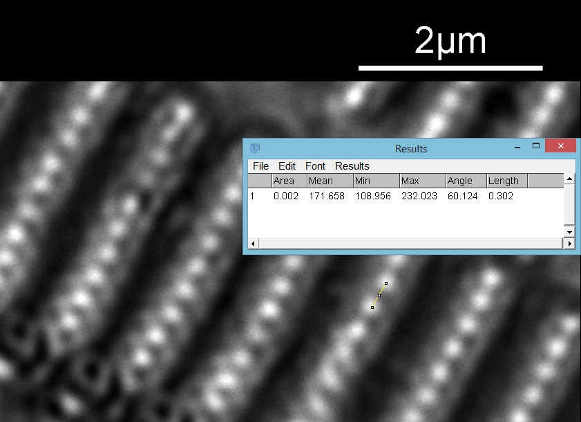
In the first two images above, there are faint vertical lines which become more visible in the second image. These are I believe called striae. In the third image, these lines start to break up and form a dot pattern. These are the punctae in the structure coming into focus. Let’s go in closer to the third image and have a better look. This is a crop from the image above, taken before the image was resized for sharing.
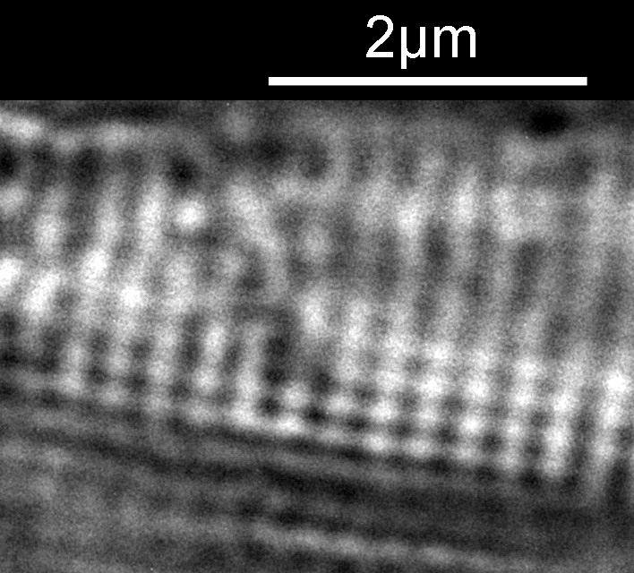
The regular dot pattern can be seen more clearly now. What is the spacing of these features? I put the image into ImageJ and did a couple of measurements. I have chosen to measure the distances between the dark spots, but it would be the same if I had chosen the white spots. First the distance between the striae.
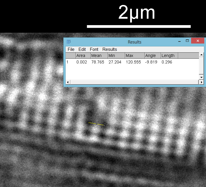
Then the distance between the punctae on a given stria.
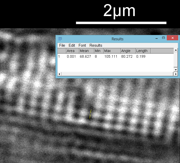
From this it looks like the striae are about 300nm apart and the punctae about 200nm, which is in keeping with SEM data I’ve seen on this species of diatom. This shows why they are such a challenge for the light microscopist. Even with the 313nm light being used here, I’d expect the maximum resolution obtainable with my setup to be between 135nm and 150nm depending on which calculation I use, so this is getting close to that.
Have I finally caught my white whale? While it is lovely to see the features on it, I wont stop trying to get better images, so I do not consider it caught just yet.
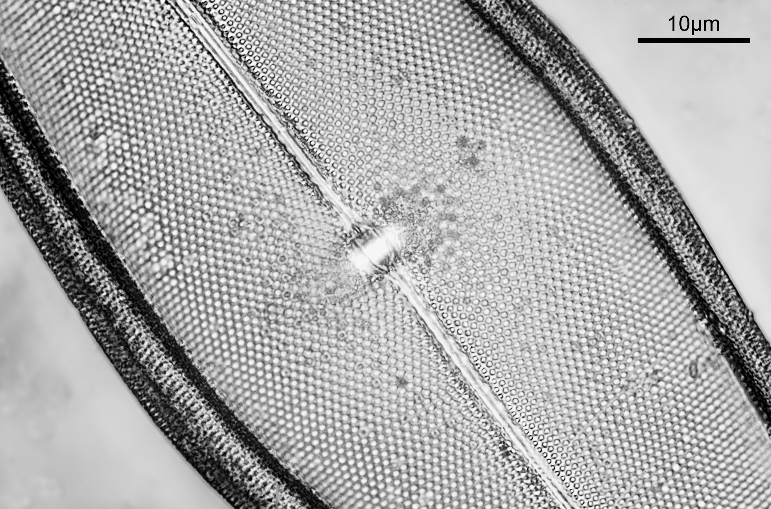
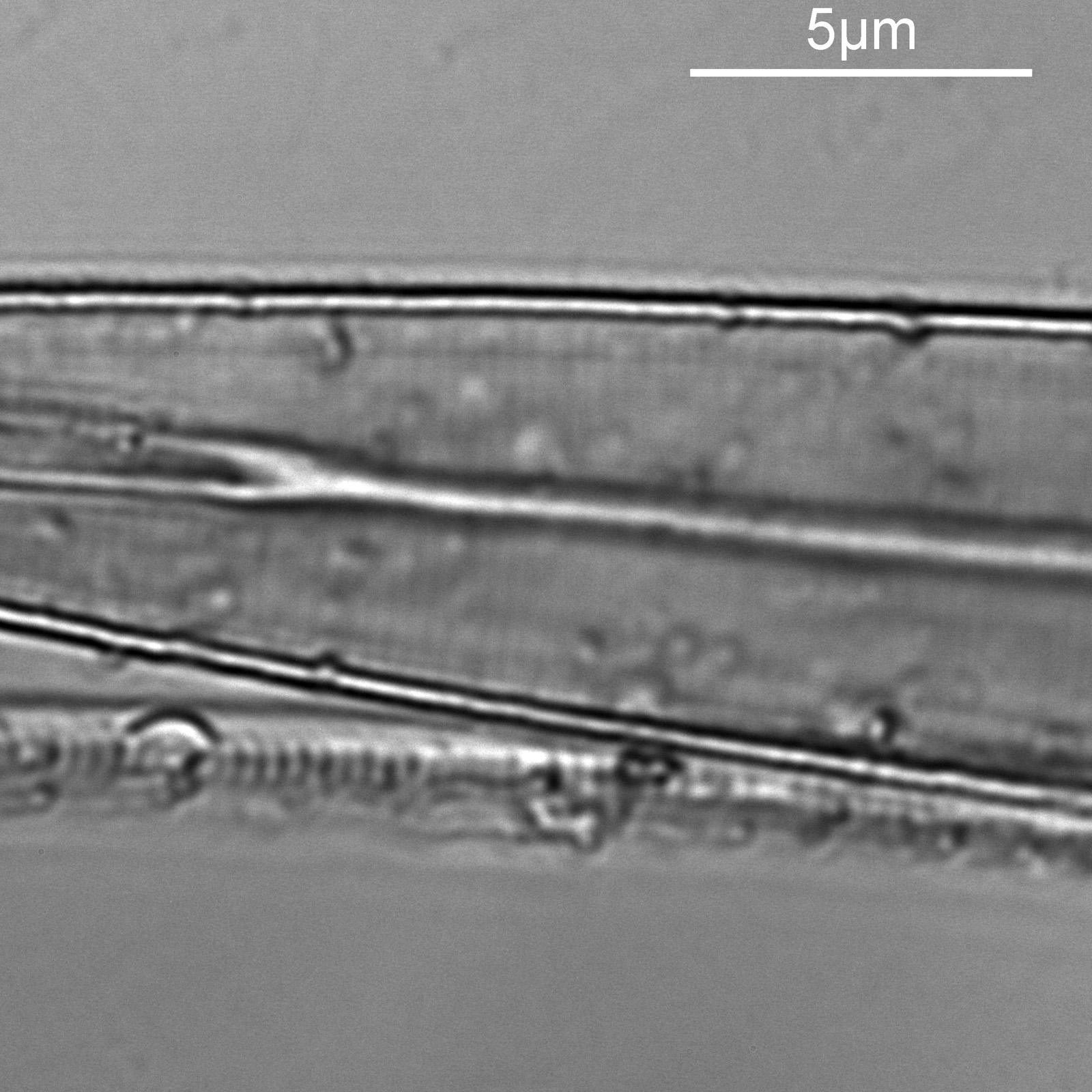
For the second diatom, I moved around the strew and found what I think is a diatom from the Synedra family, although I don’t know which one (if I find out I will update this). At this point it is worth highlighting one of the challenges I have found with using this new camera. The image below shows what I can see through the eyepiece of the microscope and was taken with the camera phone, with the 100x objective.

In the image above is a blue box. This is the approximate size of the image that the Matrix Vision camera sees when used with the 8x Lomo photoeyepiece and is about 16 microns square. As you can imagine it is a challenge even finding the subject with the camera as even the smallest touch on the stage causes it to disappear.
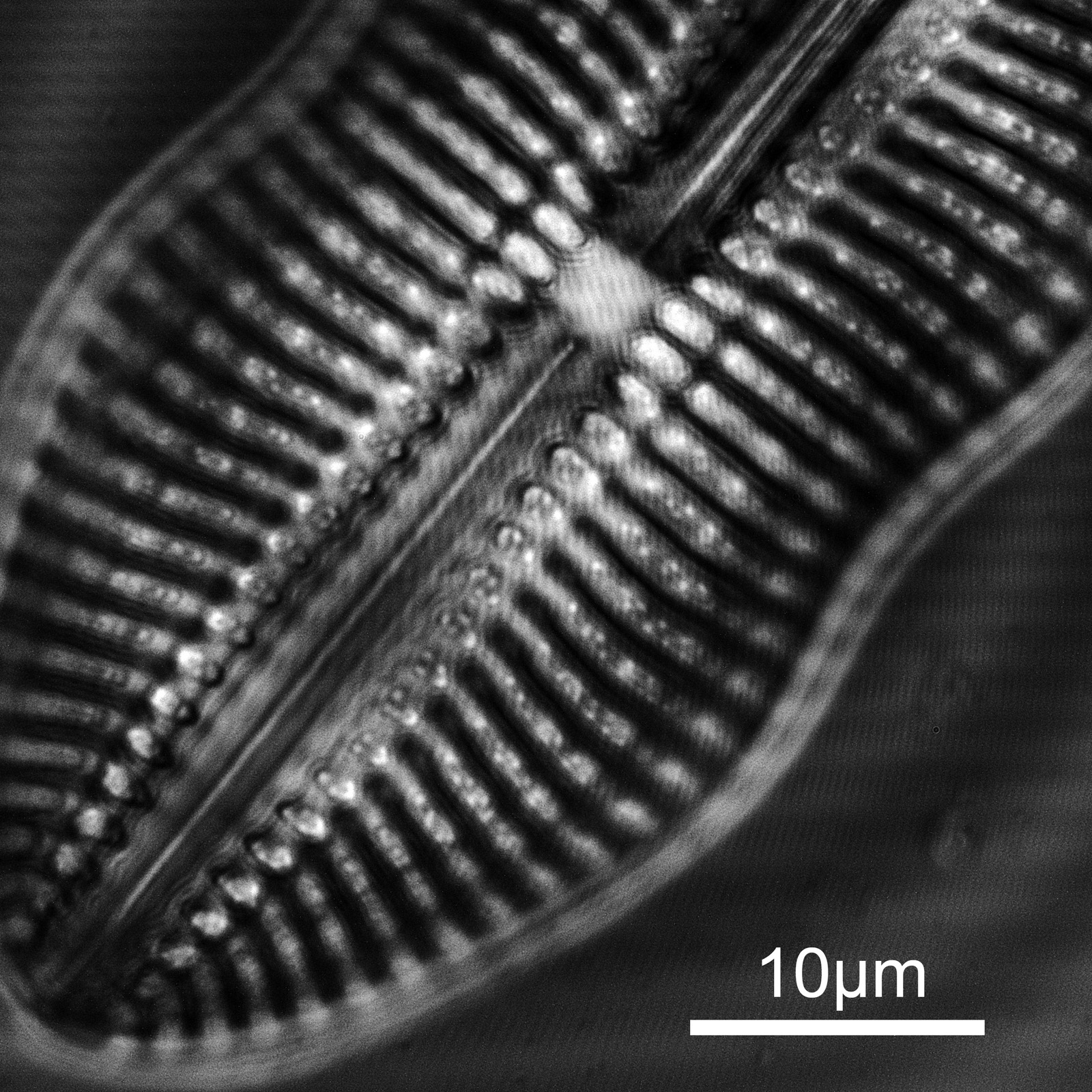
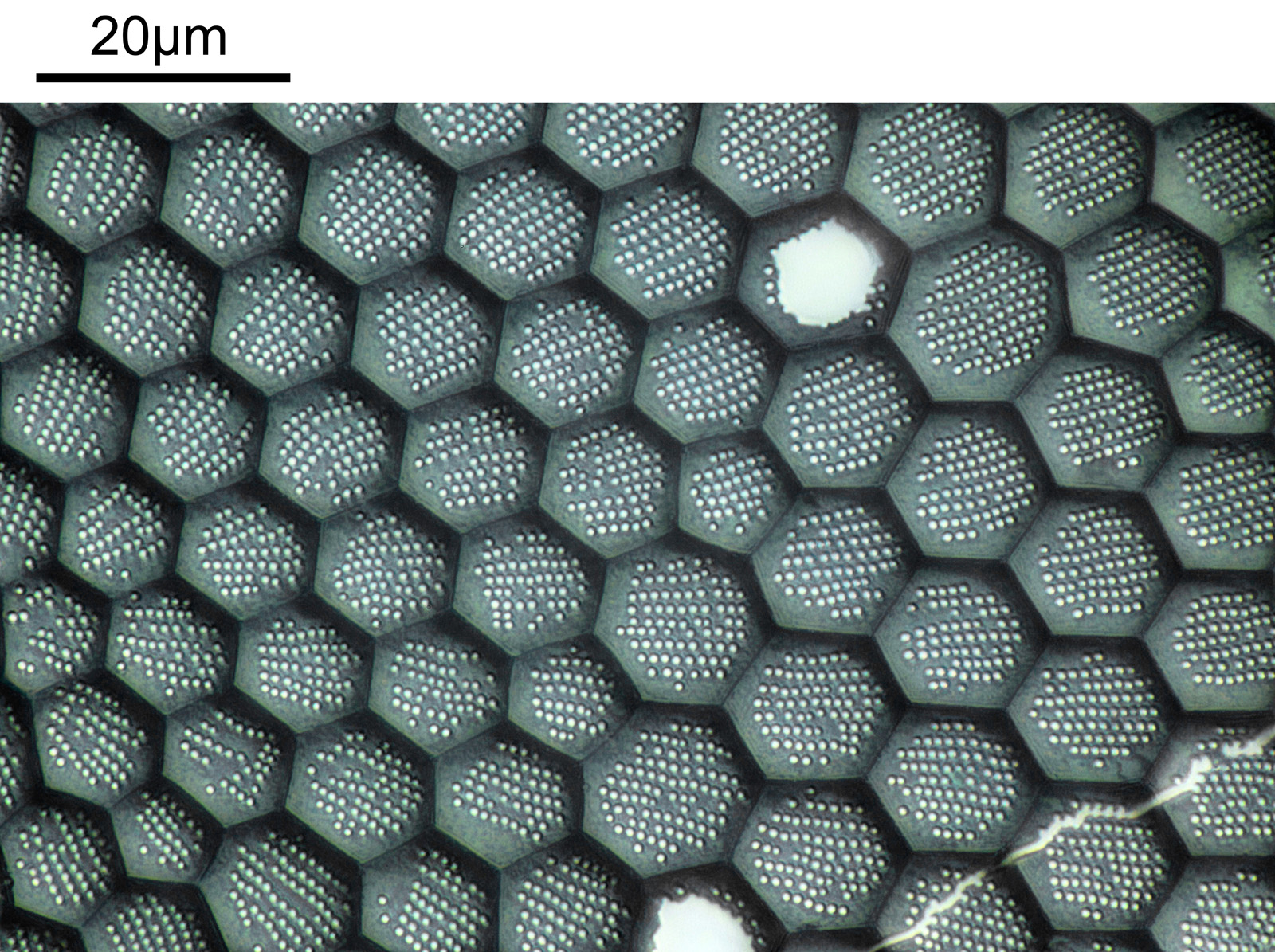
As before a series of single images showing part of the diatom taken at different focus heights.

As the diatom is moved up and the focus position varies, there are dramatic changes in the images, and the features which are visible. In the third image a series of bright dots appears in lines at 90 degrees to the diatoms central axis. As we go further, the dots reveal themselves to be what look like pits in the structure. Presumably these are holes in the structure, and with the focus at one position the light gets through, and when it is moved it cannot. Perhaps this is an interference effect given the wavelength being used and the size of the features?
As with the A. pellucida image, I took a crop of one of the images and put it into ImageJ to get some measurements on the distance between the dots.
On this diatom the dots look at be about 300nm apart.
Where has this new work taken me? The Matrix Vision camera continues to impress me, and live view at 313nm enabled me to focus down to fractions of a micron to get the images (the camera is so sensitive, I was able to do live view imaging at about 1s exposure to get the focus right). The field of view is tiny though, so I need to go back and re-evaluate some of the my other quartz photoeyepieces to see if I can find something which presents a wider image to the camera. At the moment the pixel resolution with this setup would be about 178 pixels per micron (5.6nm per pixel). Given the max resolution I would expect is about 130nm, that means I am wasting a lot of the resolution. A photoeyepiece which gives a wider field of view would help here, giving me both a larger area being imaged, while hopefully not compromising actual resolution. More work needed here in the future. 254nm illumination should be even more impressive than 313nm, but my current homemade light source is not powerful enough to use with this objective so that will be another job for 2023.
Before I go, a quick photo of the slide itself.

I look forward to spending plenty of time on this and the other slides in 2023. As always, thanks for reading, and if you’d like to know more about my work I can be reached here.