Having the right tool for the job. It is important when doing measurements that we have access to the right techniques (and of course know how to use them – a fool with a tool is still a fool). When characterizing optical filters, I’ve normally just done transmission measurements. However with some filters they have dichroic coatings present on them which can reflect unwanted wavelengths of light even before the light passes through the filter. While I had tried doing some basic measurements of reflectance from these types of filters before, the results were never optimal. I recently decided to bite the bullet and order a proper reflectance probe so I could do this type of work in a more controlled manner. Today I’ll be sharing some initial data from it.
The probe I went for was one by Ocean Insight. They worked with me on the design which is always good when a company does that, and it arrived about 3 weeks after ordering it. I needed one which would work from the UV (250nm) to the IR (1100nm) to match the spectrometers and light source I have, and because those are the wavelengths which are most relevant for photography with normal cameras. I also needed it to be the right diameter for me to use on my Ocean Insight RTL-T stage. The incoming light illuminates the sample through 6 fibers arranged around a 7th one in the middle which is the one which goes to the spectrometer. I have an Ocean Insight FX spectrometer and an STS-NIR one as well, so can measure between 250nm and 1100nm by using the two devices.
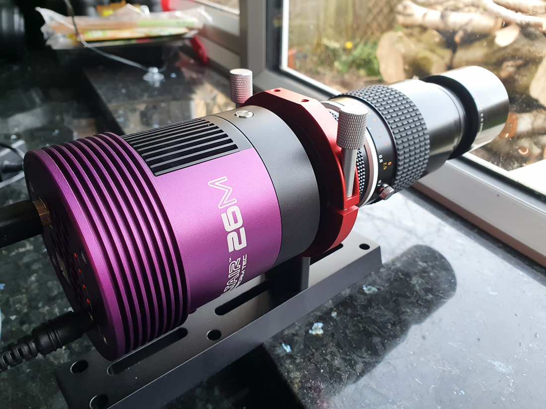
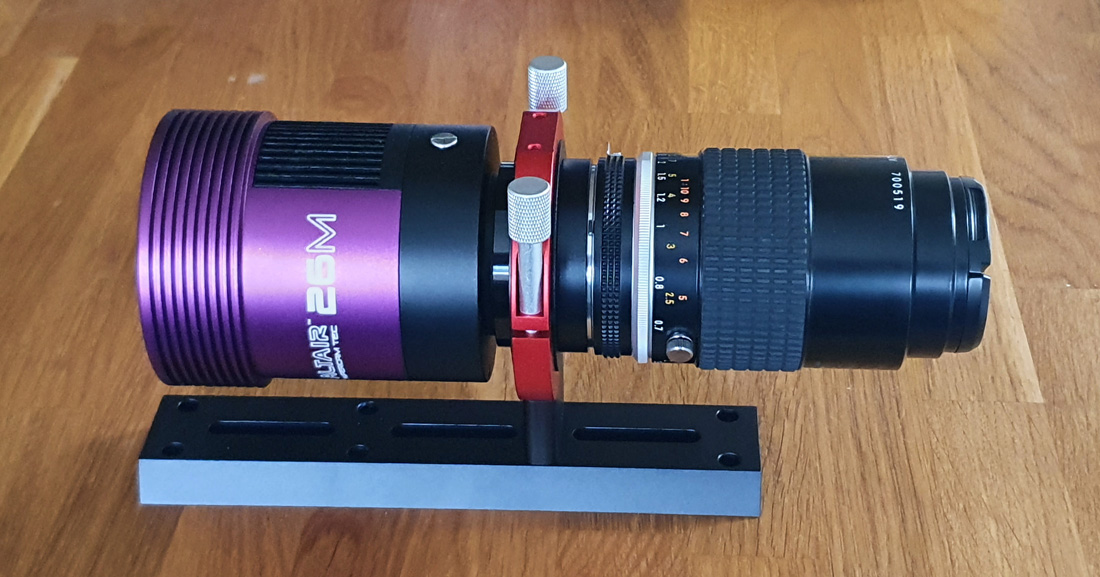
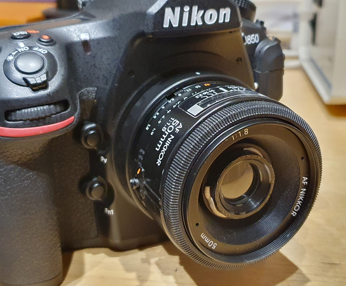
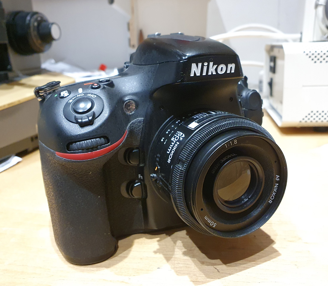
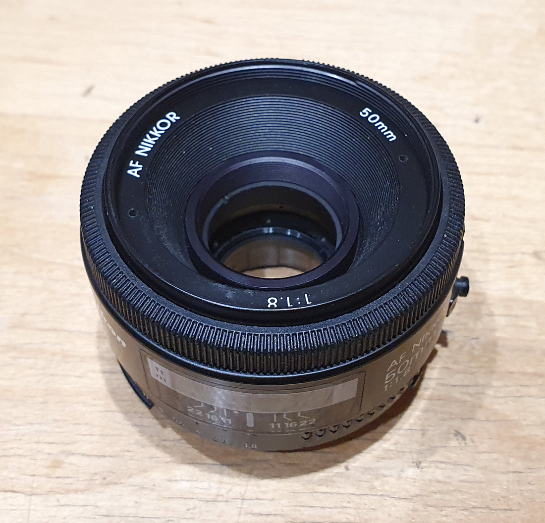
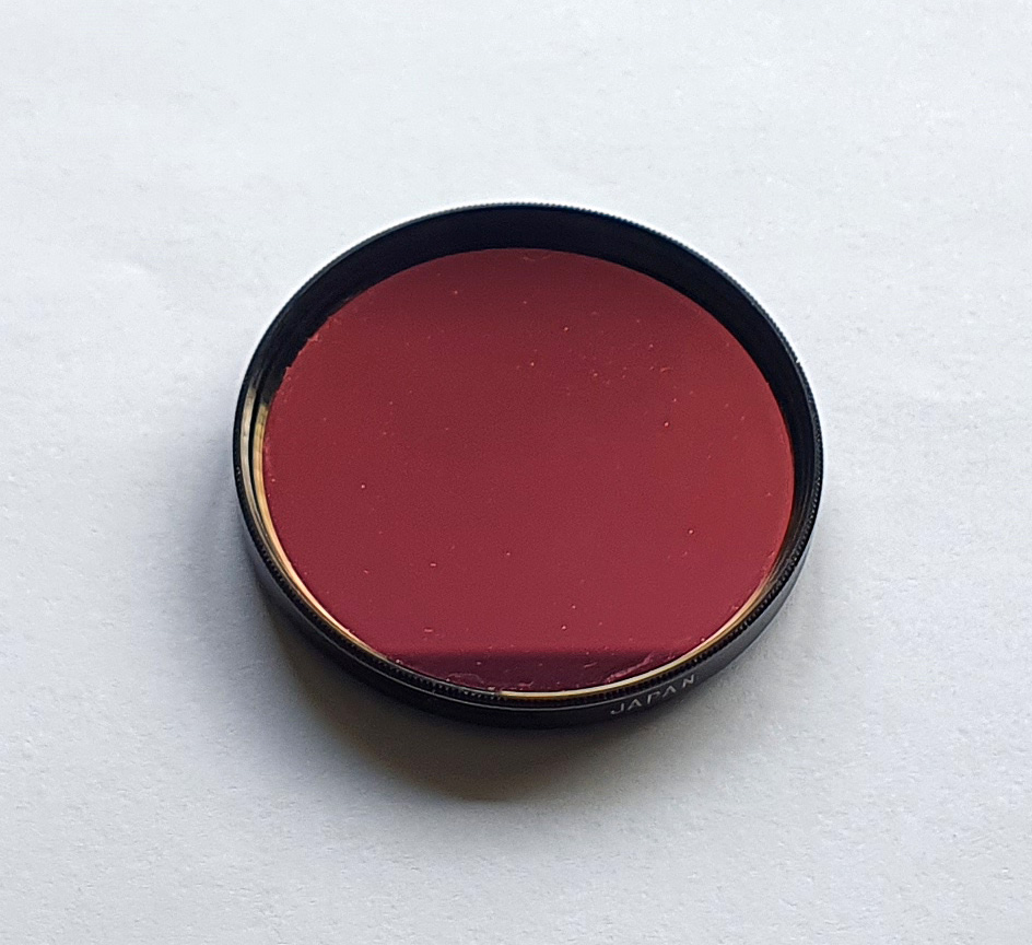
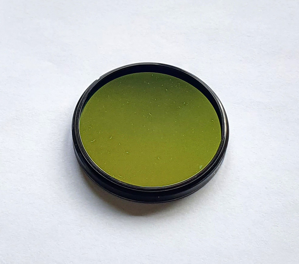
For a test filter I use a Baader U, which is a UV pass filter commonly used for UV photography. It has good blocking of unwanted wavelengths, and importantly for me, dichroic coatings on both surfaces which look different to each other. On mine one side is red/pink, and the other green/gold and I have remounted it in a 49mm filter thread for using on my camera lenses (see below).
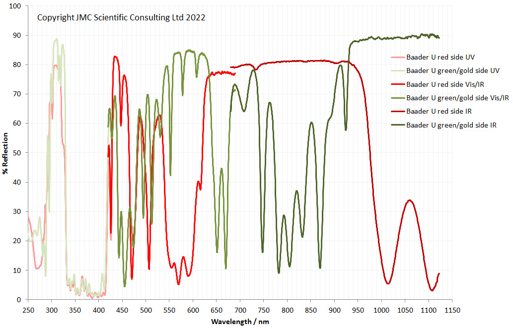
What do the filter coatings look like in terms of reflectance? Combining the measurements from both sides using both spectrometers gives the following rather complicated graph;
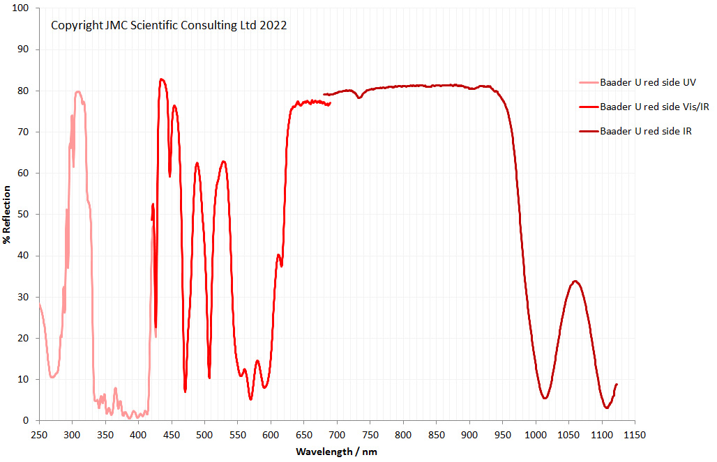
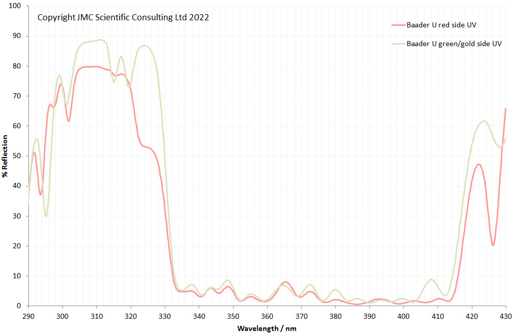
It’ll be clearer to show each side individually. First the red/pink side;
And the same from the green/gold side;
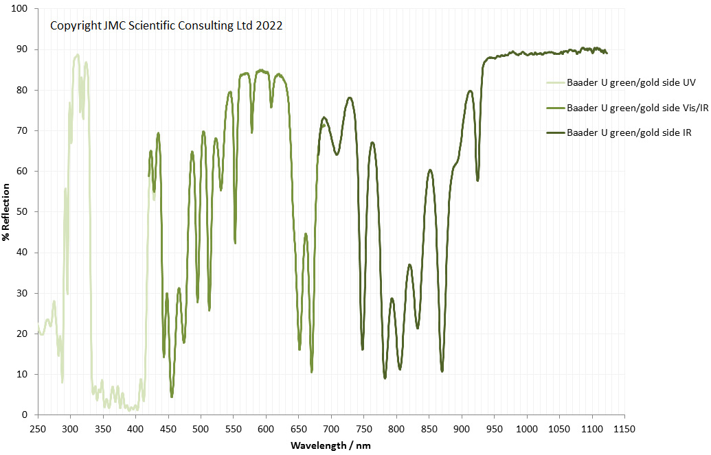
There are some big differences in terms of the reflectance from the two surfaces of the filter, especially in the red/IR region. The red side has the better blocking from 600nm to 1000nm, while the green/gold side has better blocking above 1000nm. It is common practise when using these filters for UV photography to reverse the filter compared to how it is normally supplied. This is because the mounting on a camera lens would naturally reverse it compared to mounting it on a telescope (one uses a female thread the other a male). In UV photography when using it in a camera and not a telescope it is recommended (by fellow UV photographers) to mount it with the red/pink side facing the subject. This makes sense as it presents the side which reflects the most red/IR before it can even enter the bulk interior of the filter.
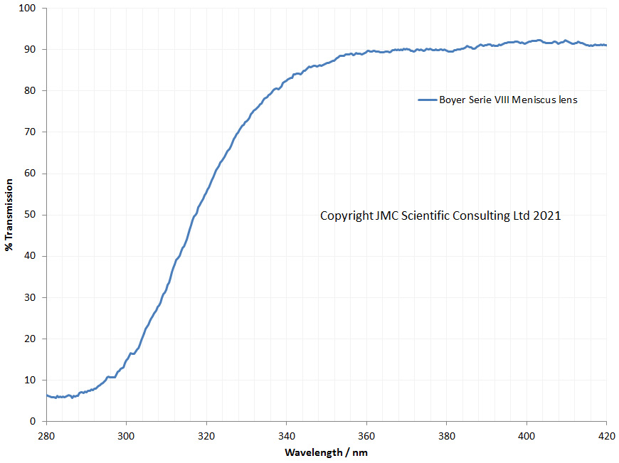
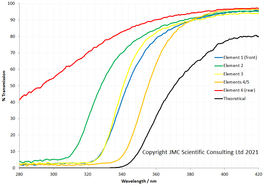
The filter itself is used for UV photography, and has good transmission between about 330 and 400nm. The coatings on both sides are designed for this, as they both have very low reflectance in that region;
I have deviated slightly from the normal approach for using this probe, and will explain why now. Normally when using this probe, Ocean Insight would recommend using a high reflectance specular reflection standard for calibrating the spectrometer before the measurement. However this does vary in reflectance across the wavelength range, and I could not justify the cost. Instead I bought two mirrors from Thorlabs – a UV enhanced aluminium one, and a protected silver one. I use the UV enhanced one for UV measurements and the protected silver one for visible and IR measurements. They offer very similar properties to the Ocean Insight specular reflectance standard and were about 20% of the cost. If I needed a NIST traceable standard I’d invest in a proper one, but for my work, these mirrors will be sufficient. It should be remembered though that the % reflection scores are vs the mirror, and that does vary slightly in reflectance at different wavelengths. This is one reason why full experimental details are needed whenever reporting data.
As always, thanks for reading, and if you’d like to know more about this or any other aspect of my work, you can reach me here.