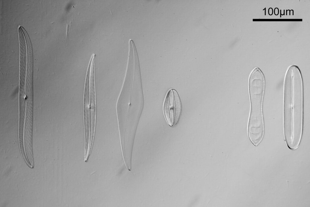
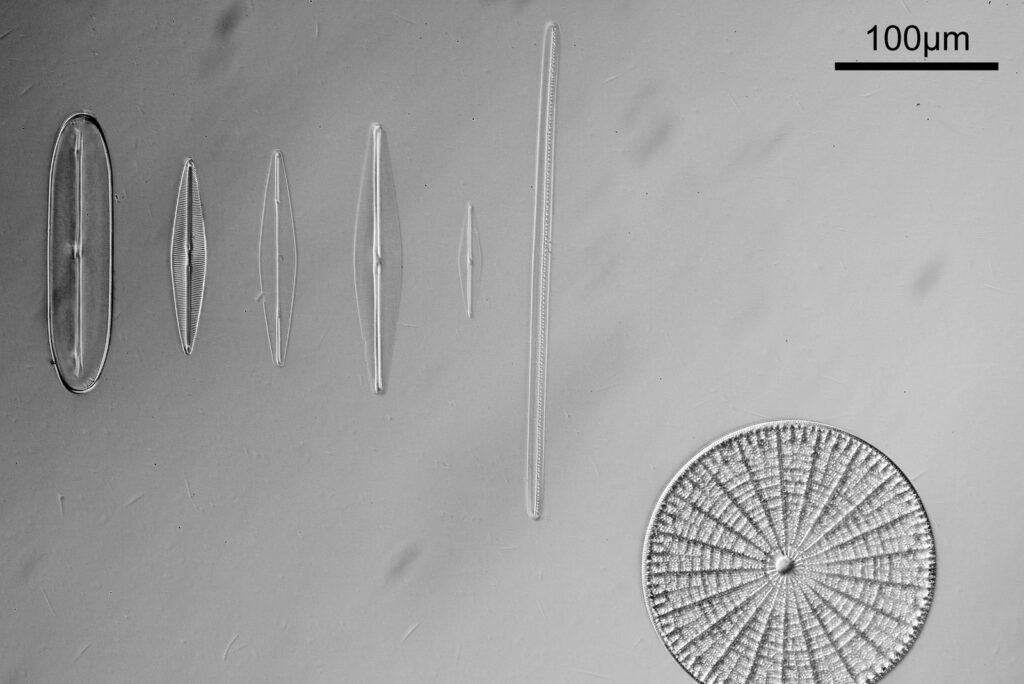
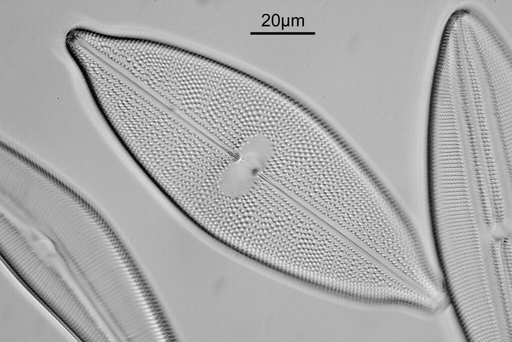
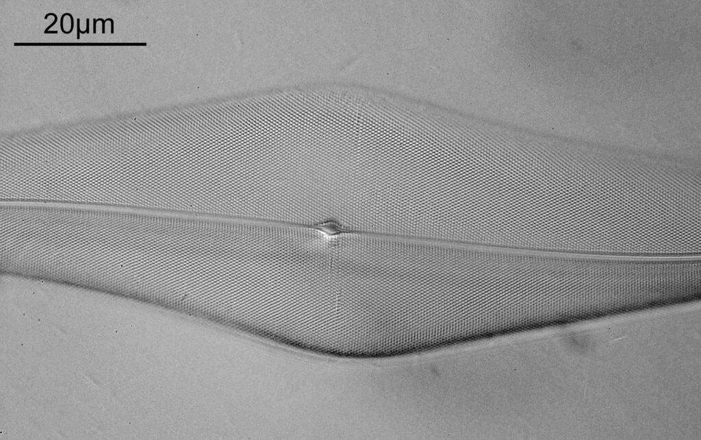
All posts by Jonathan Crowther

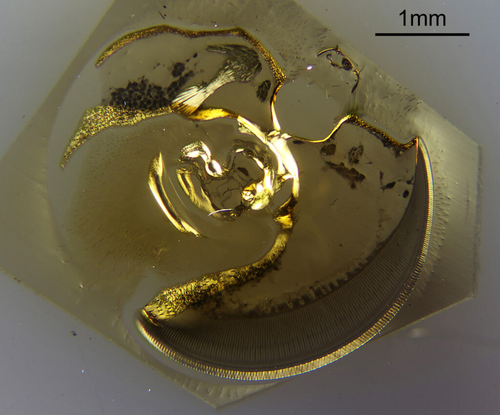
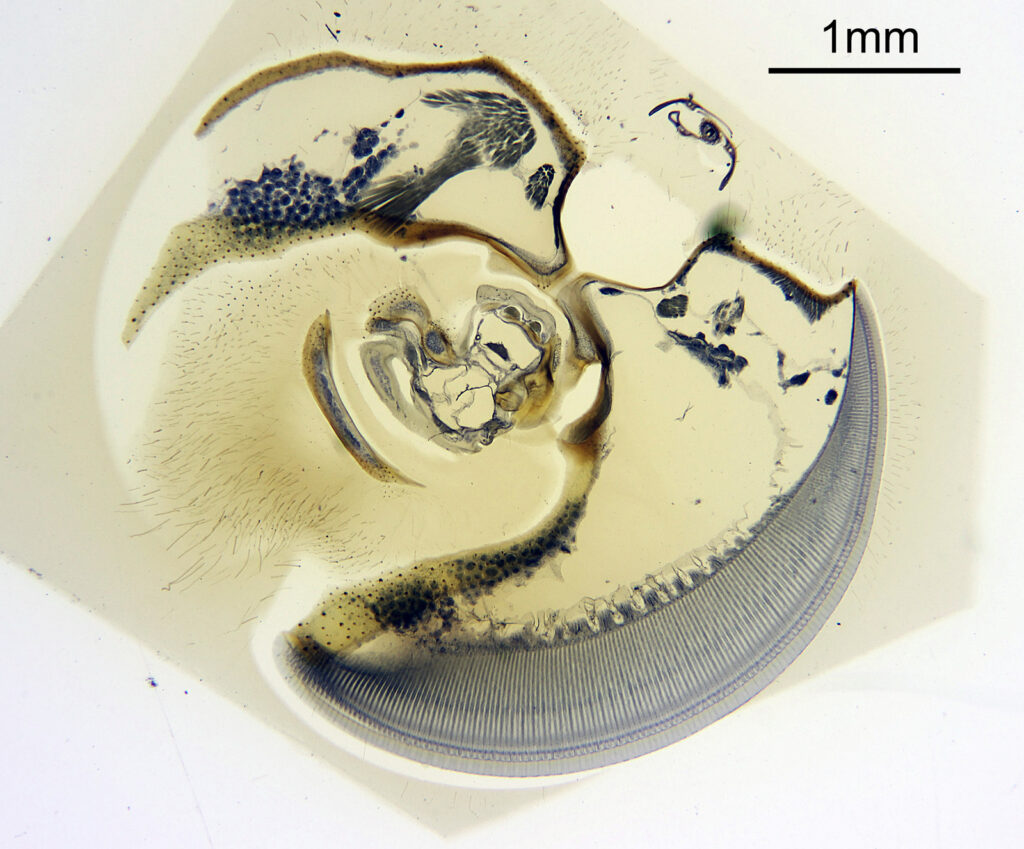
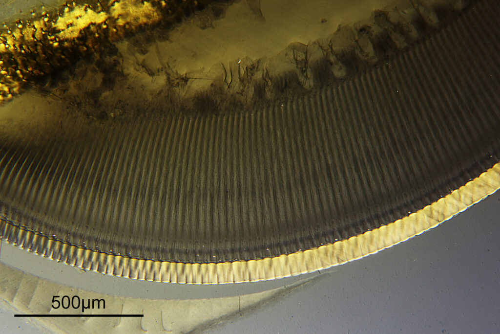
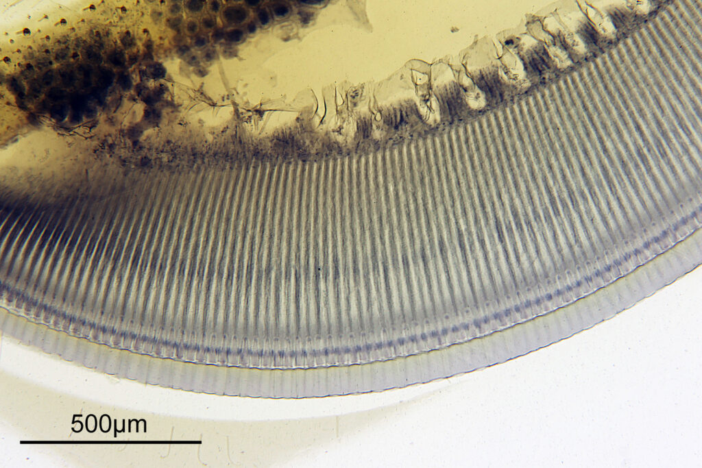
Microscopy – Horace Dall Soldier Beetle slide in visible and IR light

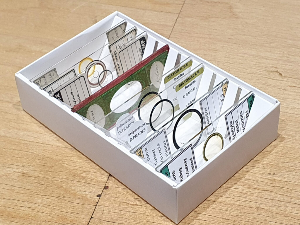
For those who frequent my blog, you’ll have heard of the slide maker Horace Dall before. I’ve been a keen collector of his metal and metal oxide coated diatom slides for a while (and am currently writing an article on them which I hope to publish later this year). I recently came across a slide of his for sale which was a bit different though – not a diatom slide but a whole Soldier Beetle. Today I’ll share some images from this slide using both visible light and Infrared (IR).

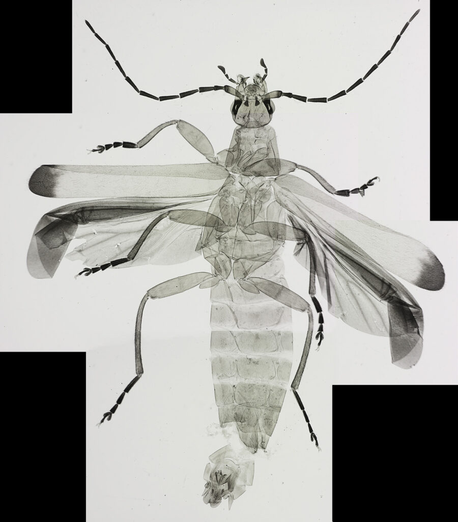
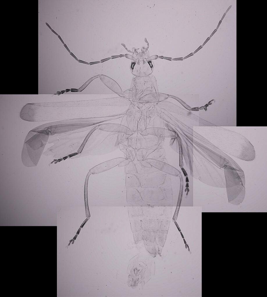
With diatoms, I normally have to go to high magnification to see them. However with this slide the problem I had was going to a low enough magnification, as the whole sample is about 20mm across. To image the whole beetle, I took 4 images using a 1x Olympus Splan Fl objective and stitched them together in Photoshop. Here’s what the sample looks like (resolution has been dropped from the original 9390×10687 to 1600×1821 for sharing).

Horace Dall Soldier Beetle slide. Composite of 4 images using a 1x Olympus Splan Fl objective

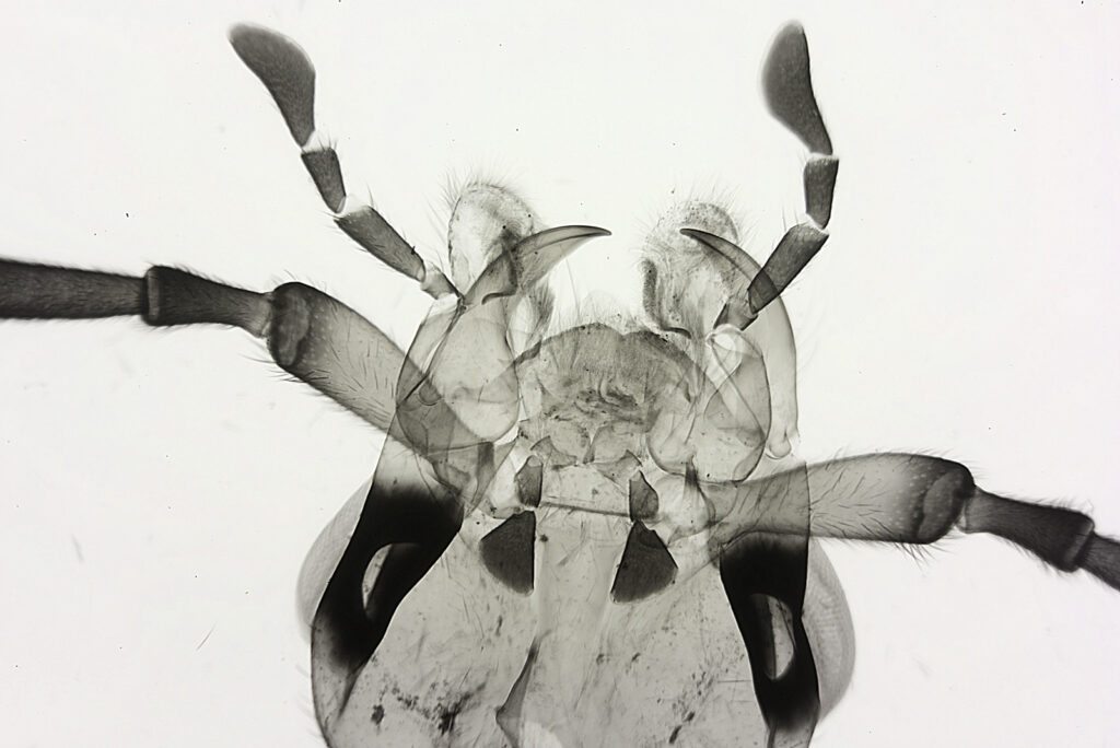
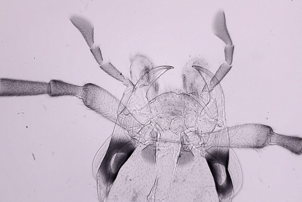
A higher magnification image of the head of the beetle using a 4x Zeiss Planapo objective.

4x Zeiss Planapo image of the head of the Soldier Beetle

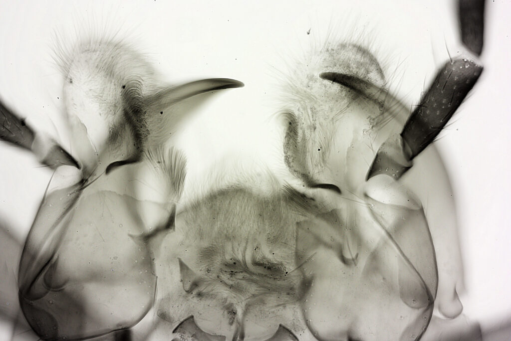
And to finish with a couple of images using a 10x Olympus UVFL objective.

10x Olympus UVFL objective image of the Soldier Beetle head
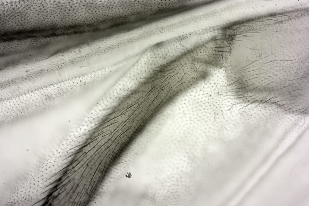
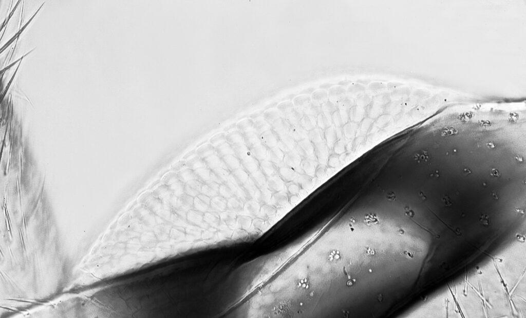
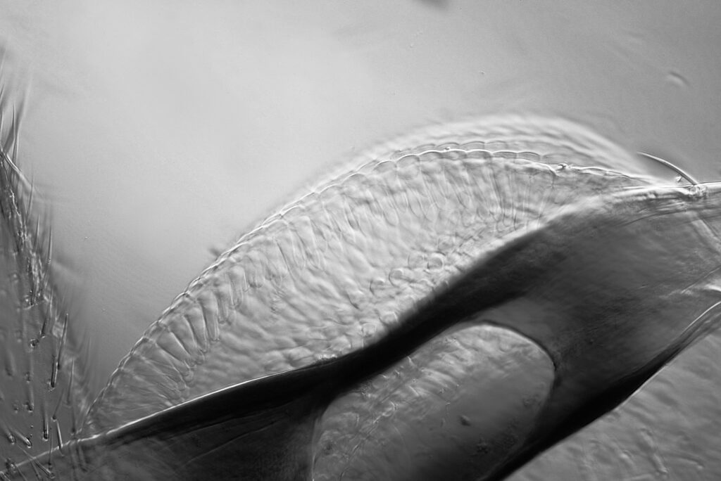
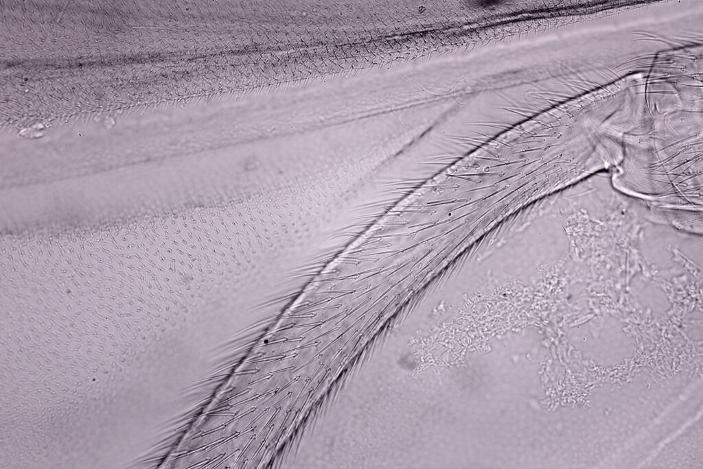
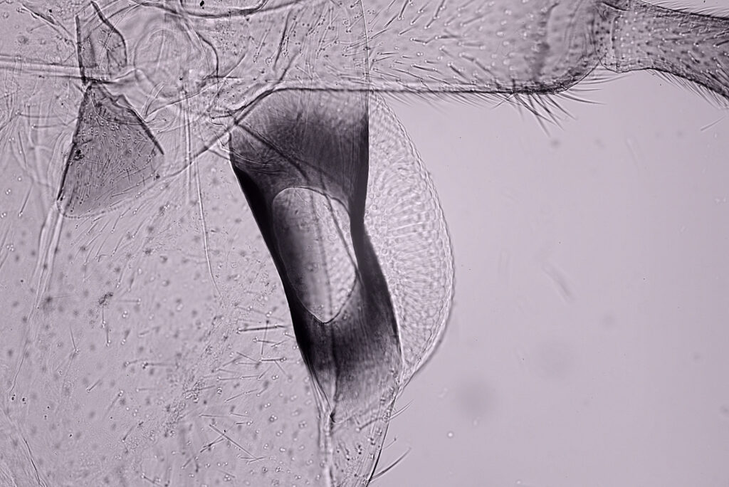
10x Olympus UVFL image of part of the wing and leg of the Soldier Beetle

While chatting with a friend on a microscopy forum he mentioned to me that IR light can be useful for imaging insect microscope slides as it makes some parts become more transparent. To try this out I swapped the LED light source for a Tungsten bulb, and placed a Heliopan 780nm long pass filter over the field lens, and then imaged the slide again.

Here’s the composite of 4 images using IR light (the IR images have a slight pink tinge in the JPEG for straight from the camera).

Horace Dall Soldier Beetle slide. Composite of 4 images using a 1x Olympus Splan Fl objective and using IR light

The IR light does indeed make parts of the insect appear more transparent, and the overall effect is to produce a lower contrast image. Next up the head using the 4x Zeiss Planapo objective.

4x Zeiss Planapo image of the head of the Soldier Beetle using IR light

Again, the increased transparency if obvious. Finally some images using the 10x Olympus UVFL objective.

10x Olympus UVFL objective image of the Soldier Beetle head using IR light
10x Olympus UVFL image of part of the wing and leg of the Soldier Beetle using IR light
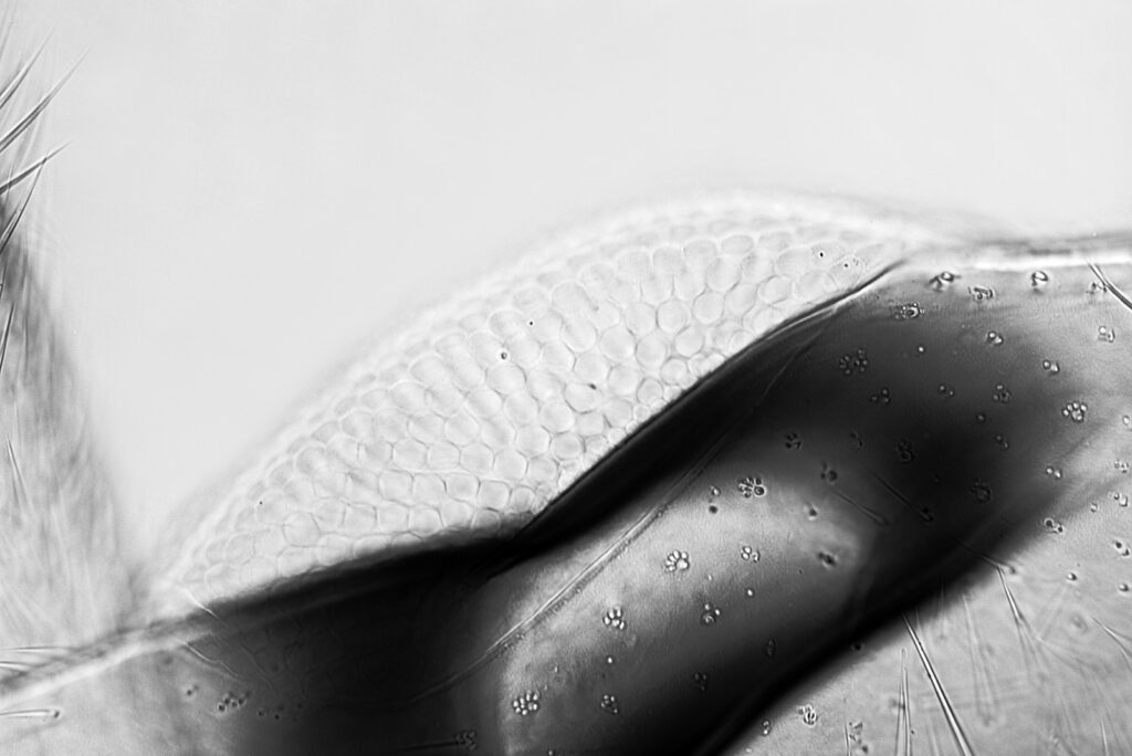
10x Olympus UVFL image of the eye of the Soldier Beetle using IR light

I did an additional image here of the eye with the 10x objective. The IR cuts through the darkly pigmented area and shows more of the structure of the eye. I think I need to come back to this with a higher magnification and try a stack. The 10x objective has a bit of a hotspot in the middle of the image in the IR photos. This behavior is often seen in IR photography when the lenses aren’t suitable for IR, and I presume that is the case here.

As a final set of images, I thought I would try imaging the eye region in IR with a 20x objective (a 20x Nikon Plan Apo NA 0.65). 3 different images are shown here; a single image at a given focus point (bright field), a stack of 4 images (bright field), and a single image using oblique bright field. These images were desaturated to remove the pink tinge from the IR images.

20x objective, single image, bright field, IR
20x objective, stack of 4 images, bright field, IR
20x objective, single image, oblique bright field, IR

The single image using the 20x objective shows a surprising amount of detail especially in the surface of the eye. The stack of 4 images shows even more detail and some of the tubular structures of the eye lens elements. The oblique image is more of a cross section through part of the eye but does nicely highlight the structure of the individual lens elements. Interestingly this 20x Nikon Plan Apo seems to have very little hotspot in the IR so could be a good one to use again in future.

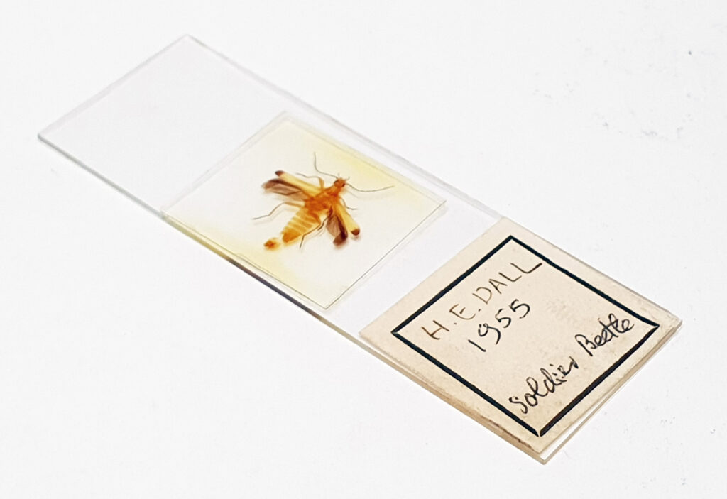
As per usual here’s an image of the slide as well.

Soldier Beetle slide by Horace Dall

Every now and then it is nice to have a break from imaging diatoms and look at a different sample. By moving from visible light to IR it was possible to seem through some of the dark areas of the beetle’s structure. Thanks for reading, and if you’d like to know more about my work I can be reached here.

Photography – Infrared imaging with the Zeiss ZF-IR 25mm and 50mm lenses

While most of my imaging outside of the visible spectrum is in the Ultraviolet, I do also like to take photographs at the long wavelength end in the Infrared (IR), especially for landscapes. Many lenses suffer from hotspots when used in the IR adding complexity when processing images. A few years ago Zeiss released their ZF-IR lenses (25mm, 50mm and 85mm) which had coatings on them to produce better IR transmission and reduce hotspots. These lenses weren’t available for long before Zeiss stopped selling them and they have now reached something of a cult status making them hard to find (and expensive) second hand. I recently managed to source examples of the 25mm f2.8 and 50mm f1.4 ZF-IR lenses from the photography dealer Jo Geier at Mint and Rare in Austria, and today I wanted to share some initial thoughts on them.

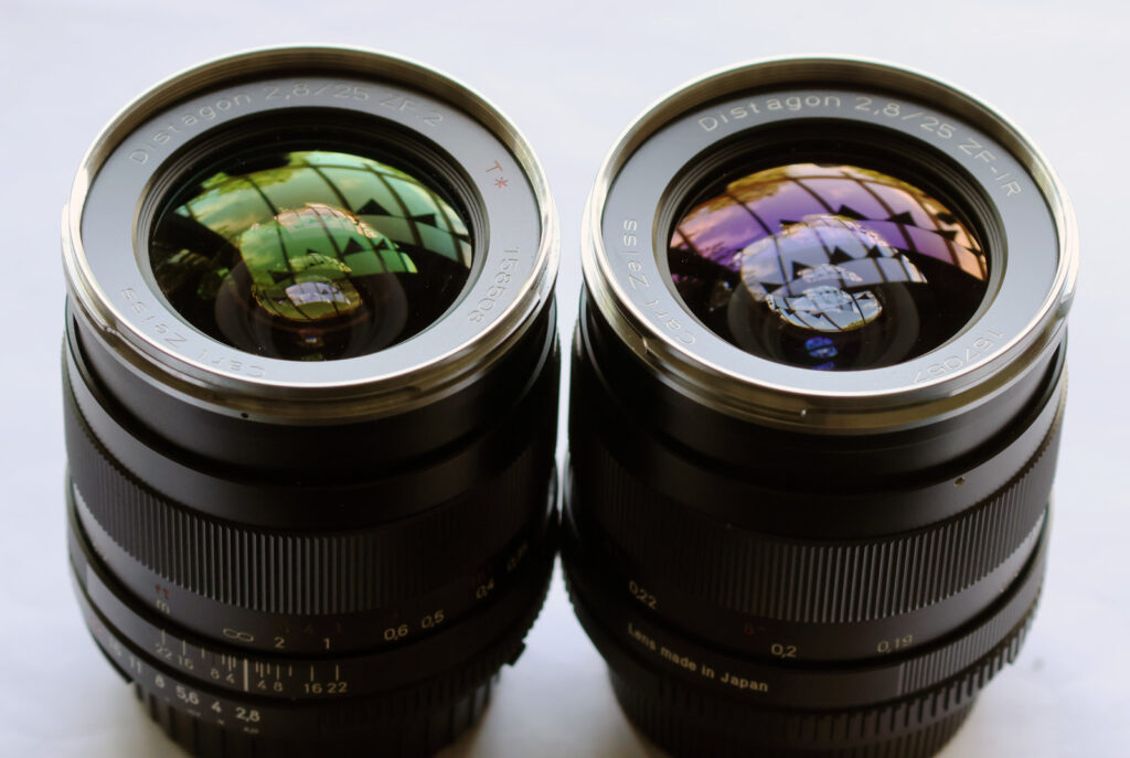
I’ll come to the transmission through the lenses in a minute, but to start with a visual comparison of the front elements of the 25mm ZF-IR and a normal version of the lens the 25mm ZF.2. This shows the reflection of sunlight through my kitchen window.

Coating colour from the Zeiss 25mm ZF.2 (left) and ZF-IR (right)

The coating on the front elements is very different between the two lenses as can be seen by their colour. Couple of things to note here. Ideally I would compare the ZF-IR with the ZF version, but I happened to have a ZF.2 copy of the lens. The ZF.2 came after the ZF but I would think the coatings would be very similar as the main difference was the addition of electrical contacts for providing aperture data. Note I have blurred the last 2 digits of the serial numbers on the lenses.

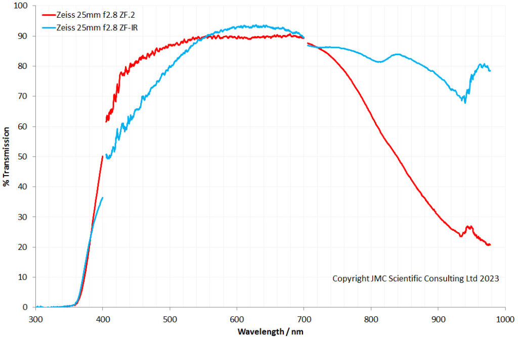
I measured the transmission through the 3 lenses I have (Zeiss 25mm f2.8 and 50mm f1.4 ZF-IR and 25mm f2.8 ZF.2) using my Ocean Insight spectrometers and a couple of light sources – xenon and halogen lamp. This allowed me to measure transmission from 300nm to 1000nm, although as I will explain with a couple of caveats.

First the comparison between the 25mm ZF-IR and ZF.2 lenses.

Zeiss 25mm ZF-IR and ZF.2 transmission comparison

The ZF-IR transmission is lower at the blue end of the spectrum than the ZF.2 but while the ZF.2 transmission drops sharply above 700nm the ZF-IR does not. This matches what I’d expect to see from the Zeiss product data sheets. My system sensitivity drops sharply above about 920nm, which is why the data gets very noisy up there, and I don’t think the drops and peaks at around 950nm are real features. The curves are shown in 3 sections as I used 3 setups to measure them. Overall though the ZF-IR certainly offers better IR transmission above 700nm.

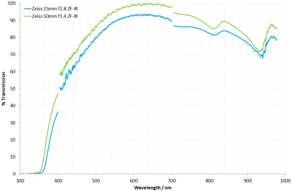
Now the Zeiss 50mm f1.5 ZF-IR and 25mm f2.8 ZF-IR.

Zeiss 25mm and 50mm ZF-IR transmission comparison

The Zeiss 25mm and 50mm ZF-IR have very similar shaped curves, which is what would be expected assuming they have the same coatings.

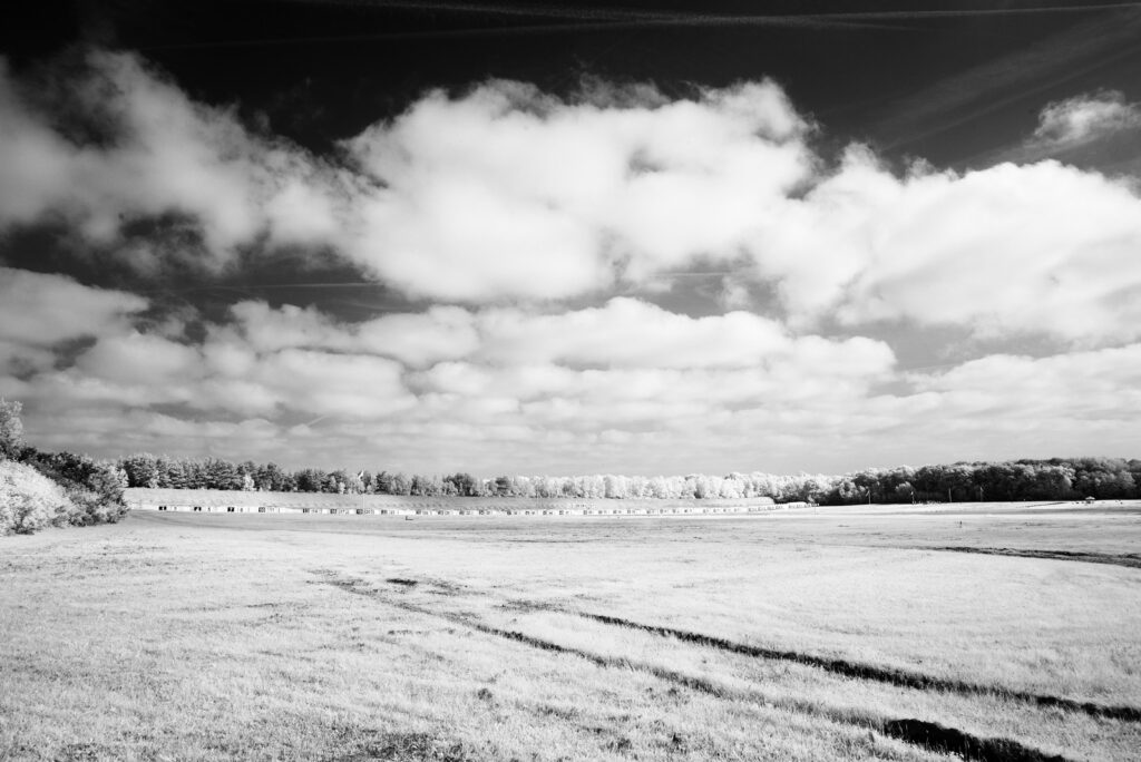
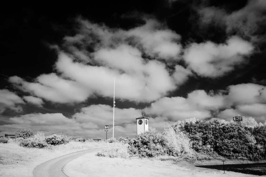
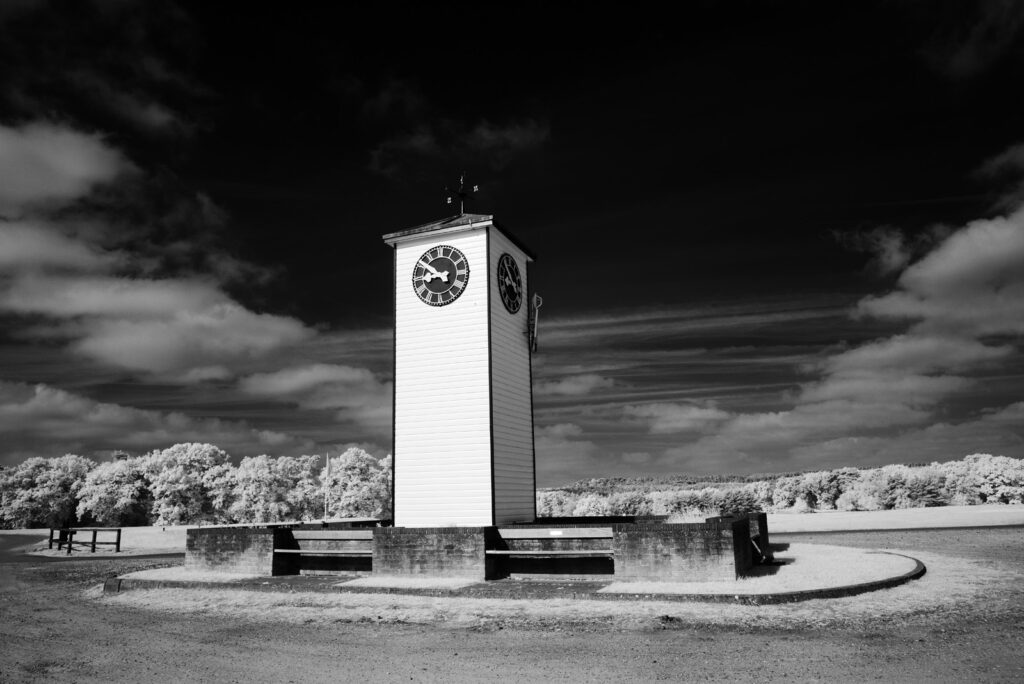
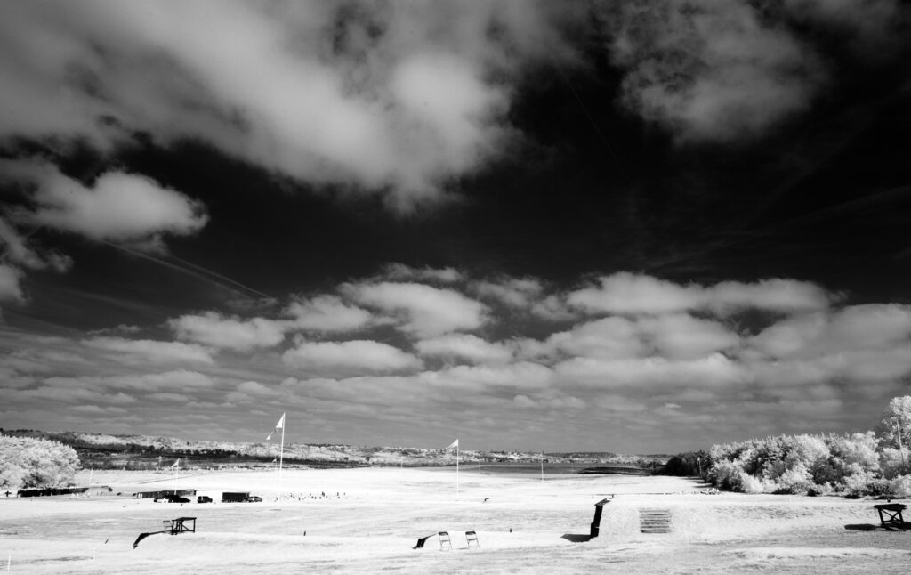
I did some quick landscape test shots with the 25mm f2.8 ZF-IR using my monochrome converted Nikon d800 camera from MaxMax and a Heliopan 780 IR filter, and these are show below.

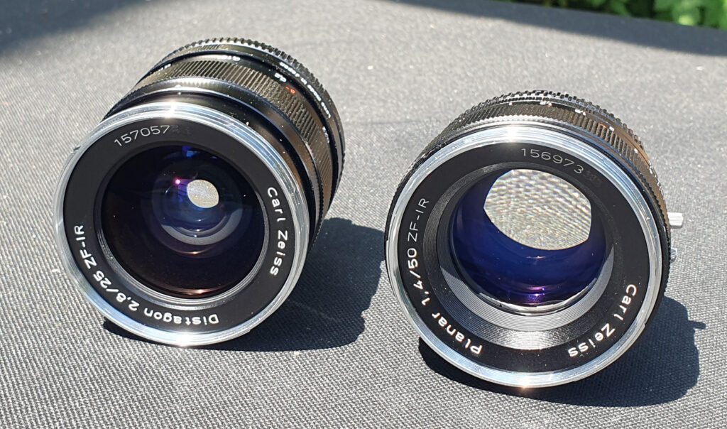
The lens certainly seems to live up to its reputation for not producing hotspots in the IR. I have heard that the 50mm ZF-IR is more prone to hotspots, although I have not been able to replicate that yet. To finish with, a not often seen photo of the 25mm and 50mm ZF-IR lenses together.

Zeiss 25mm and 50mm ZF-IR lenses

Overall, I’m very happy with the two Zeiss ZF-IR lenses and they will be a great addition to my non-visible light imaging capability. As always, thanks for reading and if you’d like to know more about my work, I can be reached here.

Microscopy – Hydrosilicon mitra diatom slide by S.H. Meakin

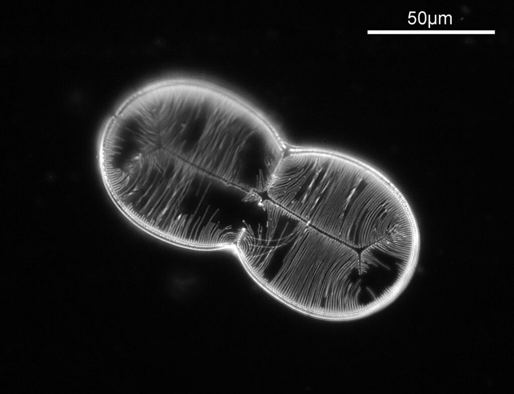
I have an unusual (and rather rare) diatom slide to share with you today – an example of Hydrosilicon mitra, prepared by S.H. Meakin. This was made in 1933, and is mounted in Hyrax (which will become important later). The images shared were taken on my modified Olympus BHB microscope, with a monochrome converted Nikon d800 camera. The images have been reduced in resolution for sharing.
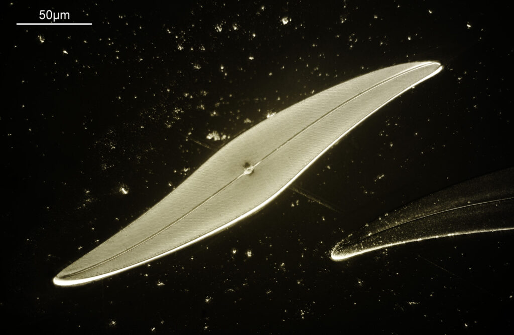
The first is a simple bright field image. This is a stack of 7 images and was done using 450nm filtered LED light. The objective was a 40x Olympus Dplan Apo UV (NA 0.85). Condenser was an Olympus Aplanat Achromat.

40x objective, bright field image

The sample is not flat, and dips towards one side. This means that stacking was necessary with the 40x objective (in fact I missed the focus on the top left of the diatom – ” ‘B-‘ must do better next time”). As can be seen there is some damage to the fine structure of the diatom, but it is still a very pretty specimen.

I wanted to see what this looked like with dark ground illumination, so I got out my Watson Holoscopic condenser (some info about that here) and used glycerine as the immersion fluid to attach it to the underside of the slide. The objective was a 20x Olympus Splan NA 0.46, and again 450nm light was used. No stacking this time, just a single image.

20x objective, dark ground image

I love the dark ground effect, but being a single image part of the diatom is out of focus due to it not being flat. I’ve not got my head around stacking dark ground images yet.

As a final image, I wanted to try something different. As mentioned above the mount is Hyrax, and this has pretty good UV transmission at 365nm. I wanted to try imaging with 365nm light (to potentially help improve resolution), and also use a different method of illumination – circular oblique light (COL), also known as annular illumination. To do this I used a 40x Olympus UVFL PL NA 1.3 silicone immersion objective in combination with the Watson Holoscopic condenser. This objective has an adjustable iris – wide open and the NA is bigger than that of the condenser and the image is bright field. Iris closed all the way down and the image becomes dark ground as the objective NA is now smaller than the condenser. In the middle ground COL can be produced, when the NA of the objective is close to that of the condenser. This gives a nice 3D effect to the image. Both the condenser and the objective were used with glycerine as the immersion fluid. The image below was a stack of 13 images, using 365nm LED light, and with a COL setup.

40x objective, COL illumination

COL illumination gives a more 3D effect to some of the features. But, and this is a big ‘but’, the resulting image was very noisy, and was a bit of a nightmare to stack. Not sure why it was so noisy, as I used ISO200 on the camera. I really like the end result though and will definitely try this technique again.

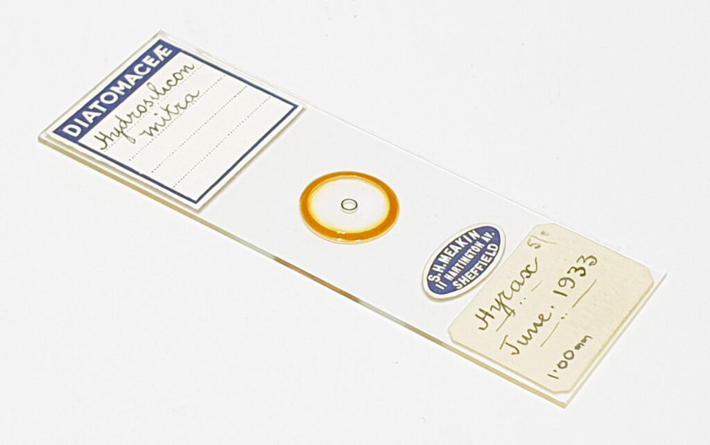
As always, here’s the slide itself as well.

Hydrosilicon mitra slide by S.H. Meakin

Not too bad for a slide made 90 years ago. The slide was bought on ebay for about £30 and there is a single example of the diatom on it. As always, thanks for reading, and if you’d like to know more about my work, I can be reached here.

Microscopy – cross polarized slide of acetate of strychnine

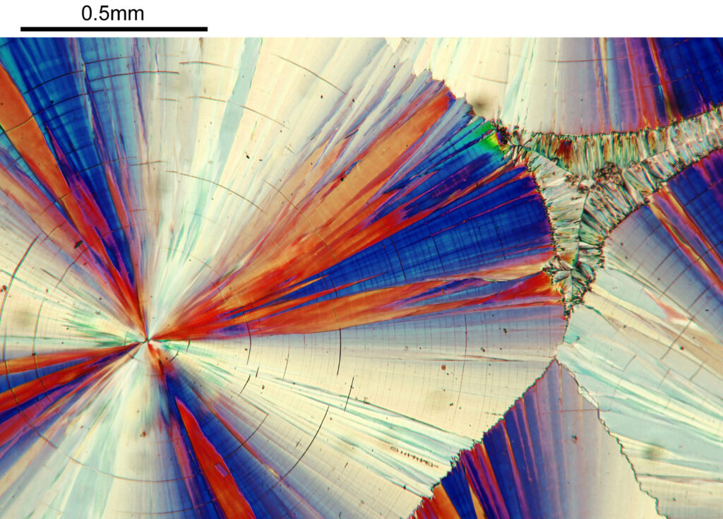
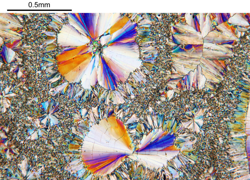
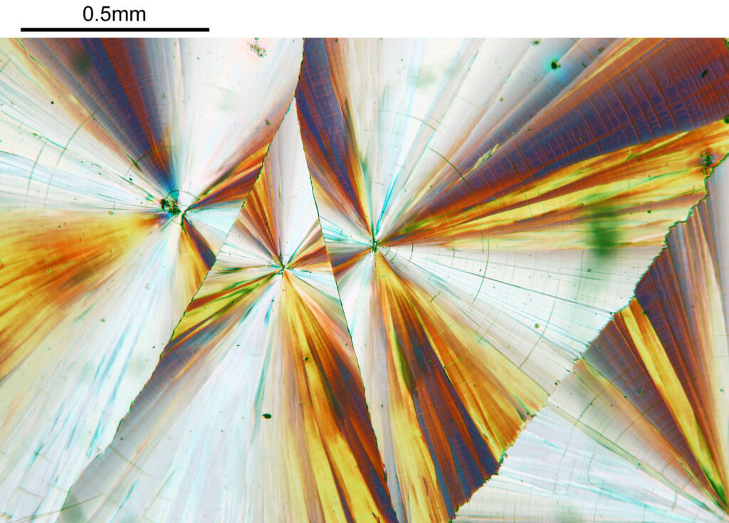
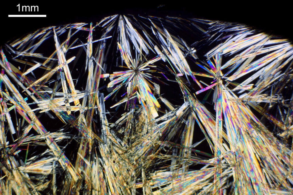
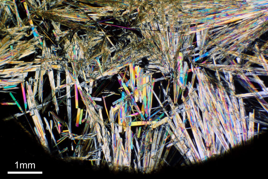
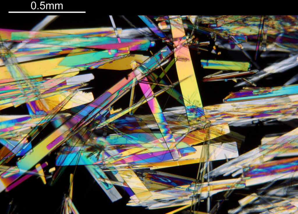
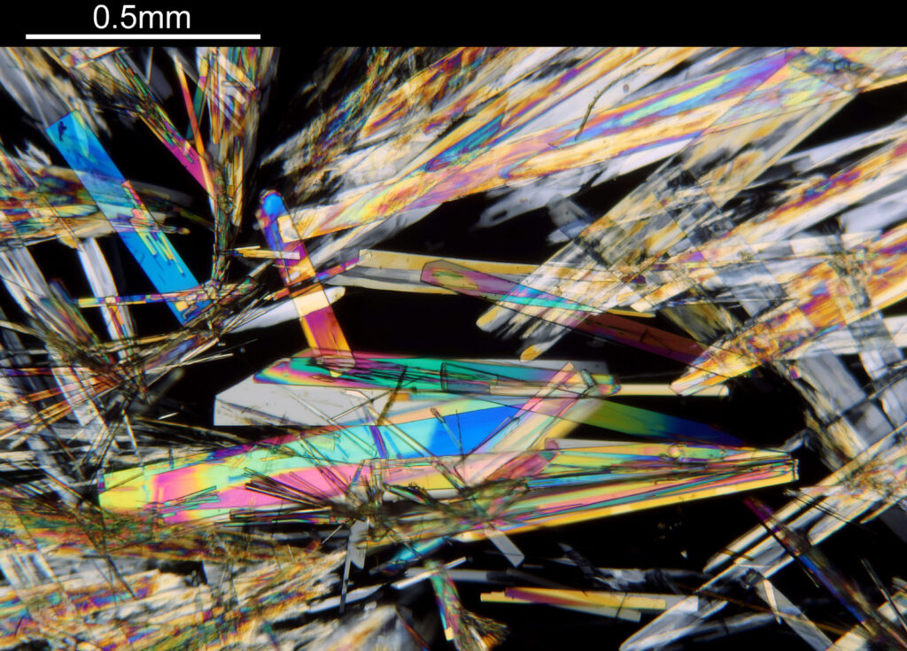
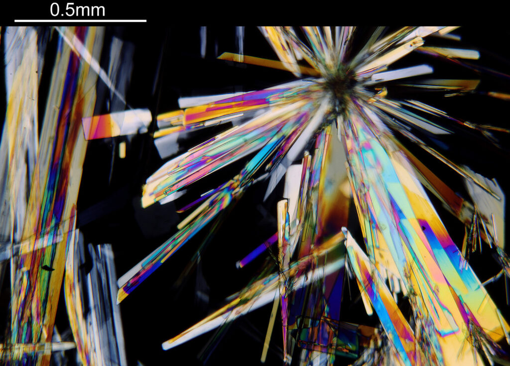
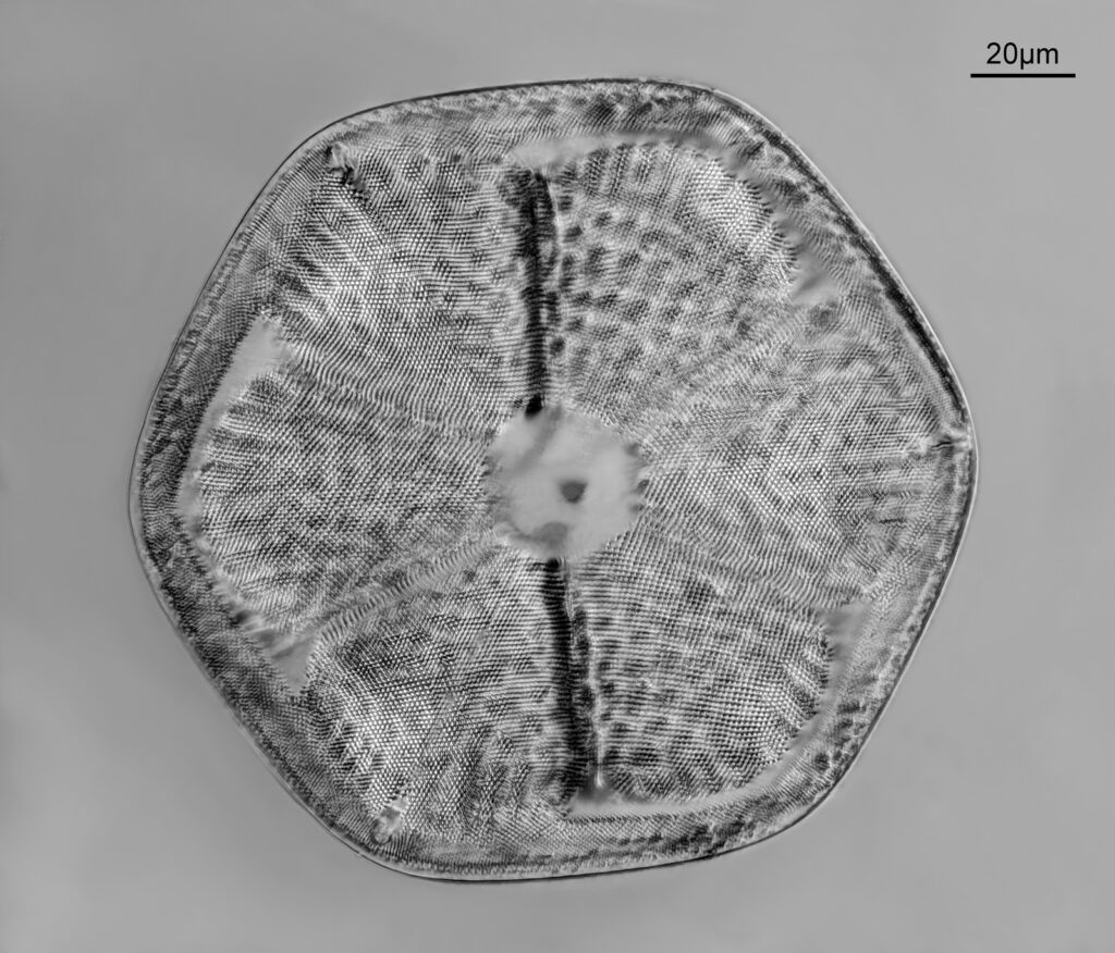
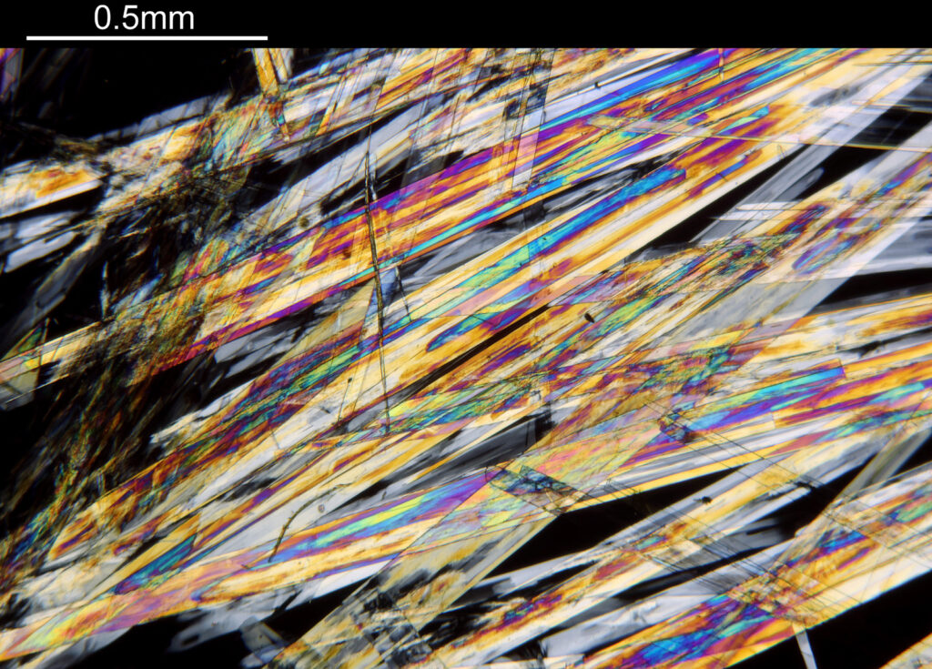
Today’s post shows some images of a slide of acetate of strychnine, made by John T Norman. Based on the available information I would date this to the late 1800s. Cross polarized lighting can be used to create wonderful coloured images of crystals, and I have used that technique here to image the crystals on the slide. Images taken using my modified Olympus BHB microscope and with a Canon Eos R7 camera. Objectives were a 1x Olympus Splan Fl and a 4x Zeiss Planapo. Images have been reduced in resolution for sharing.

1x objective
1x objective
4x objective
4x objective
4x objective
4x objective
4x objective

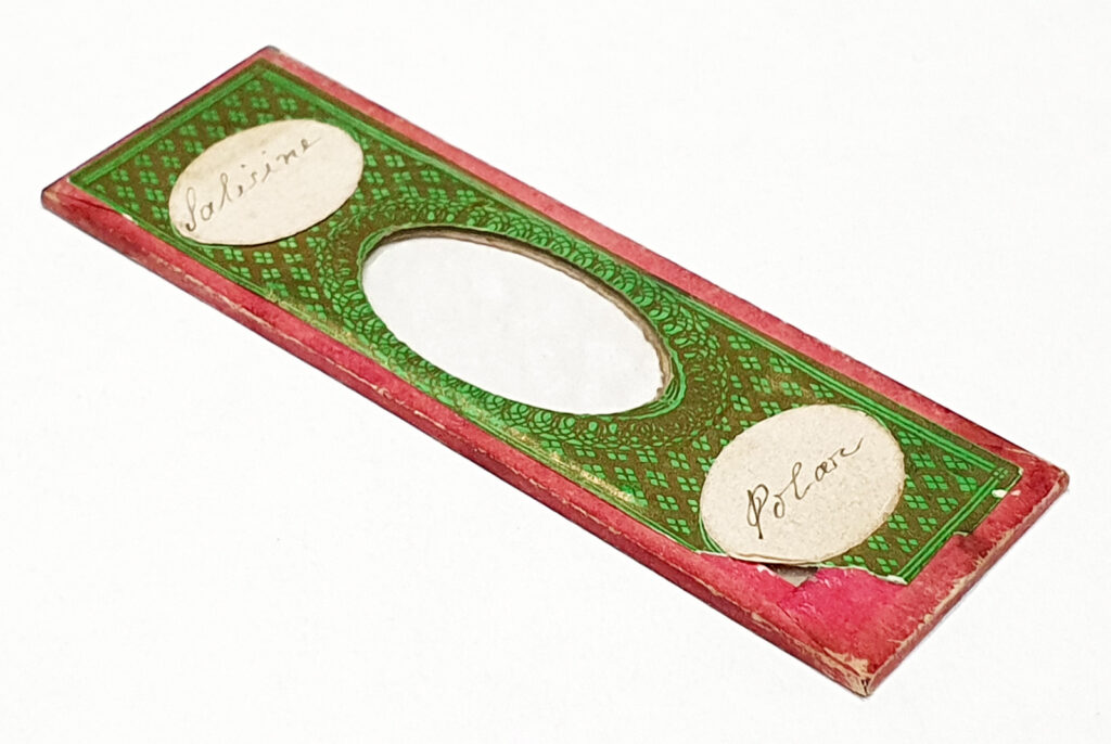
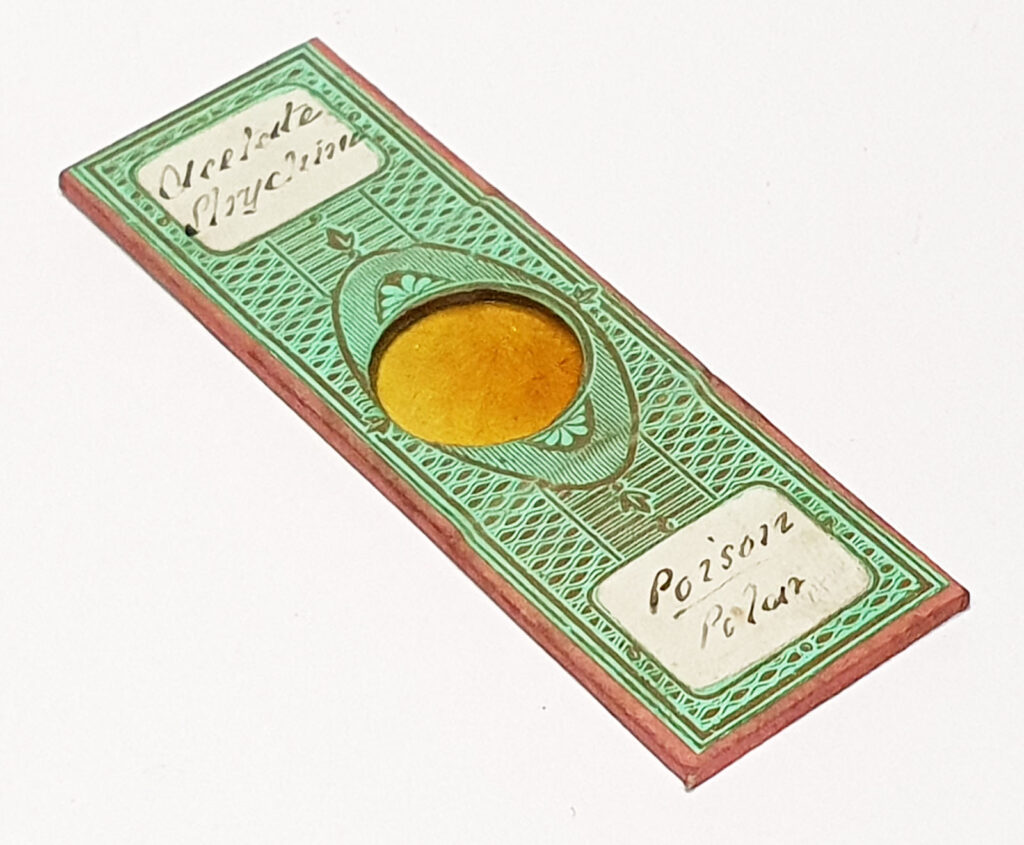
As always, I like to share an image of the slide itself, so here it is.

Acetate of strychnine slide by Norman

I find these cross polarized images of crystals absolutely fascinating, and I hope you do too. Thanks for reading, and if you’d like to know more about my work, I can be reached here.

Microscopy – Tasmanian rock with orange lichen

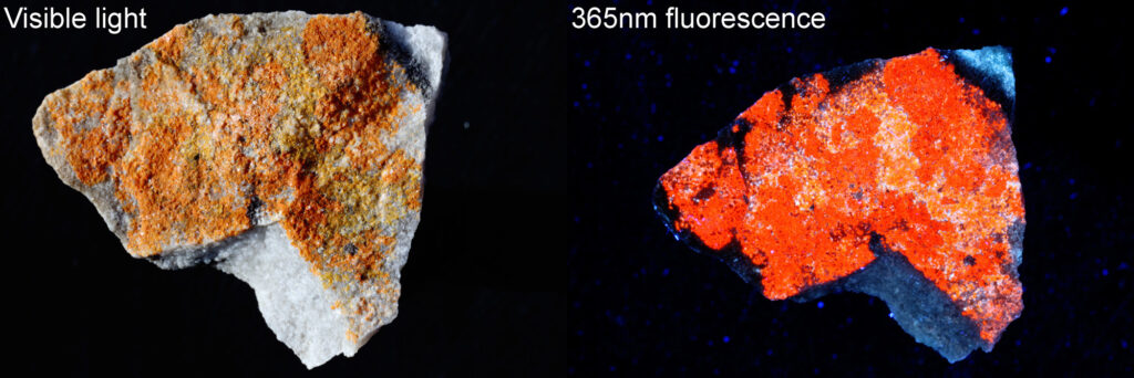
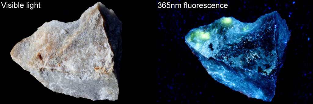
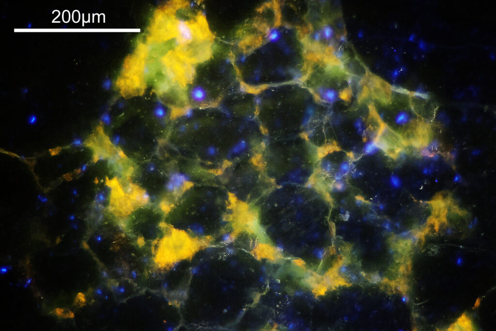
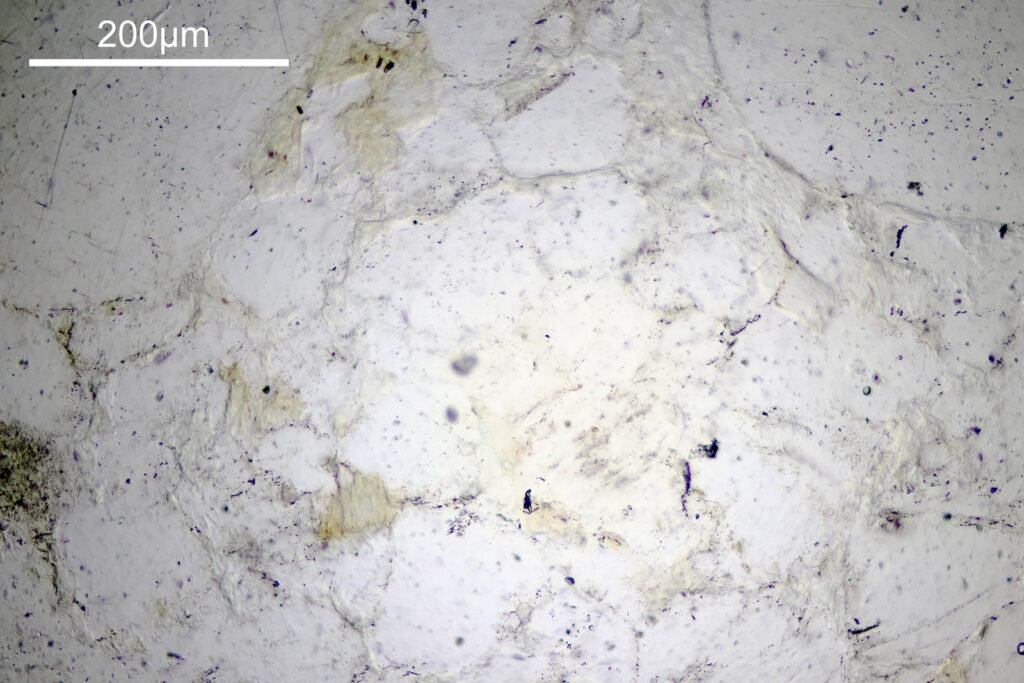
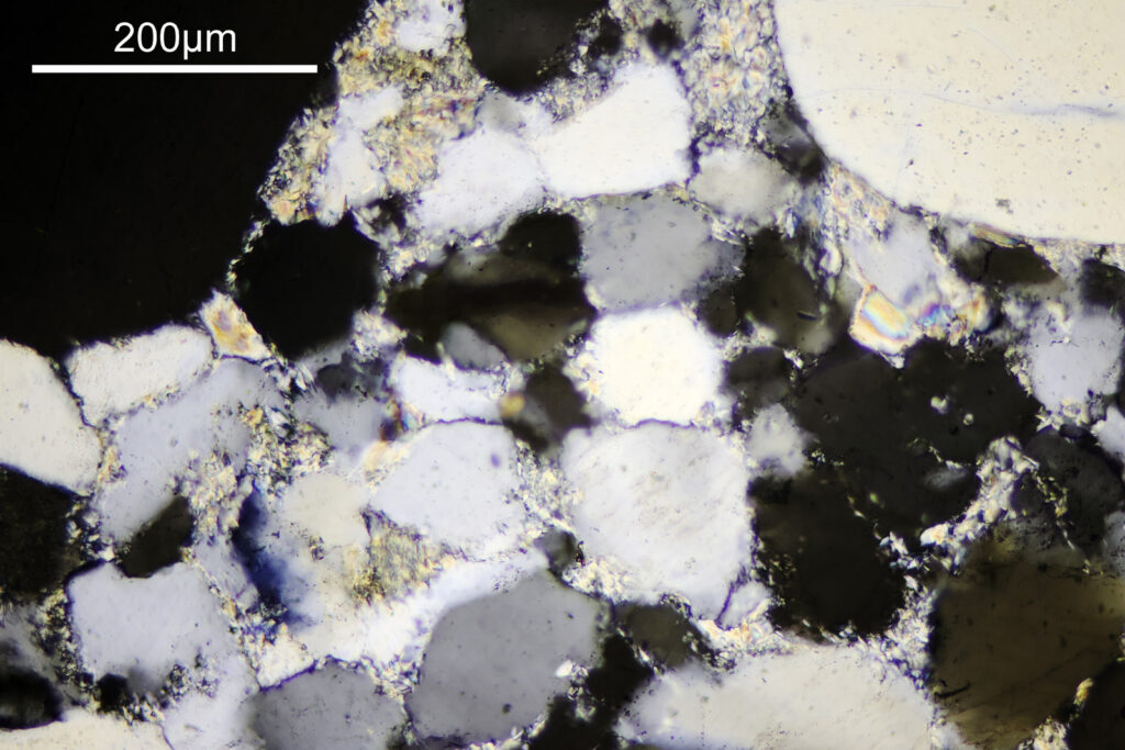
Earlier this year I picked up a rock with some orange lichen on it from a beach on the north west coast of Tasmania. I was interested to see how it looked under UV induced fluorescence and it did not disappoint (some initial fluorescence photos of it were shared here). A few weeks ago I came across an advert for someone who could make microscope slides of thin sections of rock (Dr Andrew Beard at Geology Hub) and I reached out to see if he would be able to make some thin sections of my Tasmanian rock sample so it could be viewed on the microscope. He was really helpful, and I sent him a few of my spare fused silica microscope slides (in case I wanted to try illuminating them with UV for fluorescence) and the rock sample and he made me a few slides to look at. Today’s post shared some initial images.

First a reminder, here’s the rock sample, front and back, in normal visible light and under UV induced fluorescence using 365nm light. It was about 3cm across and 1cm thick.

Front of the rock sample
Rear of the rock sample

The front surface had an orange lichen on it it which also fluoresced orange under illumination with 365nm light. The rear had a couple of areas (towards the top left of the image) in which the matrix of the rock looked to be fluorescing yellow under 356nm light. I asked Dr Beard to prepare a few slides of the rock showing 2 specific areas – the orange lichen and the yellow rock matrix fluorescence. For the microscopy images, I used my modified Olympus BHB microscope, an Olympus Abbe condenser, a 10x Olympus UVFL NA 0.4 objective, an Olympus 2.5x NFK photoeyepiece and a Canon EOS R7 camera (auto white balance). Single images, no stacking, and full frames are shown without cropping.

Imaging of different slides done as follows:

Fluorescence: 365nm LED torch, with ZWB2 filter on the front (probably 2mm). 3mm thick GG420 filter on top of the photoeyepiece.

Bright field: White LED light. 3mm thick GG420 filter on top of the photoeyepiece.

Cross polarized: White LED light. Linear polarizer on the field lens. Moxtek linear polarizer on top of the photoeyepiece. Polarizers rotated to extinction.

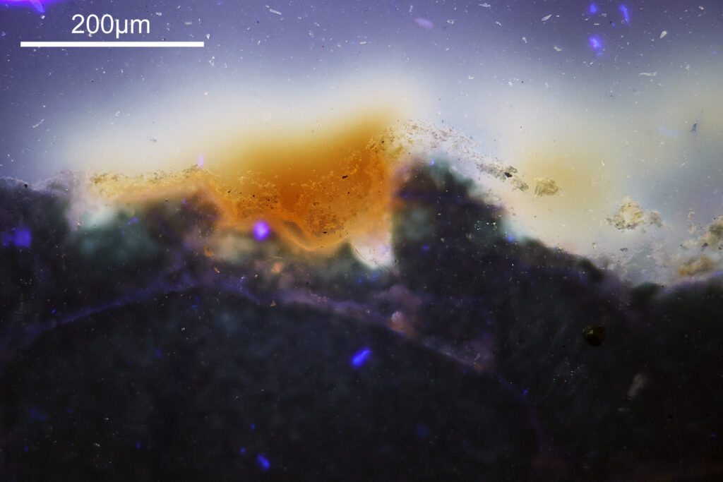
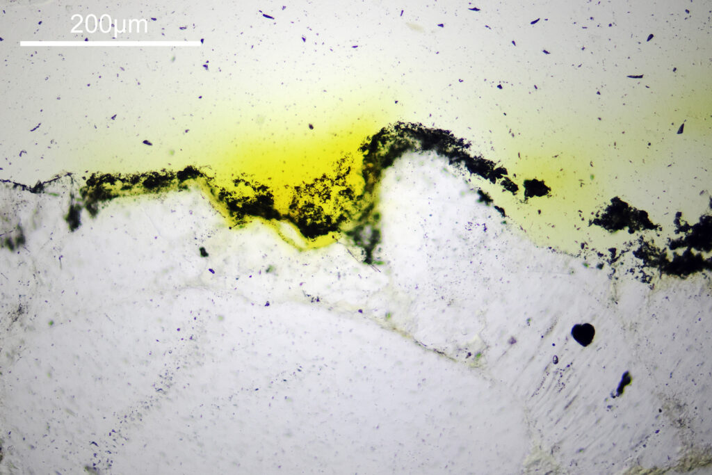
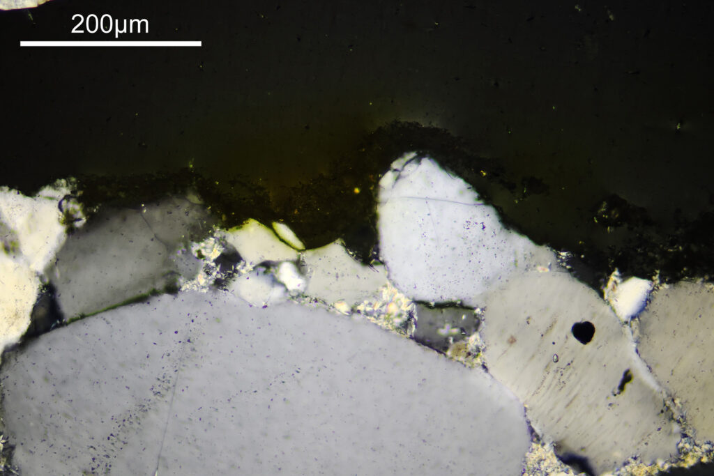
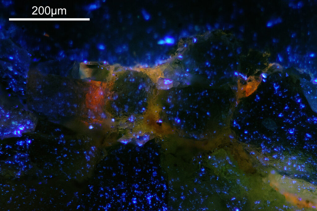
1st sample. A thin section (about 30µm) mounted in Petropoxy 154 resin and with a coverslip. The rock is at the bottom of the image, then a thin layer of lichen, and at the top of the image the mount. Shown as fluorescence, bright field, and cross polarized images.

Fluorescence image
Bright field
Cross polarized

What’s going on with these images? In the bright field image, the thin rock sample looks fairly transparent as does the mount. The lichen looks to be quite dark in the bright field image, with a sort of ‘powdery’ appearance. The orange colour from the lichen seems to have dispersed into the mount a bit. This is also obvious in the fluorescence image where now the lichen itself looks to be quite transparent but there is a strong orange fluorescence surrounding it. In the cross polarized image the lichen is no longer really obvious (although there is a slight orange/yellow look to parts of the surface of the rock), but the different crystals in the rock are now really visible.

Given the bleed of the orange from the lichen in the Petropoxy 154 mount, Dr Beard suggested he could try using a different mount for some other slides, and so that is what he did.

Next, a thicker sample (about 60µm) with no coverslip.

Fluorescence
Bright field
Cross polarized

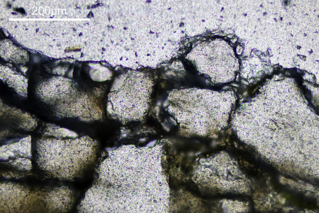
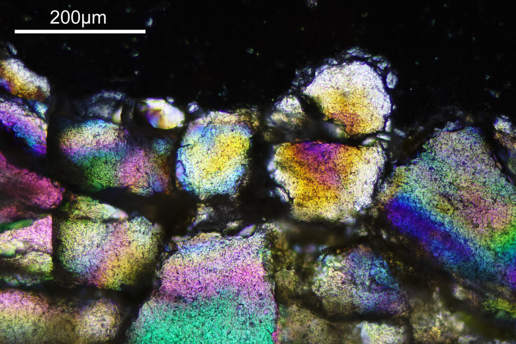
Again the rock is towards the bottom of the image. The top is now open space. This sample looks different to the first as it is thicker and has no coverslip. It is therefore more 3D in appearance. The lichen now shows as a general orange glow at the surface of the rock in the openings in between the individual grains. Nice colours in the cross polarized image but as these are thicker and not well defined slices, it doesn’t look the same as the thin section in the 1st set of images.

As a final set of images, these were also done with the newer mount, and as a thin section with a coverslip. This does not show the surface of the rock, but was an area of the matrix which had glowed yellow under 365nm light.

Fluorescence
Bright field
Cross polarized

There is a strong yellow fluorescence which looks to be coming from whatever is in between some of the individual grains which make up the rock. This was quite heterogeneous across the sample, and this was an area where the yellow fluorescence was particularly strong. The bright field image doesn’t really show us a lot, although there is a slight colouration on the areas which fluoresce. The cross polarized image shows the typical appearance of a thin section again. The areas which fluoresce yellow look different – not black/grey/white but more rainbow coloured. Presumably these are a different mineral to the grains. It reminds me a bit of the Yooperlite mineral I imaged here. I used fused silica for these slides as glass will block short wavelength UV. It is a bit overkill for 365nm light, but does allow me to try shorter wavelengths in the future if I want to.

Overall I am really happy with the samples prepared by Dr Beard at Geology Hub, and they enabled me to have a look at the Tasmanian rock sample under the microscope. Changing the mode of imaging (fluorescence, bright field and cross polarized) had a huge impact on the appearance of the sample. As always thanks for reading, and if you’d like to know more about my work, I can be reached here.

Microscopy – Diatom test slide by Meakin

It’s no secret that I like the old diatom microscope slides. They can be very well made and provide very photographable diatoms often for much lower prices than modern prepared slides. The one I’m sharing today was by Samuel Henry Meakin and was made in 1945. It is a diatom test slide with examples of a variety of different species. Images were taken on my modified Olympus BHB microscope, and using a range of different objectives (4x Zeiss Planapo, 10x Olympus UVFL, 20x Olympus Splan, and 60x Olympus Splan Apo). Lighting was from below via an Olympus Aplanat Achromat condenser (straight bright field and oblique), and was 450nm LED light. Photoeyepiece was an Olympus 2.5x NFK, and the camera a monochrome converted Nikon d800. No stacking was done for these. Images are shown at reduced resolution where the originals were >1600 pixels across (most of them).

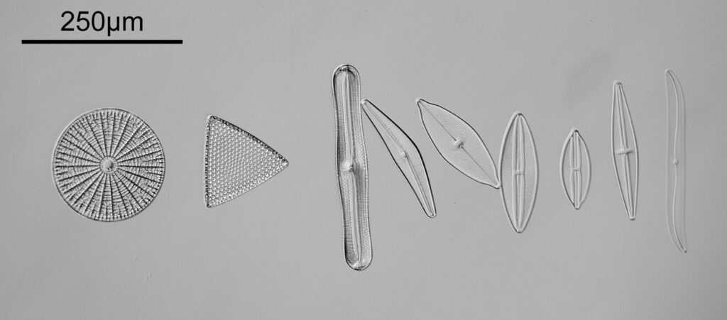
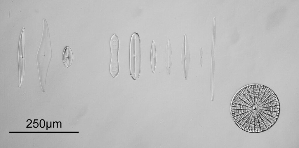
To start with, a low magnification image of the arrangement (4x objective).

4x bright field image showing the whole arrangement

The test diatoms are bounded at the left and right by large circular diatoms. Using 2 circular diatoms like this was often done by the slide maker Eduard Thum to help with locating the samples on the slide. They are arranged in a linear fashion, although there has been a little movement of some of them. The slide is shown below.

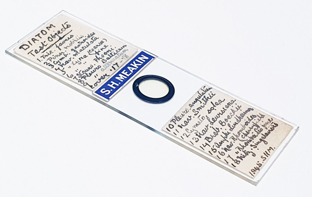
The Meakin test slide

What is great here is that Meakin has labelled the diatoms present (although not the circular ones on either end). They read as follows, going from left to right on the slide;

  1. Triceratium favus
  2. Pinnularia nobilis
  3. Cymbella gastroides
  4. Navicula maculata
  5. Navicula lyra coarse
  6. Navicula lyra fine
  7. Stauroneis phoenicenteron
  8. Pleurosigma balticum
  9. Pleurosigma attenuatum
  10. Pleurosigma angulatum
  11. Navicula smithii
  12. Cymatopleura solea
  13. Navicula lewisiana (also known as Frikea lewisiana)
  14. Brebissonia boekii
  15. Amphipleura lindheimeri
  16. Navicula rhomboides (Cherryfield)
  17. Navicula rhomboides fine
  18. Nitzschia singalensis

Some of these took some tracking down to get the details right as I struggled with the hand writing at times (especially for the less common ones). Overall the quality of the slide was very good, and the diatoms were intact. This is one reason why these types of test slides can be very nice – lots of intact, well prepared diatoms, great for imaging.

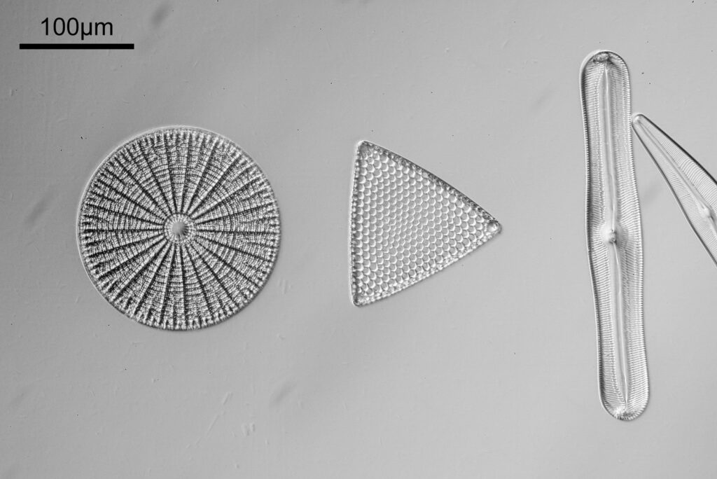
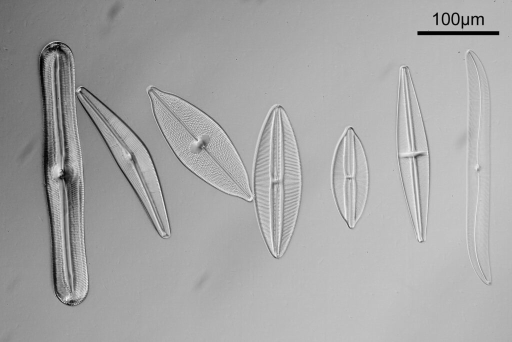
Going in closer, here are 2 images done with the 10x objective, oblique lighting.

10x objective, left side
10x objective, right side

Even closer now with the 20x objective (oblique lighting). There is some overlap between the images.

20x objective, image 1
20x objective, image 2
20x objective, image 3
20x objective, image 4

At this magnification, the details were starting to become obvious. So I went in closer to some of the diatoms using a 60x objective (oblique lighting).

60x objective
60x objective

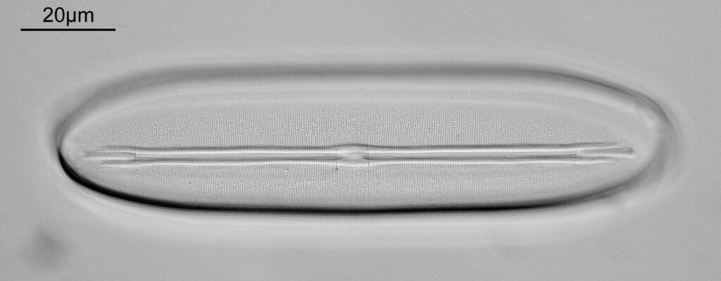
One in particular struck me as very interesting, and it was one which I had struggled with for the name – 13. Navicula lewisiana. I’d not seen one of these before, and here is how it looked with the 60x objective (oblique lighting).

60x objective, Navicula lewisiana

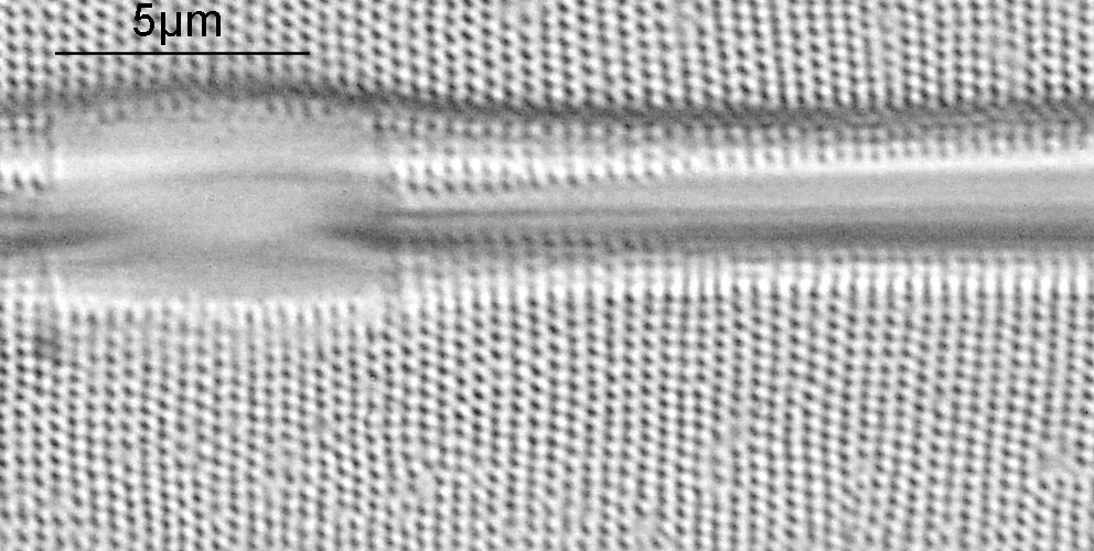
At this resolution the fine detail is lost. Below is a crop from the original. shown at original pixel resolution.

60x objective, Navicula lewisiana, cropped

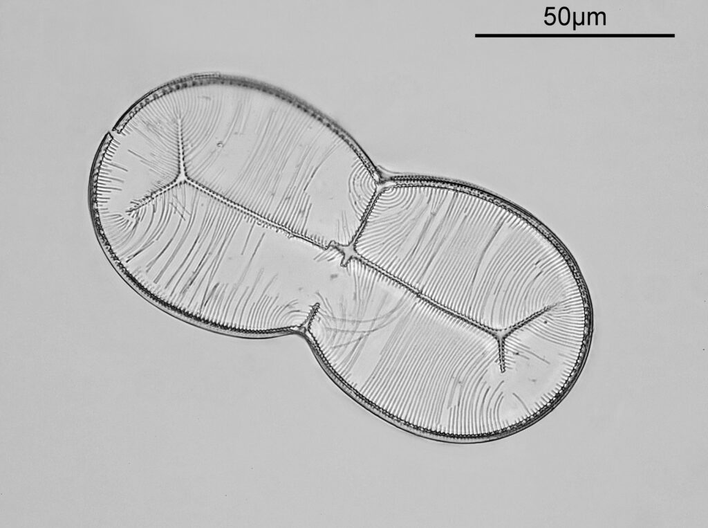
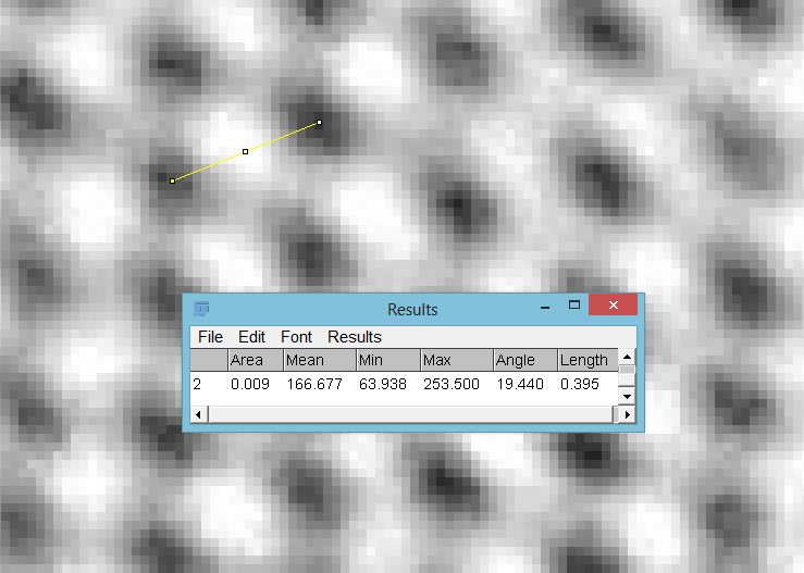
Putting this in ImageJ, the spacing between the poroids can measured, and it comes out to just under 400nm (shown as 0.395 in the image below).

ImageJ crop showing the poroids

As I mentioned, this was one I hadn’t seen before, but is one I shall come back to again to do more imaging on. Here’s some information on it on the Diatoms.org website. Also, it is in the excellent book “The diatoms”, by Round, Crawford and Mann, page 534, where is it mentioned that it is “A rarely recorded monotypic genus.”. Explains why I haven’t seen it before. While I am on the topic of books, I should also note that there is a bit of information about Meakin in “Microscopical mounts and mounters” by Bracegirdle (published by the Quekett Microscopical Club) which is a text I often refer to for getting background on mounters and slide makers.

As always, thanks for reading, and if you’d like to know more about my work, I can be reached here.
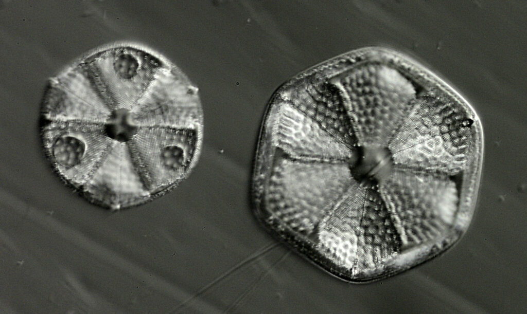
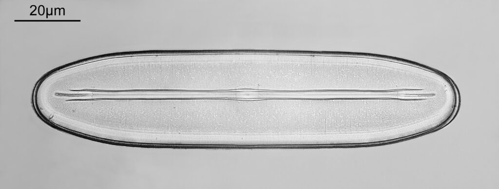
EDIT – I did return to the slide and did some more imaging of the Navicula lewisiana. Same objective (60x Splan Apo) but this time with 405nm light and stacking. In order to get a successful stack I reduced the extent to which the light was oblique, so this is essentially a bright field image.

60x objective, Navicula lewisiana, 405nm light, stacked

While there is now detail to the edge of the diatom, the image is a bit ‘flat’ – going away from oblique light and stacking makes it look less 3D to me. This one was tidied up more as well. I actually think I prefer the 450nm light image which wasn’t stacked, but this is more of a complete image of the diatom. Horses for courses as they say……

Microscopy – Dragonfly eye and polarized light

After my recent post about microscopy of a mammal eye, it got me on the lookout (sorry, couldn’t resist) for other eye microscope slides. Within a few days I had a cross section of Dragonfly eye on its way to me. This is a slide by Watson, and I was hoping I’d be able to do some cross polarized imaging on it. Today’s post shows the results of my work.

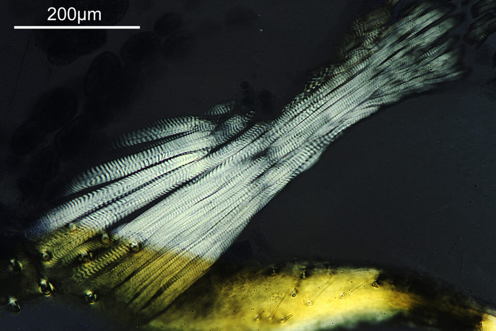
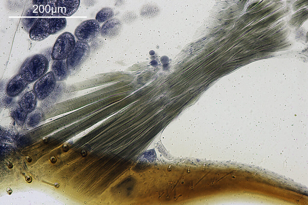
First a large field of view image showing the whole sample, using a 2x Olympus Splan Fl objective. Here are the images – cross polarized and plane polarized.

Whole sample, cross polarized, 2x objective
Whole sample, plane polarized, 2x objective

In the images above, the eye itself is towards the bottom of the slide, and the rest of the head towards the top. The eye shows some amazing structure from its compound arrangement. It looks like the very surface of it is most optically active. Within the head there are more regions of optical activity. I’ll come on to those later.

Something to note, the cross polarized images aren’t completely black in the background. I did not use Pol objectives, and some of them had fluorite in which may well be messing with the polarization a bit. Essentially I set the polarizer angles to give the nicest images and show the regions of optical activity. Photos were taken using a Canon Eos R7 camera just using auto white balance. Light source was a white LED light, and the microscope my modified Olympus BHB. Plane polarized imaged are essentially like non-polarized ones in appearance. It was easier to do that than keep removing the polarizer from the photoeyepiece.

Going in a bit closer now. First on the surface of the eye, with a 4x Zeiss Planapo objective, and a 10x Olympus UVFL objective, and again, cross polarized and plane polarized.

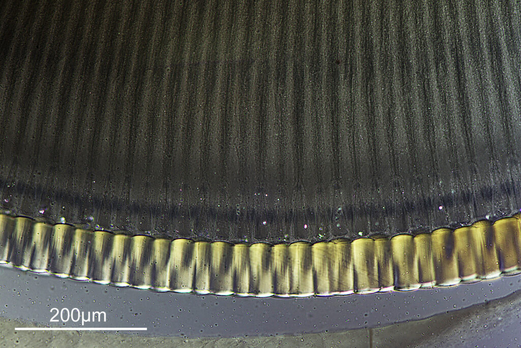
Eye, cross polarized, 4x objective
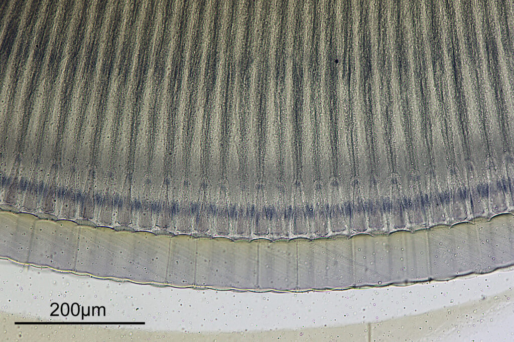
Eye, plane polarized, 4x objective
Eye, cross polarized, 10x objective
Eye, plane polarized, 10x objective

Cross polarization shows the nice optical activity in the surface of the compound eye.

Now going into the head itself let’s a have a look there, again with the 4x and 10x objectives.

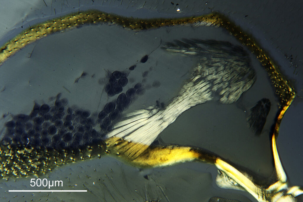
Inside the head, cross polarized, 4x objective
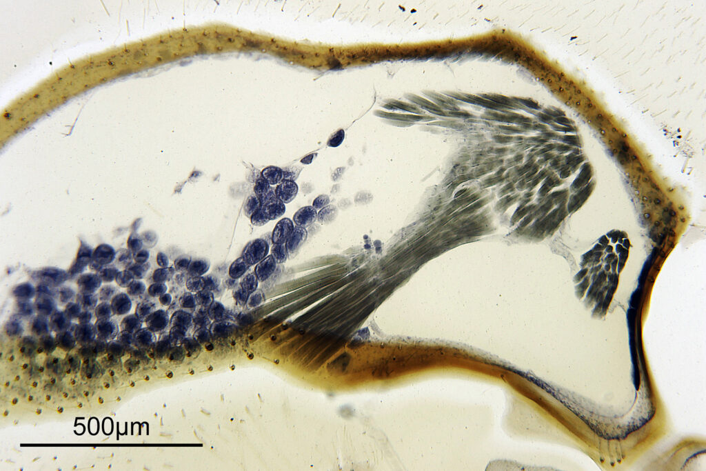
Inside the head, plane polarized, 4x objective

Moving in closer to the bundle of fibers in the middle of the image we get these.

Bundle of fibers, cross polarized, 10x objective
Bundle of fibers, plane polarized, 10x objective

I’m guessing these are a bundle of muscle fibers used to move the eye around. They are very optically active under cross polarized imaging.

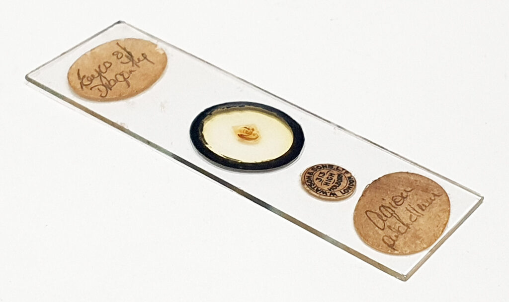
Before I wrap this up, here’s the slide itself (a Watson one).

Dragonfly eye slide by Watson

I was hoping that this slide would allow me to image it in cross polarized lighting (unlike the mammal eye one which had an optically active mount) and it did not disappoint. What we capture in an image depends strongly on how we image the subject, and changing things like polarization of the light can have a huge impact on what becomes emphasized in the final photograph. These old slides continue to amaze me, and I look forward to sharing more of them in the future. As always, thanks for reading, and if you’d like to know more about my work I can be reached here.
Microscopy – eye cross section

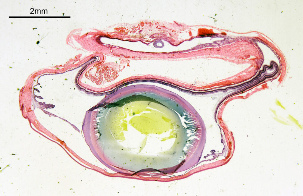
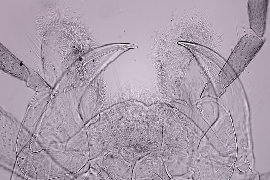
Continuing with my microscopy journey, I thought I would try imaging an eye cross section to get a better understanding of the visual organ. After having missed out on a couple of old slides of eye sections, I ended up getting one from a seller on eBay (here described as Eye Entire VS). I’m fairly sure this a ‘mammal’ eye, not specifically a ‘human’ eye, but it’s interesting nevertheless. Here’s what it looked like.

First an image of the whole specimen with a 1x objective.

Eye cross section, 1x objective

The eye itself is towards the bottom of the image (if that wasn’t obvious). The lens is the oval feature which looks purple/green/yellow. The eyeball itself is squashed here so is no longer spherical. I had hoped to look at the sample with cross polarized light to look at the construction of the lens itself, but the slide mount is crystalline and so this wasn’t possible. Note to self, keep looking for an older sample in case that doesn’t have a crystalline mount.

How about if I look at the sample with a 40x Olympus Dplan Apo UV objective, what can be seen? Images using this higher magnification are given below.

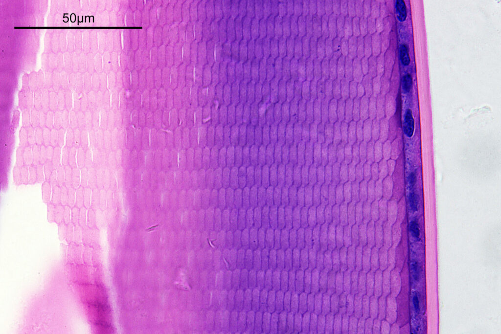
Edge of lens, 40x objective
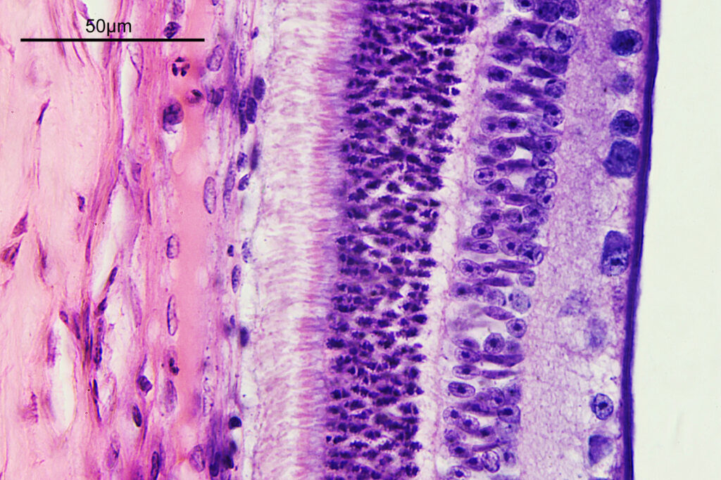
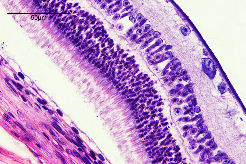
The retina region, 40x objective

There are some beautiful features in the sample of the slide. What are we looking at though? In the first of the three images above it is showing the lens of the eye and you can see the cross section through the lens fibers. I had hoped to look at this using cross polarised light, but as mentioned this wasn’t possible due to the mount used to make it.

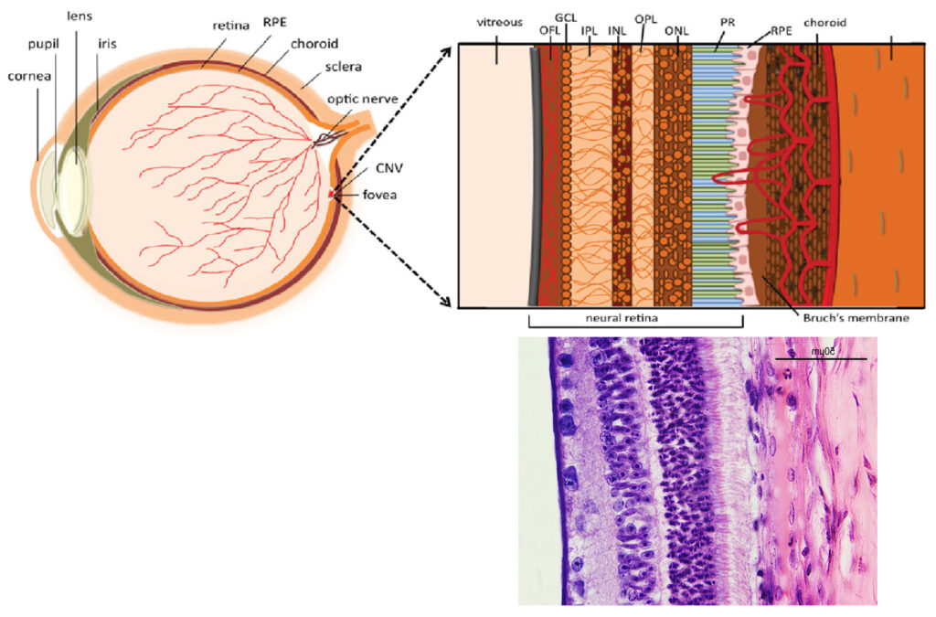
The second and third images are the tissue at the rear of the eye – the retina region. I found a nice paper which shows the different layers present (The Role of Photodynamic Therapy in Non-malignant and Malignant Eye Disorders, by Nowak-Sliwinska et al.). I took one of my images, flipped it horizontally and put it below their schematic.

Schematic drawing of a cross-section of the human eye, and an enlarged schematic cross-section of the macula with the components of the neovascular membrane. OPL: Outer Plexiform Layer; OFL: Optic Fiber Layer; ONT: Outer Nuclear Layer; GCL: Ganglion Cell Layer; PR: photoreceptors (rods and cones); RPE: Retinal Pigment Epithelium; IPL: Inner Plexiform Layer; NFL: Nerve Fiber Layer; ILM: Integral Limiting Membrane. Modified from The Role of Photodynamic Therapy in Non-malignant and Malignant Eye Disorders

Although slightly different thicknesses, the schematic lines up quite well with my image. It’s interesting to see the rods and cones in the retina, and it makes me realise how complex it is back there.

I did return later to the slide and looked at it with my 60x Olympus Splan Apo NA 1.4 objective, and my monochrome Nikon d800. This was done with white LED light and is a composite of 2 images stitched together. It has been hugely reduced in resolution for sharing here – this one is 1600×517 pixels, while the original was 14540×4701 pixels.

The image above shows the tissue from the rear of the eye (the retina) on the left, the remains of the vitreous humor in the middle of the image, and actually part of the eyeball lens itself on the right (the features you can see in there are the lens fibers). I had hoped to get more detail on the rods and cones, but wasn’t able to do that here.

Overall it seems to be a nice little slide, and one I will try and come back to with higher magnification to look more at the rods and cones. As always, thanks for reading, and if you’d like to know more about my work I can be reached here.
Microscopy – Imaging coal with cross polarization

A bit of a change from my normal microscopy work today. For one thing it’s colour images. Another is the subject – a thin section of coal. Also the technique used – cross polarized microscopy. Let’s get in to it.

The sample is a slide by Charles Morgan Topping and likely dates to around 1860. I’ll show a picture of the slide at the end of the post. It has a thin section of coal on it and is described as “Trans sect[ion] of coal. Warwickshire”. The section of coal is about 1cm across and mounted under a coverslip. First a normal bright field image (using a 1x Olympus Splan FL NA 0.04 objective).

Coal section imaged in bright field

And now the same sample imaged using cross polarized light.

Coal imaged under cross polarized conditions

Note that to get the whole sample in the field of view, I had to remove some of the extension tubes from between the photoeyepiece and the camera. While the increases the field of view it does mean that the edges of the image (which wouldn’t normally be seen in the standard setup) are included. These parts of the images above have some pretty severe aberrations present which is why the edges are nowhere near as sharp as the middle of the image.

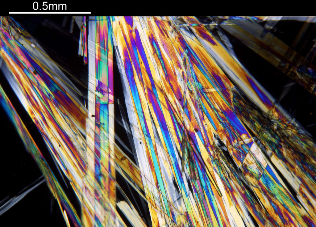
The cross polarized imaging sends the background very dark, and now crystalline material which is present becomes very colourful as it rotates the polarized light passing through it. At this scale, this is especially visible in the white band towards the left of the coal sample. This is where my knowledge of coal is getting a bit stretched. I think the dark bands running almost vertically in the images are growth rings from the original plant material – think tree rings.

Going in closer with a different objective now (a 2x Olympus Splan FL NA 0.08). All the images from now on will be cross polarized.

2x objective image
2x objective image

For the observant amongst you, you will have noticed that these images look more than 2x magnified compared to the images with the 1x objective. The extension tubes were put back in between the photoeyepiece and camera, having the effect of increasing the magnification (and getting rid of the aberrations at the end of the field of view). The dark bands running from top to bottom are now more clearly visible, and there are small ‘dots’ present as well in between the bands, which are coloured. The strongly coloured area towards the left of the image is the crystalline region shown towards to the left of the 1x images. This is very crystalline as can be seen from the colours present in the image.

Going in even further with a 10x Olympus UVFL NA 0.4 objective, the ‘dots’ become more visible.

10x objective image
10x objective image
10x objective image
10x objective images
10x objective image
10x objective image
10x objective image
10x objective image
10x objective image

At this scale the ‘dots’ become little stained glass windows, taking on a kaleidoscope of colours. As I said before I think these areas were originally cells in the plant matter when it was alive. These have then become filled with crystalline mineral during the fossilization process. The slide says ‘Warwickshire’ on it, and if so the coal fields of Warwickshire date to 300-350 million years ago. If these features were originally cells in the plant, then they are 300-350 million year old cells.

Some additional information. Here’s the slide.

Charles Topping slide, trans section of coal, Warwickshire

I’ve been told this was made by Charles Morgan Topping and dates to around 1860. There’s more on Topping here.

Also, the two low magnification objectives – Olympus 1x and 2x SPlan Fl.

Olympus 1x and 2x SPlan Fl objectives

As always, thanks for reading, and if you’d like to know more about this or other aspects of my work I can be reached here.
Microscopy – 4 historical diatom slides

I’ve had a bit of a catch up this weekend and looked at some slides that have arrived recently. They are both pretty and interesting (for different reasons), so I thought I would post them here. All have been reduced in size for sharing.
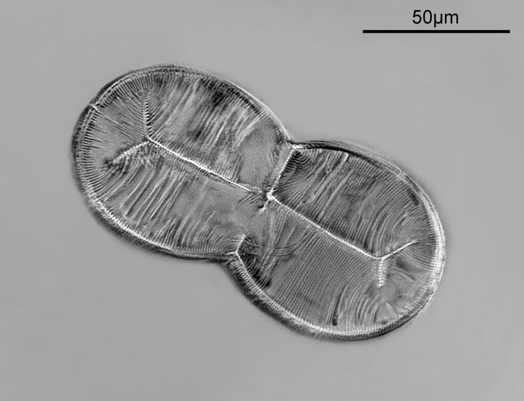
First is a Pinnularia slide by Arthur Cole.
Pinnularia slide by Arthur Cole
Pinnularia slide

There was a single example of the diatom on this slide. The mount was amazingly clear and needed very little cleaning up. Imaging was simple bright field, using 450nm light. Date for this is likely the late 1800s.
Next we have a Triceratium scitulum slide by Thomas Russell of London.

Triceratium scitulum slide by Russell
Triceratium scitulum slide

A nice arrangement of 4 diatoms. Again the mount was very clear and needed very little cleaning up. Imaging was brightfield with 450nm light. Likely date for this one, late 1800s.

I returned to this slide the next day and took a picture of one of the diatoms using the Watson Holoscopic condenser to give a dark ground image.

Triceratium scitulum slide by Russell using a Watson holoscopic condenser

Using the Holoscopic condenser has brought out the dot features present within the polygonal structures which were barely visible in the bright field image. The ‘dots’ look to be about 500nm across.

Now an arrangement of Actinocyclus by Eduard Thum, Leipzig.

Actinocyclus arrangement by Eduard Thum
Actinocyclus slide

A typical Thum arrangement using two large circular diatoms to mark where the arrangement is. Imaging was oblique brightfield with 450nm light. Likely date for this one, again late 1800s.

Last but not least is a Bacteriastum furcatum slide by Watson.

Bacteriastrum furcatum slide by Watson
Bacteriastrum furcatum slide

Imaged using 450nm light and a Watson Holoscopic condenser (discussed here) to give the dark ground image. Single images, no stacking.

There are always lots of these interesting old diatom slides available on places like Ebay and in my experience they offer great value for money for those wanting to image slides, so don’t discount them because they are old. As always, thanks for reading and if you’d like to know more about this or other aspects of my work, I can be reached here.