
As a photographer who spends a lot of time working outside of the visible spectrum I regularly use filters on my lenses or inside my camera to isolate the wavelengths of light I’m interested in seeing.
However filter choice can be far from straightforward, especially when imaging in the UV region. Today, I’ll give a quick example of why this can be a problem. First though a question – when is a filter not a filter? Take a red filter, which is often used in black and white photography to darker skies and lighten foliage. What is it doing to the light? What a dumb question, it’s letting red light through. Well, yes, it is, but then a simple clear glass filter would let red light through. With filters it’s not so much about what they are letting through (although that is obviously important), it’s about what they don’t let through. A red filter is red because it blocks light that isn’t red – it lets red through while blocking other wavelengths. When imaging in the UV region, this blocking becomes very important, because cameras are relatively insensitive in the UV region compared to the visible and IR regions. If the blocking on the lens isn’t up to scratch hen wavelengths you’re not interested in can make it through to the sensor and contaminate the image.
There are two main types of filters that photographers use – ionic filters such as Schott UG11 or Hoya U-340 which filter the light using the bulk properties of the glass itself, and dichroic filters which have a thin coating on one or both surfaces the glass which provides the filtering. Dichroic filters can just be on plain, colourless glass or they can be applied to an ionic filter, so the filtration is provided by the coating in addition to the bulk of the glass. An example of a dichroic filter in widespread use for UV photography is the Baader Venus U (commonly known as the Baader U).
Dichroic filters can be tailored to allow for very sharp cutoffs on the filters, and also high transmission, while ionic filters tend to have much smoother transitions. On the face of it, dichroic filter would seem to be perfect, for the UV photographer, offering high transmission and in theory excellent blocking of out of band wavelengths.
But there is a bit of an issue with dichroic filters which can be a problem if not considered. That is the effect that the angle between the incoming light and the filter has on its transmission properties.
Let me explain. I shall start with an example of an ionic glass UV filter – the LaLa U made by UVIRoptics. The LaLa U is an ionic filter stack which lets UV through while blocking visible and IR. Here’s what the transmission through the filter looks like at two angles – light incoming at 90 degrees to the filter, and at approximately 45 degrees.
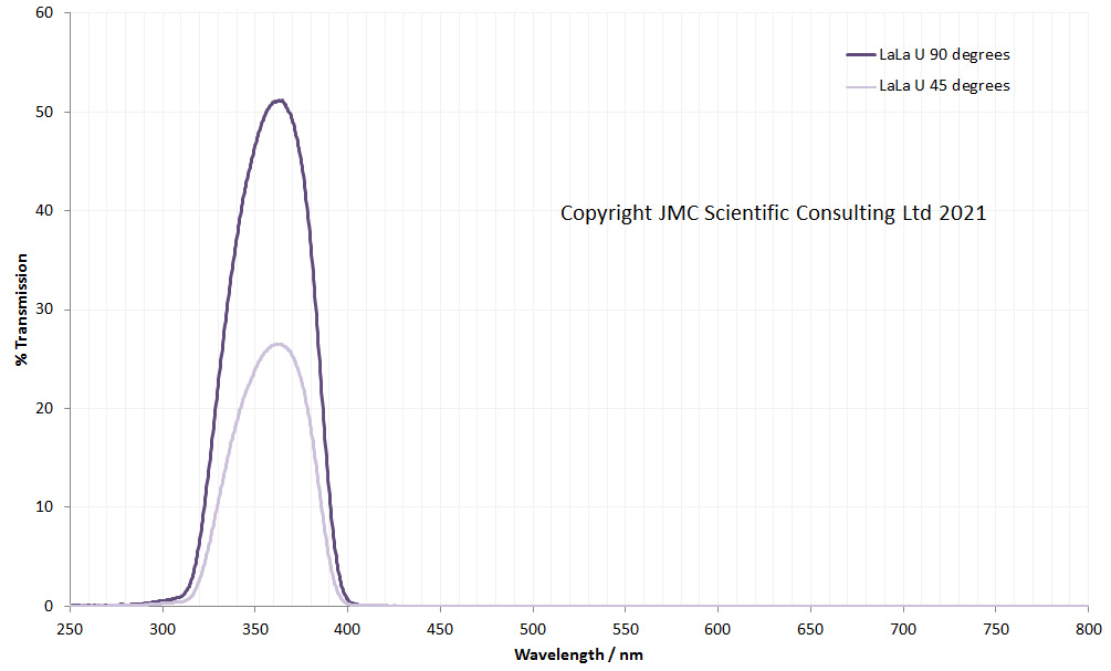
Transmission was measured using an Ocean Insight FX spectrometer and light source. Tilting the filter to 45 degrees drops the transmission (as the light is going through a lot more glass), but the shape of the transmission peak doesn’t change. If the graph is replotted to look for leaks, I get the following.
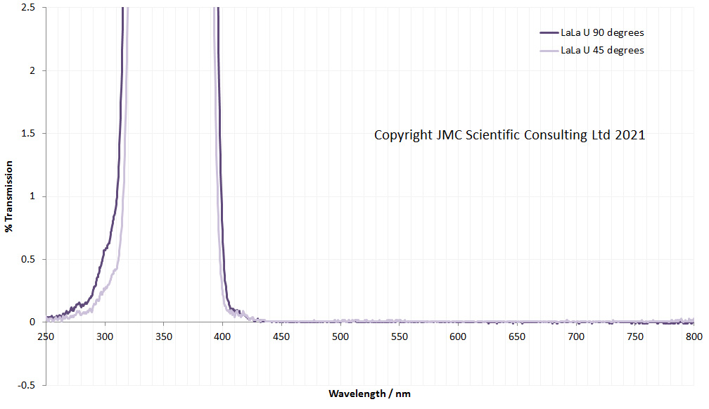
As expected, the LaLa U has good blocking in the visible and IR regions, and tilting it does not make a difference.
Now, what happens when we look at the dichroic Baader U filter in the same way? First graph, full scale, second graph magnification to look for leaks.
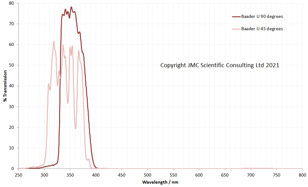
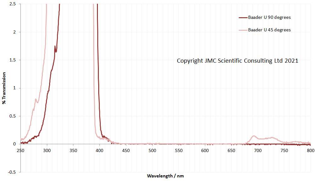
The Baader U behaves very differently as it is tilted. Unlike the ionic LaLa U filter, the Baader U transmission spectra shifts to a shorter wavelength when the light is at 45 degrees to the surface of the filter. In addition the UV transmission profile is much more jagged in shape. Also, and even more concerning it is now letting in light above 680nm, and while 0.2% transmission may not seem like a lot, this can be an issue for UV imaging.
Some dichroic filters have even tighter transmission regions than the Baader U. Examples of these include Edmund Optics and Thorlabs 10nm bandpass filters. These both claim to have high blocking of out of band wavelengths, while at the same time giving high throughput in the region of interest. I use these for filtering light sources and also for imaging in front of camera lenses, although they are normally used more for filtering light sources than imaging.
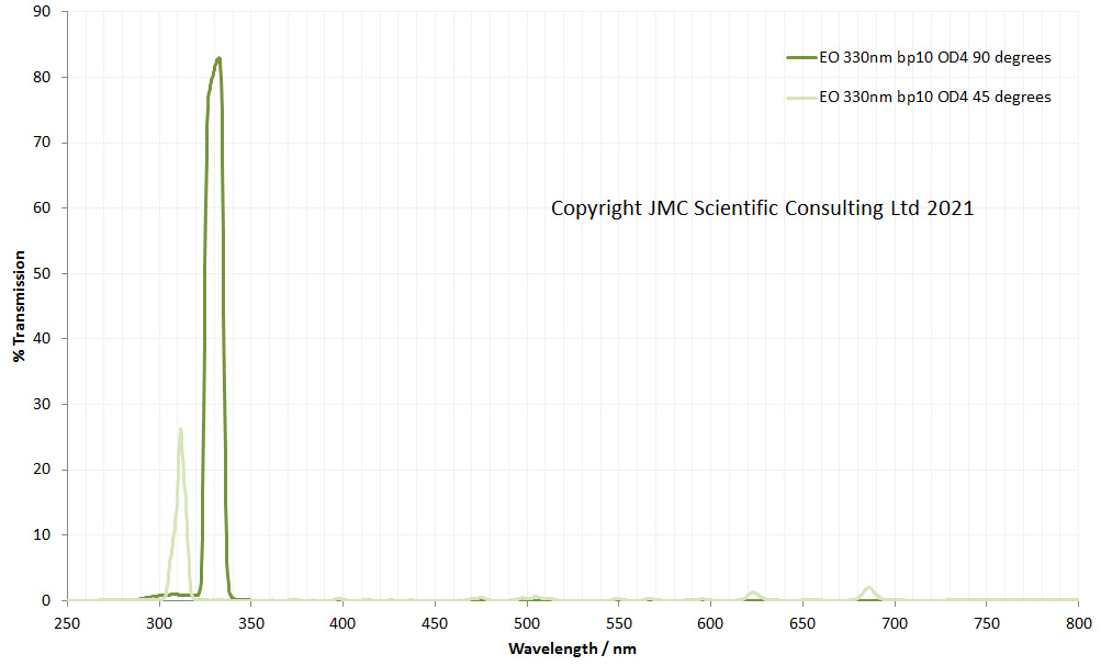
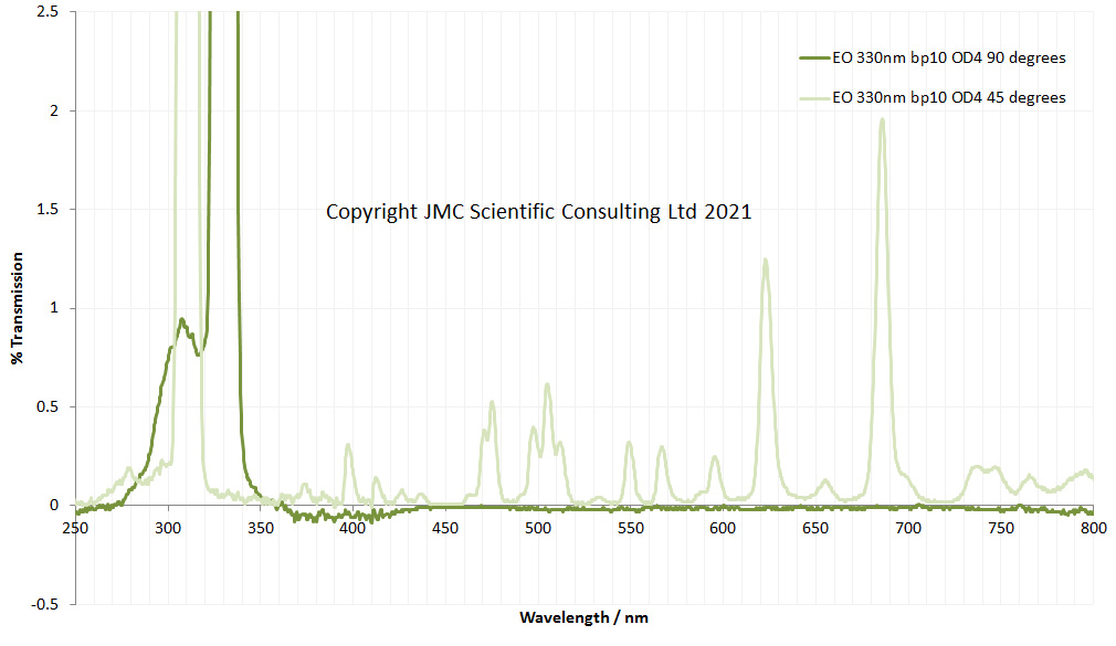
How do these behave? Firstly, the Edmund Optics 330nm, 10nm bandpass filter which claims OD4 blocking (<0.01% in the out of band regions) and has a mirror finish on both surfaces of the filter as a result of coatings.
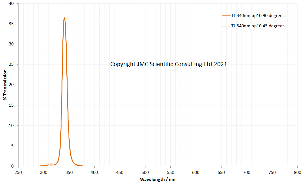
And next, the Thorlabs 340nm 10nm bandpass filter.
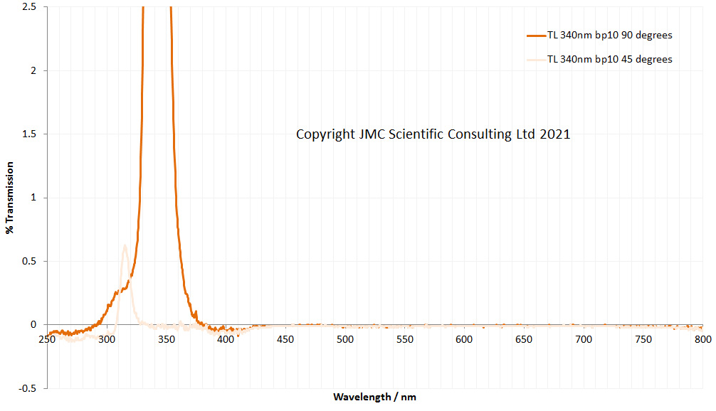
First, I should mention that the Edmund and Thorlabs graphs highlight some of the issues when using a solid state spectrometer like the one I have for looking at filters with really sharp peaks, and that is the artefacts that can occur at either side of the main peak in the profiles. The slight dip in transmission below 420nm and above 700nm for them both is not the spectrometers fault. That was all mine. I didn’t recalibrate the baseline while running these 4 filters, so the last two (Edmund Optics and Thorlabs) are showing a slight drop below 0% transmission below about 420nm and above 700nm. It was a sunday morning, I hadn’t had my coffee yet. Excuses over, and despite those effects, how does tilting impact the spectra? With the Edmund Optics filter, peak transmission drops from 330nm to 310nm, and reduces in intensity. Very worryingly though, it starts to let significant amounts of light through across the visible spectra and into the IR. This would be expected to seriously contaminate a UV image if not dealt with properly.
The Thorlabs filter peak transmission drops from 340nm to about 315nm, along with a huge drop in intensity. However unlike the Edmund Optics filter, it doesn’t develop obvious leaks in the visible or IR region (at least up to 800nm).
I should emphasize at this stage that these Edmund Optics and Thorlabs filters have not been developed for use as camera filters, and are designed to work with the light hitting them at 90 degrees to their surface, so it is not unexpected to see their performance being degraded when the light hits them at 45 degrees. Also, I’m not clear on whether other filters in their ranges behave in exactly the same way. Dichroic filters are tailored for the wavelength they are to be used at, as such they could well vary in the transmission they show at different angles.
If you’ve made it this far and are suffering from graphical overload, you can now take a breather – no more graphs. Why are these changes important and more importantly, what can be done about them if using these filters for photography?
As for the ‘why’ consider how light goes through a lens and reaches a camera sensor. It doesn’t just come from directly in front of the camera, but as a cone of light. The wider the focal length of the lens, the wider this cone. 45 degree either side of normal to the lens is pretty wide, equating to a focal length of about 22mm on a camera with a sensor the size of a 35mm SLR. As a result of this the spectral distribution of the light reaching the edges of the image could be very different to the light in the middle of the image, leading to strange colour shifts across the final UV image.
The 45 degrees used for the test here is a pretty tough harsh based on this, and the effects would be expected to become less severe as the angle gets closer to 90 degrees to the surface of the filter. For example a 105mm focal length lens has angle of about 23 degrees on a full frame (35mm) sensor camera. On longer focal length lenses, like a 105mm one, the effects described here would be expected to be much less pronounced.
What can be done about this? Longer focal length lenses will be less of an issue, so be aware that dichroic filters can have an issue when using wide angle lenses. Use a good and appropriately sized filter hood to block as much light coming in from the side as possible. If the mechanics allows for it, try mounting the filter behind the lens (between the lens and body of the camera). Although be aware that mounting a mirror finish filter just in front of the sensor can present its own problems with reflections. Perhaps the most obvious thing to do is consider using an ionic glass filter stack instead of a dichroic one. If the slightly reduced transmission is something you can live with, and there is no need for ultra sharp cutoffs to the light, then this can be the most flexible approach and can be used on a wide range of focal length lenses without changing the spectral distribution of the wavelengths getting through to the sensor.
This aim of todays discussion is not to have a downer on dichroic filters – they are extremely useful, offering high transmission and well defined cutoffs – the aim is to point out that depending on how they are being used they can have issues which need to be dealt with to get the best out of them.
There’s been a lot of graphs today, so well done if you’ve made it this far. Thanks for reading, and if you want to know any more about this or any other aspect of my work, you can reach me here.