Sometimes in the world of photography we fall into the trap of ‘must buy that expensive lens everyone has been talking about’. However it is possible to use rather humble lenses to take good photos and they can often produce very high quality images for what is a very modest outlay.
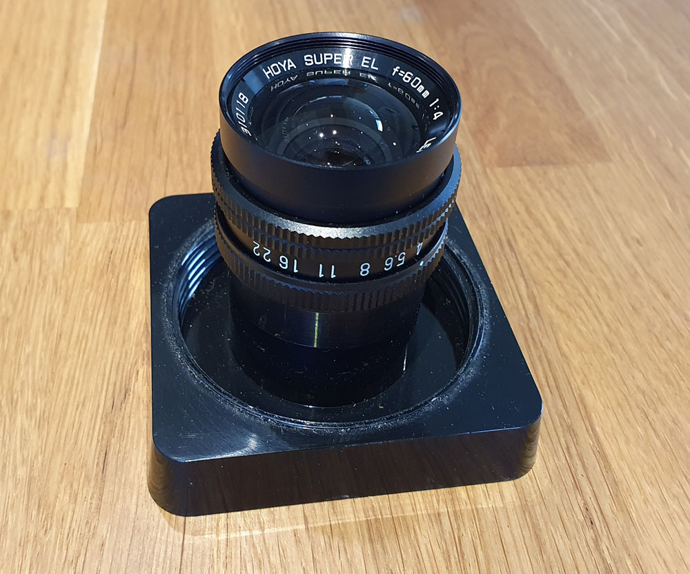
Enter the Hoya Super EL 60mm f4 enlarger lens. This one cost me the princely sum of £30 on ebay. Here’s the lens;
Hoya Super EL 60mm f4 enlarger lens
As mentioned above this was a lens for an enlarger. It has a rather unusual 8 element 4 group lens construction and was designed to cover 6x6cm. The thread is M39 (common for enlargers) and is easy enough to adapt to M42 which is mountable to most cameras with an adapter. I used a helicoid on mine to, to allow me to vary the focus more easily.
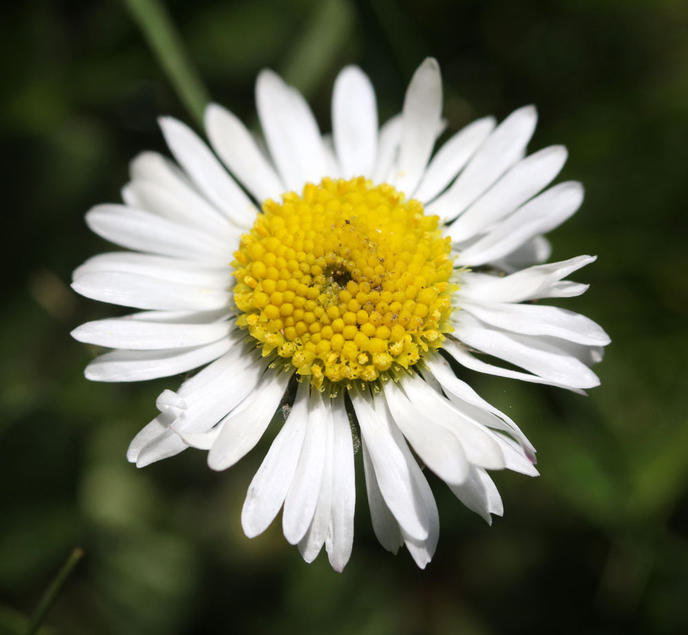
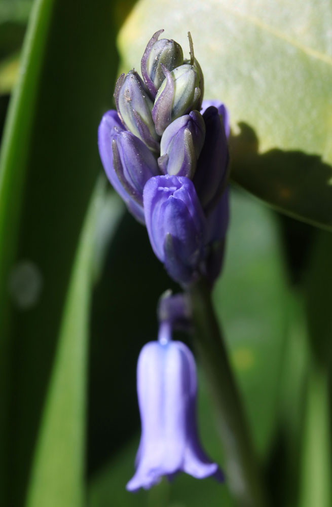
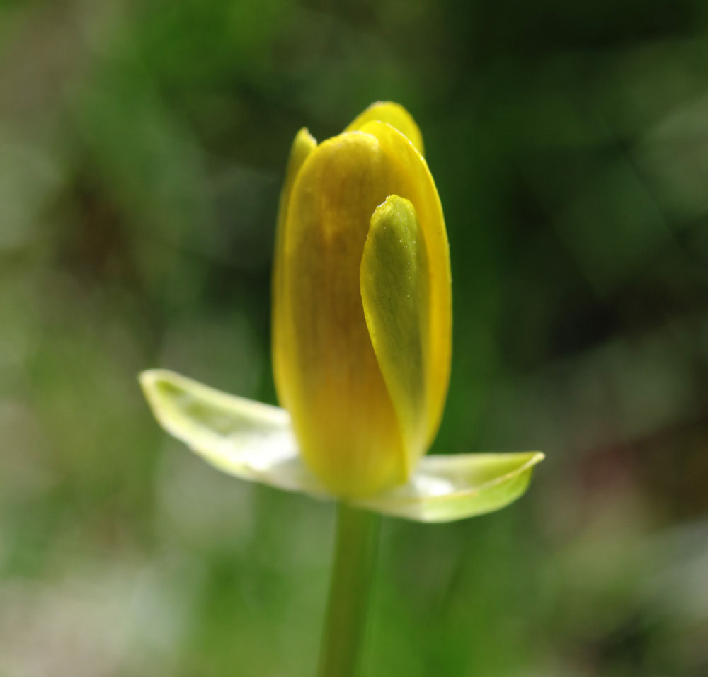
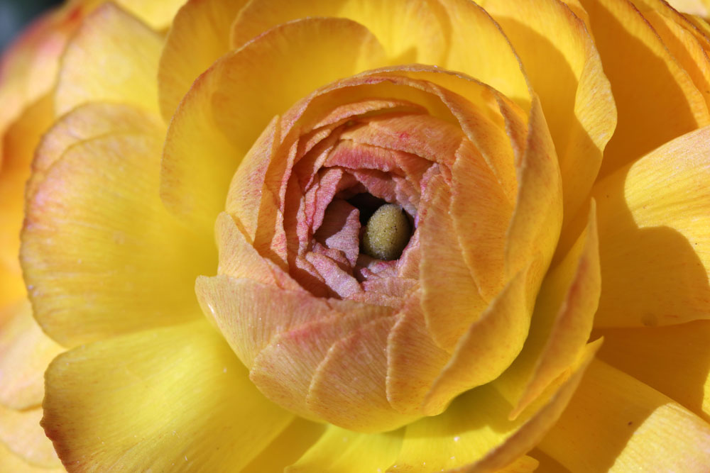
What are the images from it like? Here’s a few from the garden, taken at either f8 or f11 on my Canon Eos 5DS R and hand held. I’ve reduced the resolution for easier sharing here.
Overall I like the images it produces, and the colours are nice. But how about resolution? The image below was pretty much the full frame of the original shot.
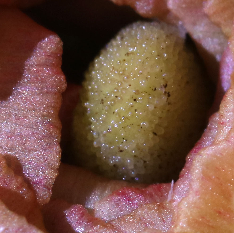
And now a crop from the middle of the flower image, kept at the original pixel resolution (i.e. not reduced for sharing).
I think there is plenty of sharpness there.
Enlarger lenses like this tend to make very good macro lenses and can often be had for very little money. Normally they are M39 threaded as well, so once you have the right adapters for your camera it is easy enough to swap between them if you want to try different ones.
We often want the latest and greatest in terms of equipment, but always keep in mind that new equipment isn’t everything. Also, check out the abundant web resources such as the MFlenses forum, and Photomacrography.net for inspiration and get snapping.
Thanks for looking and if you’d like to know more about this or my other work you can reach me here. And please remember that the images in my site are copyrighted to JMC Scientific Consulting Ltd. If you’d like to share them, please ask first.
Measurement of lens transmission in the UV has interested me since I started working with UV photography, and a I’ve ended up building my own system for determining it (see here). However with this setup I was limited to UV and only just getting into the visible, as it could measure from 280nm to 420nm. With recently being in a position to evaluate an Ocean Insight STS-NIR microspectrometer (initial work discussed here) it got me wondering whether I could now measure transmission from 280nm all the way up to 1100nm, as this covers most of the range of camera sensor sensitivity.
To measure lens transmission over such a wide wavelength range meant juggling light source and spectrometer. I ended up using the following combinations;
280nm to 420nm – Hamamatsu LC8 200W xenon light source, Ocean Insight FX spectrometer.
420nm to 650nm – Moritex MHAA-100W halogen light, Ocean Insight FX spectrometer.
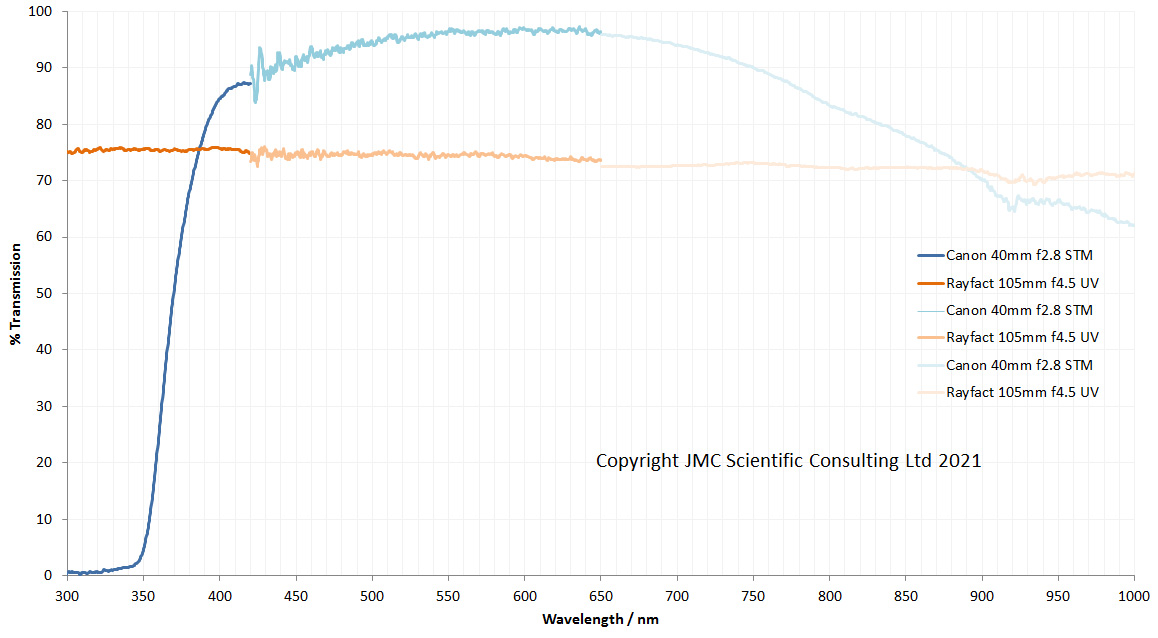
In theory these combinations should have allowed me to see all the way from 280nm to 1100nm. For an initial test I looked at 2 very different camera lenses – Canon 40mm f2.8 STM pancake lens, and a Rayfact 105mm f4.5 UV lens (the modern version of the UV Nikkor 105mm). Here’s how the two lenses looked.
The graph above contains 6 lines – 3 each for the 2 lenses, with each line covering a different spectral range. You’ll notice that the wavelength range only goes to 1000nm, not to 1100nm where the STS-NIR can measure to. This is for a couple of reasons – my Moritex light source light intensity is dropping quickly above 1000nm, and the STS-NIR sensitivity also drops as you get closer to 1100nm. Add these factors together, and then throw in the integrating sphere needed for doing lens transmission measurements and it means that the data gets very noisy above about 1000nm. So I decided that it was only worth plotting it to 1000nm. While I had measurements from 280nm, I started it at 300nm on the graph to make it look prettier – starting at 280nm would make the x-axis scale look odd.
What does this tell us about the 2 lenses? The 2 lenses behave very differently to each other. The Rayfact 105mm f4.5 UV lens has a relatively flat transmission spectrum from 300nm all the way to 1000nm, varying between about 75% at 300nm to about 70% at 1000nm. This is actually pretty close to the data Rayfact share for the lens, which starts at about 78% at 300nm and drops to about 70% at 900nm. The Canon 40mm f2.8 STM pancake lens is very different. It very effectively blocks the light below 350nm, but in the visible region has very good transmission – up above 90% for most of the visible spectrum. Its transmission then drops quickly in the IR as the wavelength increases. This is not surprising, as understandably the Canon lens is optimized for imaging in the visible spectrum. The visible spectrum data is a bit noisier than I expected, especially towards 420nm. Longer acquisition times would help there.
What have I learned here? With the light sources and spectrometers I have I can measure lens transmission from deep in the UV all the way up to the IR. Sensitivity at the top end is lacking a bit which limits me to about 1000nm, although I have a couple of ideas about how to address that in the future. Lens alignment is critical for the measurements here. My setup is horizontal and to get the most accurate results I need to make a stand for each lens to be tested to hold it in exactly the right position for all the measurements. With a vertical setup this would be easier, but at the moment I have no way of safely positioning my lights in a vertical orientation, so horizontal it is for now.
Thanks for reading and if you’d like to know more about this or any other aspect of my work, I can be reached here.
As small business owner working in the research and development area, it is vital for me to keep expanding my capabilities and refining the portfolio of what I can offer to clients. Although I already have a wide range of UV, visible light and IR imaging equipment, along with UV and visible spectroscopy capability (Ocean Insight FX spectrometer), which I use for looking at lens and filter transmission, IR transmission spectroscopy is an area which I am currently lacking. Given the financial upheavals of the last 12 months, the decision to invest in a new piece of kit is not made lightly and new kit must fill a gap in my measurement ability.
My spectroscopy interest is driven mainly by my photography. Camera sensors are mainly sensitive between about 300nm and 1200nm, so this is my area of interest. My Ocean Insight FX spectrometer covers my needs from 250nm to 800nm, and I’ve been very happy with that over the years. Going above 800nm is something I’ve been thinking about for a while, as understanding the behavior of filters for UV photography in the IR is very important – even small leaks in the IR region can be a huge problem for UV imaging. In an ideal world I’d like a spectrometer that would be good for up to and just above 1200nm, however that is a bit of an issue as standard solid state spectrometers tend to only be good up to about 1100nm. Above that you tend to get into more exotic sensors such as InGaAs (indium gallium arsenide) and the costs go up very quickly. As a compromise then, I decided to look at the IR ones with conventional sensors and able to measure up to 1100nm. Between 1100nm and 1200nm the camera sensitivity is dropping rapidly, so this is a compromise I am willing to accept for now.
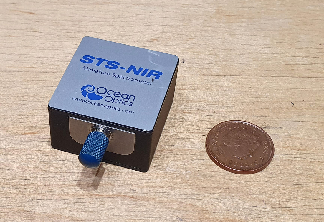
I do a lot of my research from home and my workshop space is limited. As a result of that I tend to look for compact equipment. Combining sensitivity from around 700nm to 1100nm with small size of equipment led me to the Ocean Insight STS-NIR spectrometer and I’ve been fortunate enough to get one of these to evaluate. Initially I was a little skeptical as to whether such a small spectrometer would give good results. And when I say small, I mean small. Here it is in the flesh, next to a 2p coin.
Ocean Insight STS-NIR microspectrometer next to a UK 2p coin
This spectrometer is tiny – 40x42x24mm – with a fiber optic connector at the front, and a USB socket at the rear. Could this really give good data from 650nm to 1100nm?
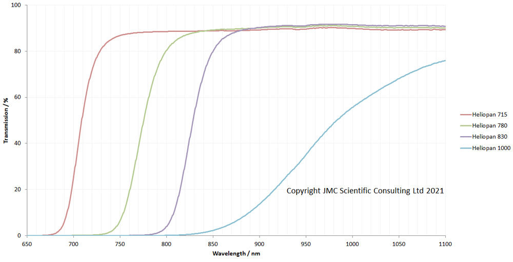
As a first test I decided to look at a range of IR photographic filters – Heliopan 715, 780, 830 and 1000 – which I use for IR imaging. Light source wise I used my Ocean Insight DH-2000-BAL and set everything up for transmission measurement. Here’s how the filters look.
Heliopan 715, 780, 830 and 1000 IR filter transmission
Well, that was pretty impressive for an initial test. The filter transmission curves were as expected and very clean. Up in the 1000 to 1100nm region, the data get a little more noisy, but the sensor is losing a bit of sensitivity up there and the light source is dropping in intensity as well.
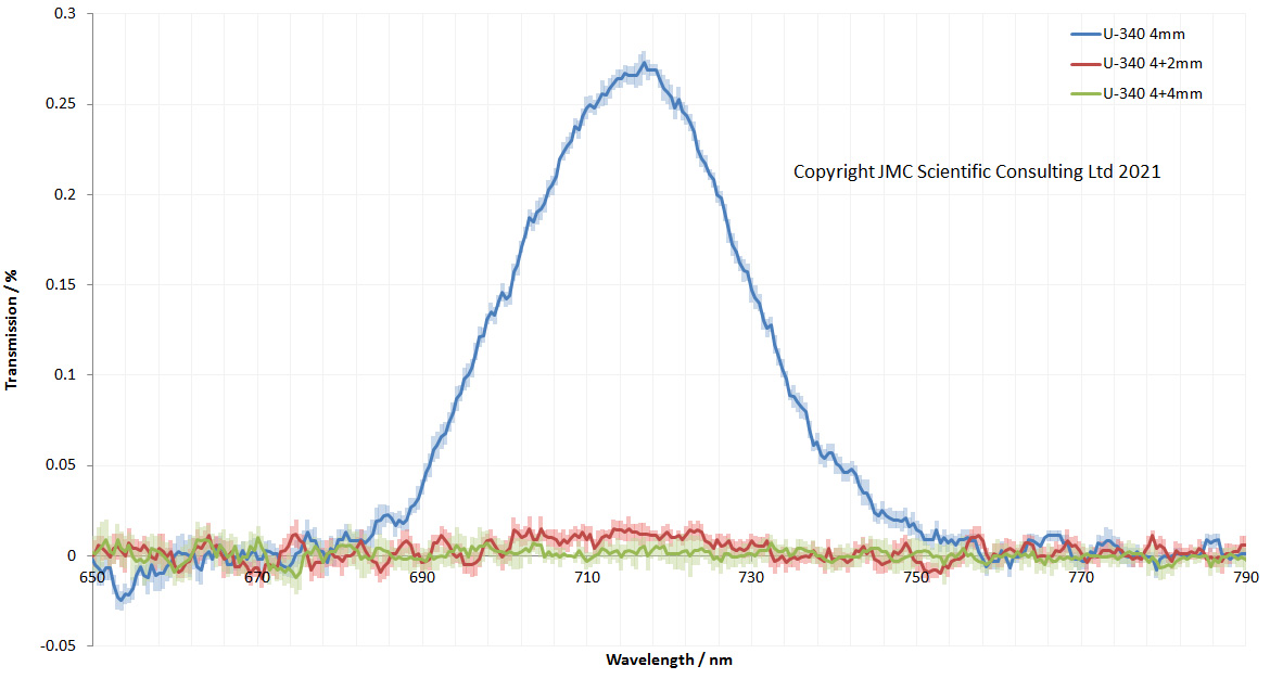
As a next test I took some of my Hoya U-340 filters (from UVIRoptics), and started stacking them up on top of each other. Hoya U-340 is a bandpass filter which has good UV transmission, but does have an IR leak at around 725nm. Using a combination of 2mm and 4mm thick ones I measured the transmission of 4mm, 6mm (4mm+2mm), and 8mm (4mm+4mm) between 650 and 1100nm.
Hoya U-340 transmission at different thicknesses
Each of the lines above was the average of 10 individual runs, and the standard deviations of the scans are shown as paler coloured error bars on either side of the lines. As expected the 4mm Hoya U-340 showed an IR leak of about 0.25% at around 725nm. This leak was nice and clean with the STS-NIR. Above about 1020nm the data for all three filters gets a bit noisy – as mentioned above the sensitivity of the sensor is low up there at the extreme top end, and the light source intensity drops too, so I’m not surprised to see that.
How about if we zoom in to the the 725nm and look in a bit more detail?
Hoya U-340 filters of different thicknesses – transmission in the 725nm region
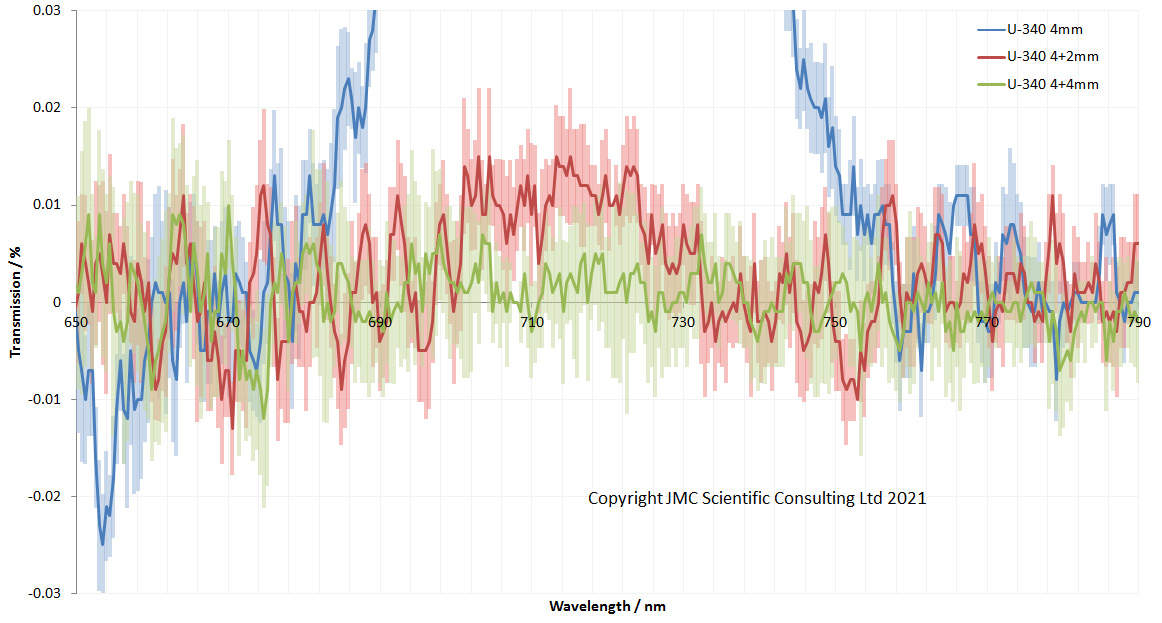
The standard deviation error bars can be seen more cleanly like this and it shows very good reproducibility. The leak in the 6mm stack looks to still be visible and different to the 8mm stack. This can be seen more clearly by zooming in yet again.
Hoya U-340 filters of different thicknesses – transmission in the 725nm region, zoomed in
At this scale, the leak in the 6mm stack at 725nm can still be seen, as about 0.01% (this equates to Optical Density OD4 blocking of the IR). By the time you get to 8mm thick, the leak can no longer be seen due to the extra thickness of the filter stack. So, again, very impressive result from the little STS-NIR microspectrometer.
What have a learned so far? I’ve been very surprised and impressed by the Ocean Insight STS-NIR. For such a small spectrometer it gives very good results. It’s proved that it is capable for assessing filters, and I hope to try it for looking at lens transmission too, although this will be a bigger challenge for it (and my light sources). In theory with the lights I have I should be able to measure lens transmission between 280nm and 1100nm using the FX and STS-NIR spectrometers, which will cover most of the area that normal camera sensors are sensitive too.
Thanks for reading and I hope you enjoyed my latest foray in the measurement world. If you’d like to know more about this or any other aspect of my work, you can reach me here.
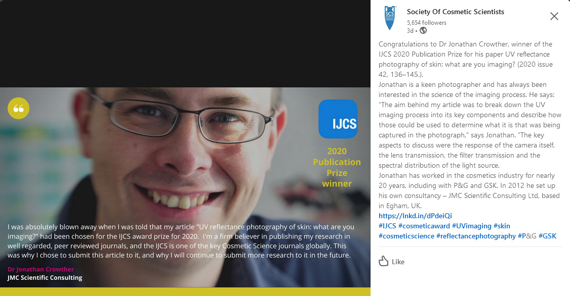
The award has been sponsored by the Society of Cosmetic Scientists and the paper was aimed at demystifying the aspects of the UV imaging process to enable researchers to understand what it is they are actually seeing. It brings together various aspects of my research, and many of the methods I’ve developed and built myself to characterise cameras and lenses in the UV region.
I’ve always been a firm believer in the peer review process for the critiquing and publication of research, and will continue to actively publish my work in this area in the future.
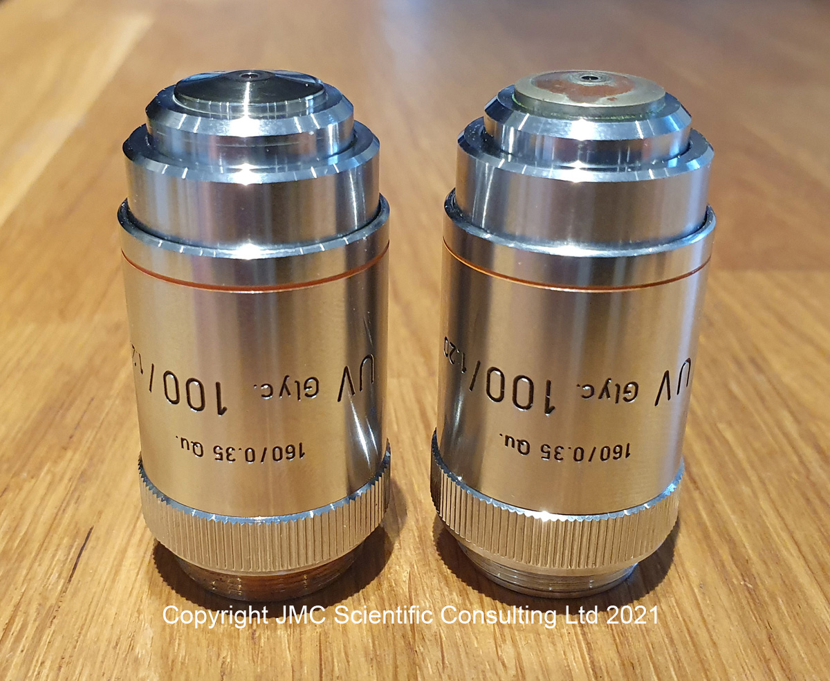
Building my UV microscope has meant a steep learning curve when it comes to the useful items manufacturers have produced in the past. A really steep learning curve. The biggest issue was that the items of interest, such as objective lenses which were made with quartz or calcium fluoride elements, were often made in extremely small quantities. As such there is very little information on them, and tracking down source documents is either very difficult, or in some cases impossible. This brings me to the subject of todays post – the Leitz UV 100x NA1.20 objective. This is a high magnification objective which I was fortunate enough to obtain a copy of a few months ago, and have written about here. I keep an eye out for these and a few weeks ago found another one for sale for a reasonable amount of money, and decided to buy it as a back up copy. When it arrived, I noticed that while it looked similar to the one I already had, it was not identical. So let’s take a look at them and see what is going on with them. Here are the two objectives, my original one on the left, and the new one on the right.
Two Leitz UV 100x objectives. Front view.
From the front, these two objective look the same as the labels are identical. The difference becomes obvious when they are turned around though.
Two Leitz UV 100x objectives. Rear view.
The one I got originally had “Leitz Wetzlar” and “Germany” written on the back, and that was also present on the new one. However the new one also has a 9 digit code number engraved in red on it. It also had a number “2” scratched into it. The engraving looks to be professionally done. Trying to track down the significance to this engraved number has been difficult. I’m not even 100% sure on what it is yet, but it seems to be an identification number from Leitz for a pre-production or prototype version of the objective. Interestingly I have another objective lens (a 50x phase contrast NA1.00) with a similar type of code on it, here, and I’ll come back to this one later.
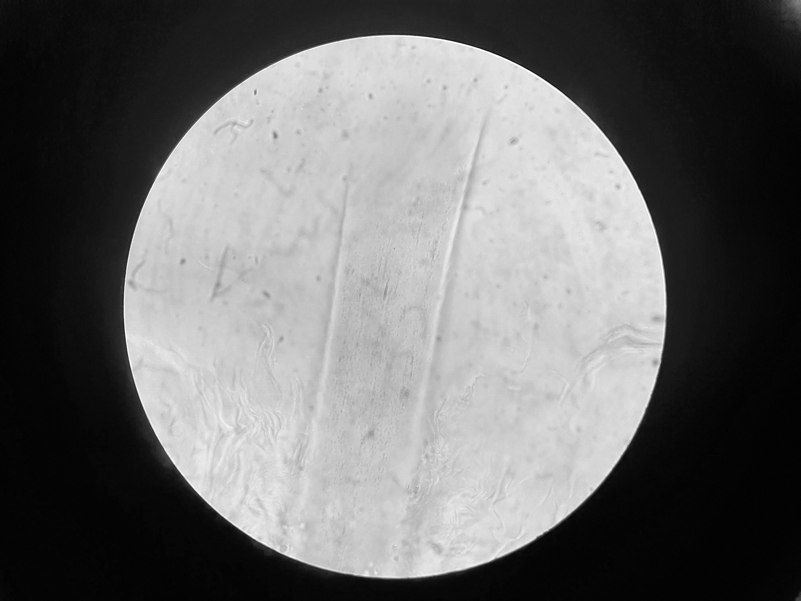
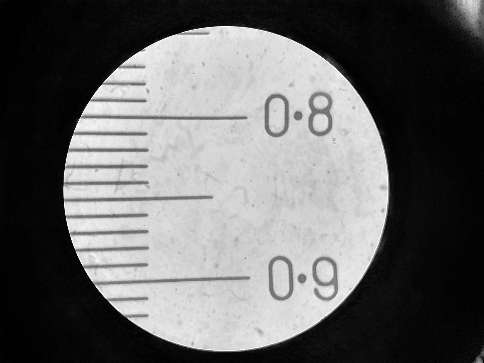
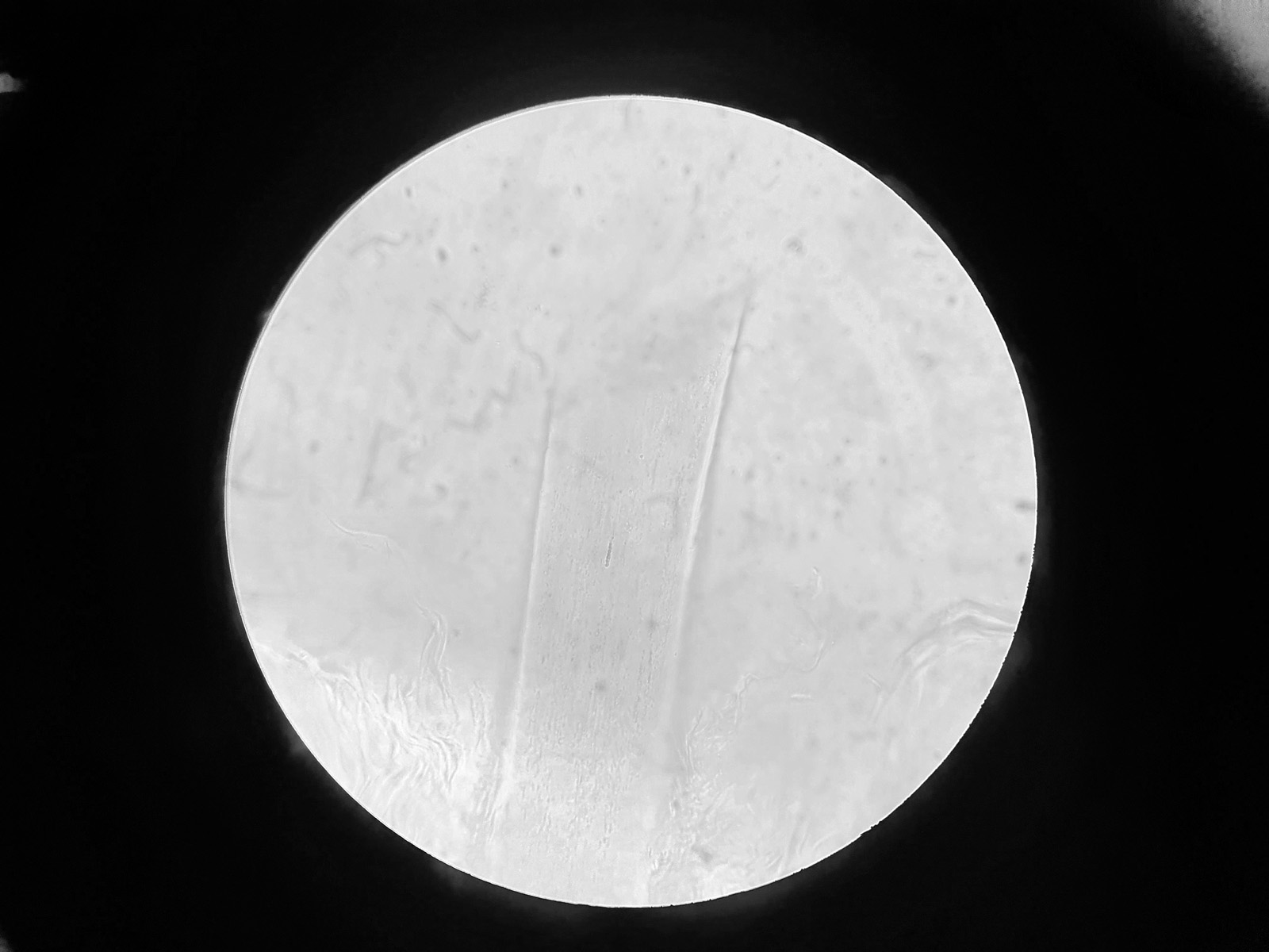
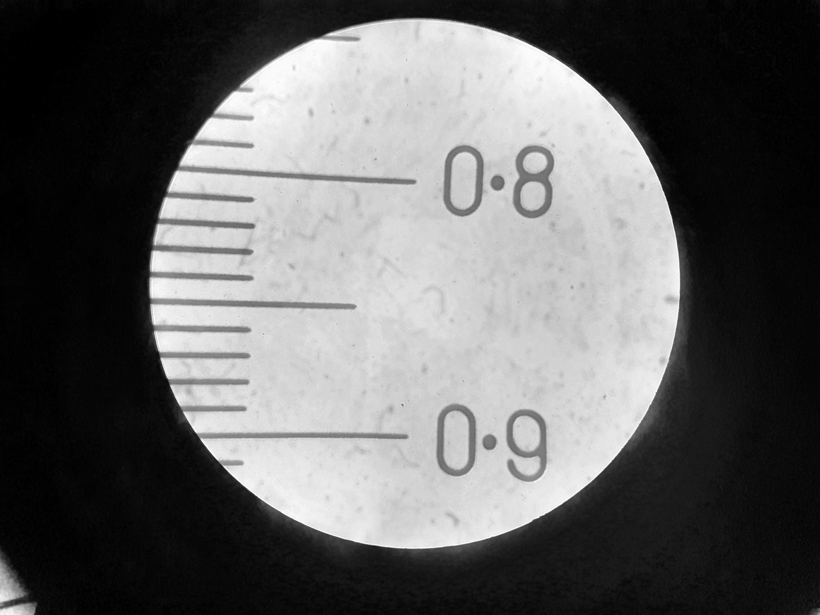
How to the two compare? Some quick brightfield images of a hair on a slide of human skin, and a measuring graticule are given below (taken as a single shot through the eyepiece using a phone). Firstly, for the new one.
Hair on a human skin slide. New 100x Leitz UV lens with red writing.Graticule. New 100x Leitz UV lens with red writing.
And then the other version of the lens (without the red writing on it).
Hair on a human skin slide. 100x Leitz UV lens.Graticule. 100x Leitz UV lens.
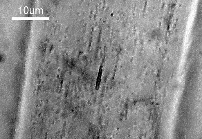
Keeping in mind that these were taken through the eyepiece with my mobile phone, there doesn’t look to be much of a difference between the two objectives. In the middle of the images of the cortex of the hair shaft, there is line of melanin granules. Cropping the original images and boosting the contrast a bit gives the following, again first for the new lens with the red writing.
Melanin in the hair cortex. New 100x Leitz UV lens with red writing.
And now for the other one without the red writing.
Melanin in the hair cortex. 100x Leitz UV lens.
On the face of it, the two objectives look to be behaving similarly. The main reason for my interest in these is because they were designed for use with UV and to be transparent down to and below 300nm. If I compare the transmission through the two lenses, this is where something odd happens.
Transmission through the two 100x Leitz UV objectives.
The original one I had transmitted down to and below 300nm as expected (note these are not absolute transmission values as the lens diameter is small and cuts off some of the beam, reducing the totoal transmission). However the one with the red writing behaves very differently to the original one. Below 400nm the transmission starts to drop until around 320nm. The slight rise again at 300nm for the one with the red numbers is likely an artifact of the measurement and not a real effect.
This is very odd and it doesn’t look as though the one with the red writing has the same transmission in the UV as the other one. Could it be that there are glass lens elements in it, instead of the UV transparent materials which it is supposed to have? Without taking them apart (which I will not be doing) it’s going to be a tough one to answer definitively.
This bring me back to something I mentioned earlier in the post. I have another Leitz lens with red writing on it – the Leitz 50x Pv lens – which I originally discussed here. When I originally tested that lens and measured the transmission I was surprised to find that it blocked the short wavelength UV even though it had ‘Quartzgl’ on the objective barrel, which I assumed meant it was made of quartz. I could not understand why this would be at the time. Could it be that these lenses with the red writing do not have the same optical elements as the final production versions? Perhaps if these are prototypes, they were mainly aimed at prototyping the overall construction rather than the specific optics which were to be used in the final production model, although the 100x ones certainly performs similarly in the visible region. That is purely speculation on my behalf, and unless I can track down an original Leitz employee who worked on them, I’ll probably never find out for certain. Although if I could find another one of the 50x Pv objectives, that would be good to test. So, anyone out there with one, feel free to get in touch.
Where does this leave us? Older equipment can be amazing for those of us involved in research and development, enabling us to buy things which would have been extremely expensive when new, for a fraction of their original price. However we should always remember that rare items such as the ones used for UV imaging were often only made in small numbers, and their suitability for the intended application needs to be verified before they can be used. Test, test and test again. If you’ve made it this far, thanks for reading, and if you’d like to know more about this or any other aspect of my work, you can reach me here.
A few weeks ago I posted some initial work which used a converted high street camera to be ale to make images at 254nm, which is down into the UVC region (see here). Frankly I was stunned to see the camera capture anything at such a short wavelength. The camera used for this was a monochrome converted Nikon d850 from MaxMax, which had had the Bayer filter and microlenses removed. Of the cameras I have, I thought this would give the best shot at seeing that far down, and indeed it did. Some of the folks on the Ultraviolet Photography forum have been looking at image UVC for a while, but until recently I had discounted it as I thought my cameras lacked the required sensitivity to be able to capture anything. After seeing an image with the monochrome Nikon d850, it got me wondering again though about looking at 254nm with a camera with the Bayer filter still in place.
For colour imaging at 254nm, I turned to a Sony A7III which was converted to multispectral imaging again by MaxMax. When this was done I’d requested the sensor coverglass be replaced with a quartz window, instead of being left in place which is normally what happens with these types of conversions. Using the came setup as discussed here, an image of the feather in a vase was captured along with the diffuse reflection standard. After white balancing this was how it looked.
254nm image captured using a converted Sony A7III camera.
As before I captured an image with a Schott WG305 filter as well to see how much of the image was coming from longer wavelengths, and here’s how that looked.
254nm image captured using a converted Sony A7III camera and WG305 filter in place.
As with the monochrome camera, a faint image was seen with the WG305 in place, indicating what I was capturing at 254nm was not a pure 254nm image, but that there was some contributions from longer wavelengths. However the majority of the image was indeed coming from reflected 254nm light.
I was really surprised with the performance of the Sony A7III and the fact that I could get an image at 254nm with it, with the Bayer filter still in place. Given how much UV was absorbed at 308nm by the Bayer filter, I’d fully expected this to be the case at at 254nm, however it does not seem to be the case, and initial assessment of the images suggests that the Bayer filter is absorbing less of the light at 254nm than it does at 308nm, although this remains to be proven. Hint, hint, if anyone can deposit Bayer filter dyes on to a quartz plate at thicknesses which are representative of their usage on camera sensors let me know…..
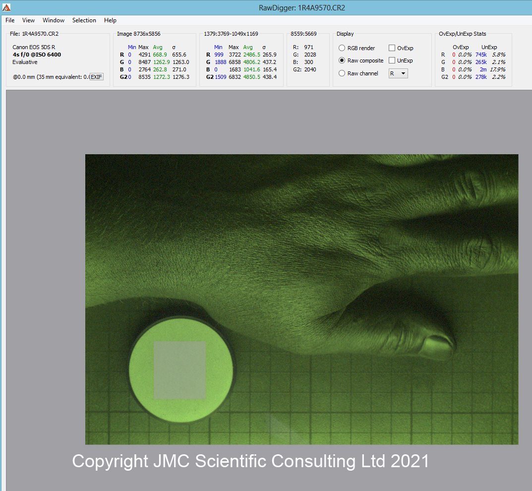
It is possible to get some idea of how the different colours in the Bayer filter are transmitting the light from RAW files. Looking at a 308nm image in RawDigger as a Raw composite file you get a distinctly green colour cast to an image taken with a multispectral converted camera, as shown below.
308nm image from a multispectral converted Canon EOS 5DSR.
The image above was taken with converted Canon EOS 5DSR camera using an Invisible Vision 308nm filter. The Raw composite file has a distinct green colour cast at this wavelength, showing the green parts of the Bayer filter have a better transmission here than the red and blue parts. Oh and do not go shining 308nm light on your skin, without doing an extensive safety assessment. You have been warned…..
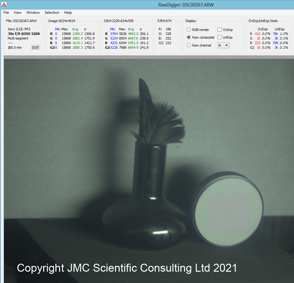
The Raw file from the Sony A7III at 254nm looked like this.
254nm image from the multispectral Sony A7III camera.
At 254nm the green channels response from the diffuse reflectance standard are still slightly higher than red and blue ones, but there is much less difference between them all at this wavelength when compared to 308nm. As a result the Raw composite image has much less of a colour cast to it. This would suggest that the red, green and blue dyes have much more similar transmission to each other at this wavelength than at 308nm, although that remains to be proven.
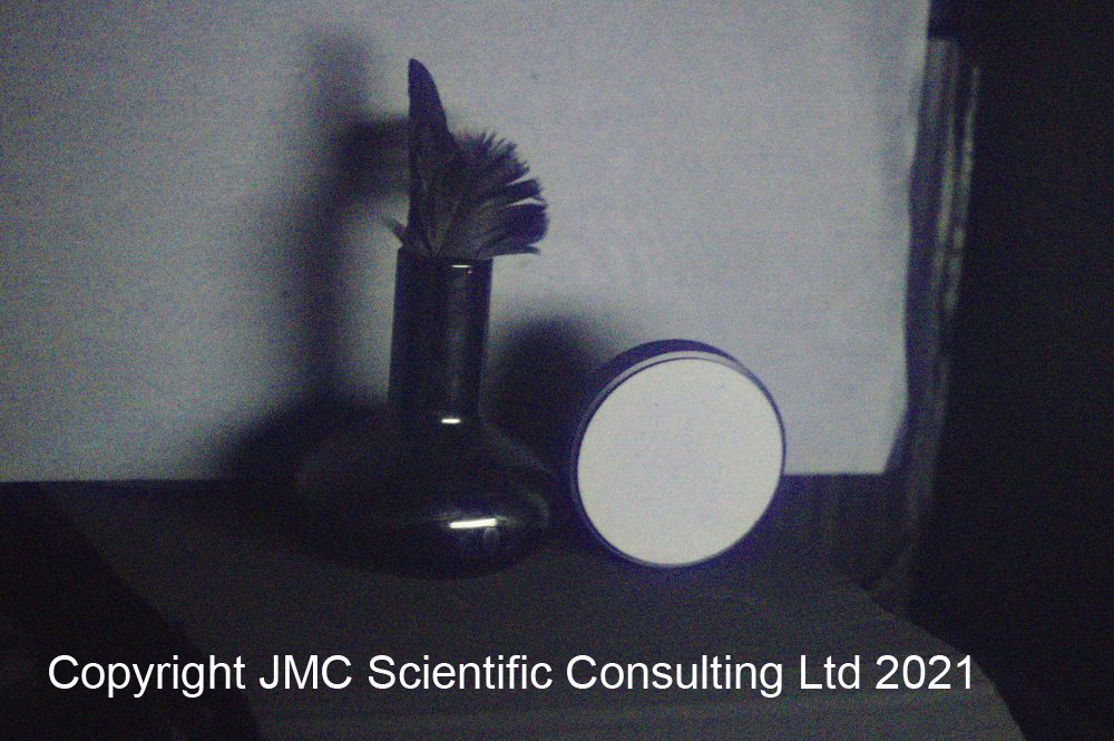
One final thing before I end todays post. The Sony A7III has a quite amazing high ISO performance, so after I’d taken the images above I cranked up the ISO to 102,400, and took an image at 254nm with a 1 second exposure time!!!
254nm image with the converted Sony A7III at ISO102,400 and a 1s exposure.
While obviously noisy, the image at ISO102,400 is quite frankly astonishing, especially when you consider that this was a 1 second exposure at 254nm.
Yet again I have been amazed and surprised by how far into the UV region it is possible to look with what are at their heart commercial high street cameras. Even with the Bayer filter and microlenses in place, it was possible to capture images at 254nm using a converted Sony A7III camera. Thanks for reading, and if you want to know more about this or any other aspect of my work you can reach me here.
Back in April 2020 when Lockdown 1.0 kicked in in the UK, I decided it was time to try and learn a new skill. So it was that I embarked on a journey into the complex and fascinating world of microscopy. What I knew about microscopy at that point could have been written on the back of a very small envelope. Jumping in with both feet and having done practically no research at all into the area, I bought an Olympus BHB from the 1980s, which was, well, in need of a bit of love and attention. Affectionately named ‘Project Beater’ due the condition it arrived in, I started documenting my journey into microscopy here, and have been providing regular updates ever since.
Not long after getting the microscope, I started wondering whether it would be possible to make my own UV imaging system, capable of doing transmission microscopy down to and even below 300nm to help with my sunscreen research. Commercial UV transmission microscopes do exist but they are incredibly expensive to buy. To build one would be a monumental challenge, as glass absorbs short wavelength UV, and microscopes have a lot of glass in them. And when I say ‘a lot of glass’ I really was in for a shock as to how complex making a UV microscope would actually turn out to be. Since then I have been constantly modifying, tinkering, buying (oh, there has been plenty of buying) and tweaking this little Olympus BHB with the eventual aim of removing all the glass from the optical system that leads to the camera, replacing it with UV fused silica and other UV friendly materials.
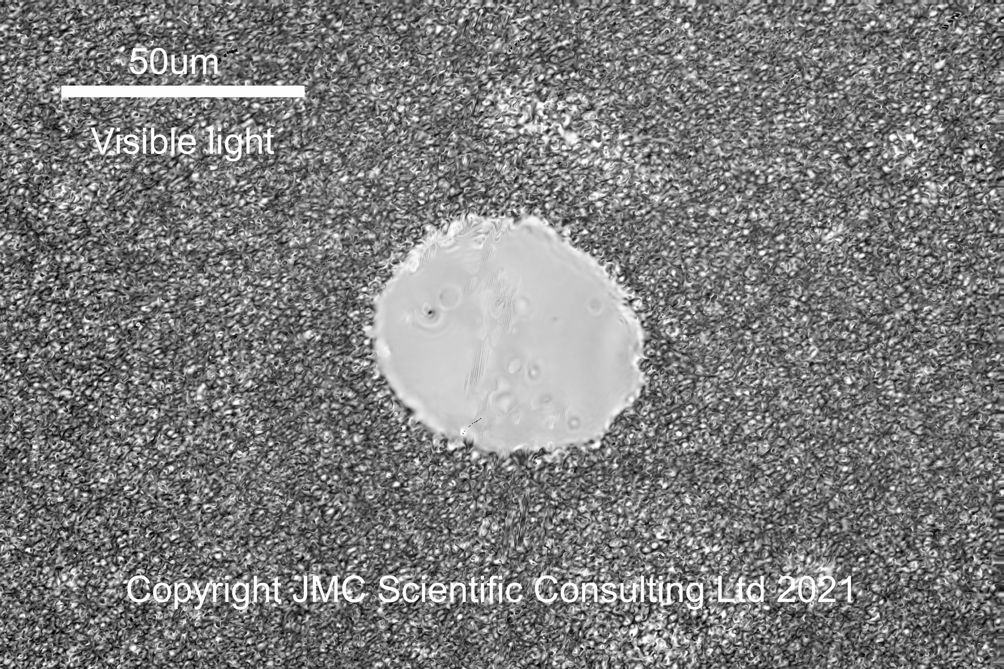
This brings us to February 2021, 10 months after the initial purchase of Project Beater. With the final pieces of the UV conversion carried out, it was time to test it out and see whether it would even be able to image in the UVB region down at 313nm. 313nm was chosen as a test wavelength, as the mercury xenon lamp had a good strong line there, and the camera should still have some sensitivity there (it drops very quickly below that). For a test subject it made sense to use a sunscreen formulation which had a UVB absorber in the oil phase, and no UV absorbing ingredients. This way it should look darker at 313nm than at 365nm or in the visible. After applying a dot of product onto a quartz slide and adding a quartz coverslip, imaging in the visible region with a 32x Zeiss Ultrafluar objective gave the following.
Sunscreen emulsion in the visible region
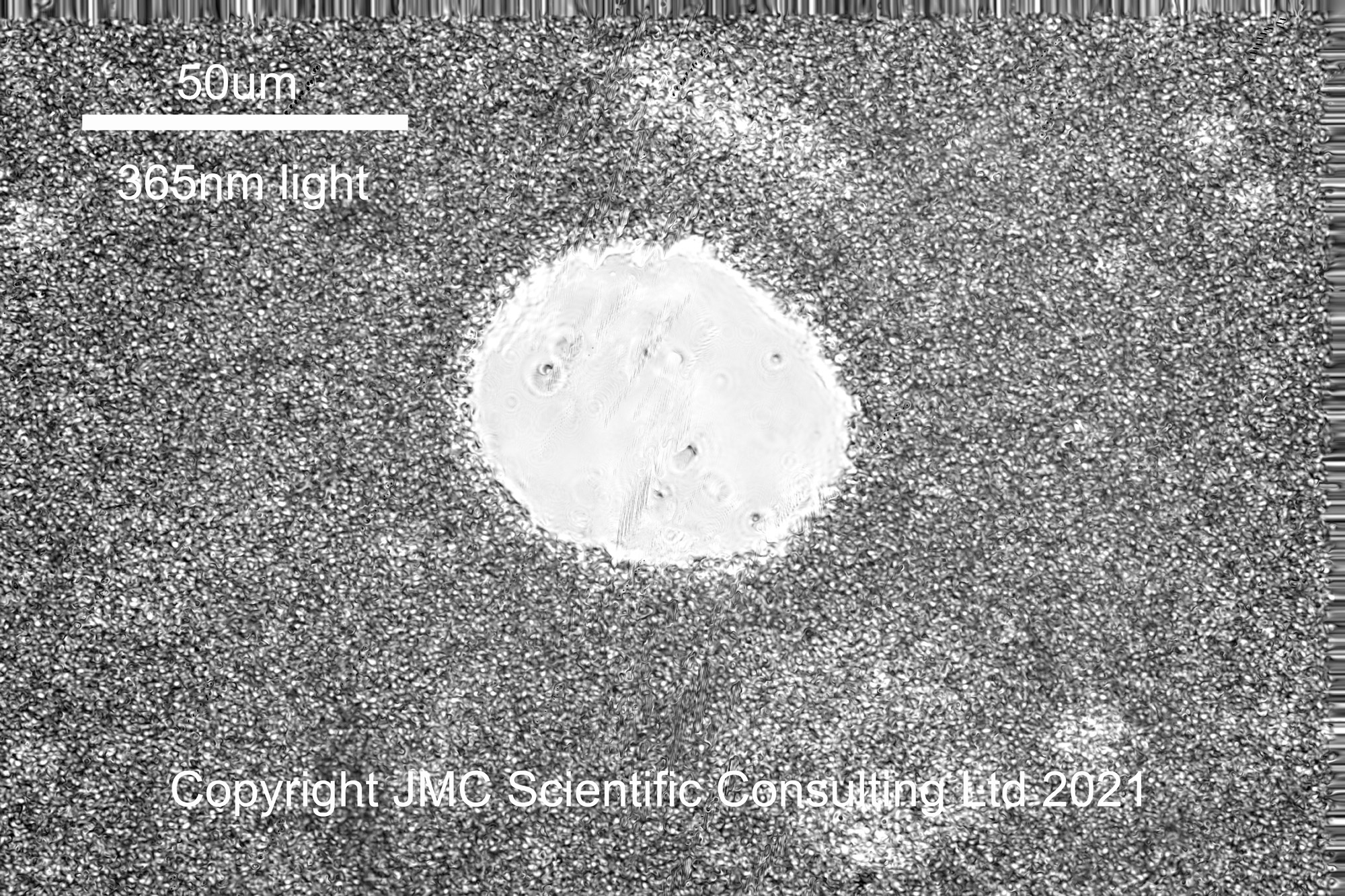
The circular feature in the middle of the image is an air bubble in the formulation, and surrounding it is a dense network of small oil droplets in a water based continuous phase. The next wavelength to image was 365nm (UVA).
Sunscreen emulsion at 365nm (UVA)
365nm was chosen for imaging in the UVA, as the mercury xenon lamp has a strong line there. To filter out unwanted wavelengths from reaching the camera, I used a 365nm bandpass filter from Edmund Optics. This blocks wavelengths outside the region of interest with an efficiency of OD4 (optical density 4, or in other words transmission in the out of band regions is <0.01% on average). The 365nm image looks similar to the visible one, which it should do, given the sunscreen ingredient it contains does not absorb UVA. Something to notice, in addition to the air bubble in the middle of the image, in the visible and UVA images there looks to be regions where the emulsion looks ‘lighter’, specifically to the top right and bottom right of the air bubble. I shall come back to those regions in a minute.
Once the UVA image was captured, I changed the filter for a 313nm UVB one and imaged the area again, getting the following.
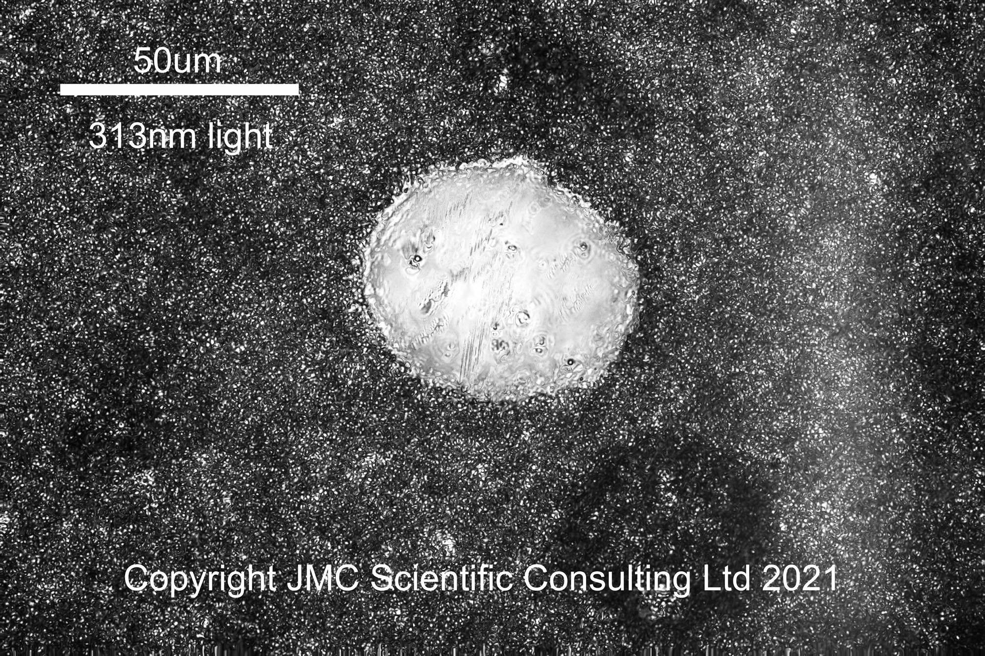
Sunscreen emulsion at 313nm (UVB)
At 313nm the image looks a little different. The air bubble is still visible, but the image looks darker, and those areas which were lighter in the visible and 365nm images now look darker than their surroundings. I suspect these darker areas are oil rich, and the UVB absorbing sunscreen is in the oil phase of the product.
It was great to see a UVB image appear at 313nm. However it certainly has its challenges. With the 313nm filter I have, even though it was rated OD4 for out of band regions, the degree of blocking it offered was not sufficient, and when first tried I was getting some none UVB light coming through to the camera. I had to use another 310nm OD4 bandpass filter in series with the first one, to block unwanted wavelengths (unfortunately I didn’t have a second 313nm filter, but the 310nm still let the 313nm line through). Camera sensitivity was very low at 313nm, and I had to increase the ISO setting on the camera from ISO 400 for the visible region to ISO 6400 for 313nm, and the time to capture an image increased from 1/80s to 30s!!! When you think that each image above is a stack of about 10 images, with slightly different focal points, you start to realise the logistics involved with trying to capture UV images. Oh and I really need to get better at preparing slides – this sample was not the best. One of the scariest things with making these is the knowledge that a quartz coverslip cost about 20GBP, so there is no ‘use it and throw it away’ as with glass ones. Once finished with the coverslip has to be cleaned along with the quartz slide. At 0.35mm thick to 20GBP each, cleaning a quartz coverslip is not a fun job…..
How to try and visualise how the effect of of converting the microscope to UV has had on the throughput of light to the camera? Back in June 2020 when I did my first UVA imaging of sunscreens, I also did some measurements of throughput of light through the unconverted microscope, shown here. Taking that data and normalising the irradiance to the max peak height gives the following.
Irradiance of lamp and through the original microscope
In the graph above the red line shows the output from the 200W Hamamatsu Xenon lamp. It shows a long tail down into the UVB and UVC region, and there is still light present even at 250nm. The blue line is the light having passed through the microscope. This shows that below 400nm, the UV starts to be absorbed straight away. By 350nm, about 75% of the light has been absorbed by the glass in the optics of the microscope, and by 330nm, there is nothing getting through. I was actually surprised by how much UVA did go through the standard microscope, and in that form it would be suitable for UVA imaging, if used with good objectives and ideally a quartz photoeyepiece.
For the final build, I decided against using the Hamamatsu 200W light source, as logistically it was hard to use. I settled on a Zeiss 50W mercury xenon lamp, which while have a more ‘peaky’ spectrum, has strong lines at very specific wavelengths in the UV region. So how does the transmission through the microscope look now it has been converted to UV?
Irradiance of lamp and through the converted microscope
In this graph we now have 3 lines. The blue line is the 50W lamp alone before it is connected to the microscope. The irradiance spectra has peaks because it is a mercury xenon lamp. The red line shows the normalised spectra after it has passed all the way through the microscope to the photoeyepiece at the top, which is where the camera connects. After the conversion to UV, the light going through the microscope has a very similar profile to the original light source, showing only a small reduction down at 300nm, and even down at 250nm. This is because all the glass has been replaced with UV fused silica, and the objectives and and condenser are quartz, UV fused silica, and calcium fluoride. In this graph there is a third line in green. This is the light that comes out of the eyepieces. I added yellow filters here to block light below about 500nm as a safety precaution (the line is much more noisy than the other two due to the complexity of measuring the output from them). I will however still be using UV safety glasses whenever using this, and also using a UV blocking filter over the input whenever I use the eyepieces for focusing.
The goal when I set out on this conversion was to build a microscope which I could use for visible light imaging, as well as down to and below 300nm. Also, it had to be fairly compact as my work surface is not that big. By converting an existing microscope, and using a Zeiss 50W HBO light source, I managed to keep the size down, and retain functionality for use in the visible light region.
UV Olympus BHB microscope with Zeiss HBO light source
It has been a hugely complicated build, but very rewarding and I’ve learnt so much about microscopy and imaging in general. There are of course areas for improvement. The camera I have has low sensitivity in the UVB and by about 300nm would be unusable. At 300nm and below I’d need a UV enhanced camera, but that would require connection to a computer to run it. The Edmund OD4 filters really need to have 2 of them stacked together at 313nm and below, as individually they cannot block the out of band regions of light. This is costly though. Also, to change filters at the moment I need to remove the camera, so doing multispectral images of the same sample is pretty much impossible. Ideally the best thing to have would be a modified tube from the microscope to the camera, which had a opening to put filters in and out. This would however need to be custom made and will have to wait for now. The main thing I can do though is learn how to prepare slides better, especially for looking at emulsions.
If you’ve made it this far, thanks for reading, and if you’re interested in knowing more about this or other aspects of my research, I can be reached here.
Ultraviolet C (UVC) is something that until recently the vast majority of us haven’t had to be concerned about. UVC is short wavelength UV that is even more energetic than UVB which is what is responsible for burning us when we go out in the sun for too long. Although present in the light emitted by the sun, our atmosphere absorbs UVC before it reaches the ground, so acts as a natural filter for it. As a result of this efficient filter process we are not exposed to it from sunlight. However UVC can be generated on Earth from a some high energy processes such as when arc welding. Recently there has been a huge increase in the number of UVC lamps in the market place, because UVC offer a route to sterilising surfaces, an area which has received much more attention since Covid arrived on the scene last year. Now if you go into a drug store or surf the web there are a massive range of ‘UVC lights’ which claim to be able to clean and sterilise surfaces that are exposed to them. With these becoming more widely available, there is however a bigger risk of exposure to the wider population and that is because of the effects that they can have on skin and eyes. UVC is highly energetic and can result in painful burns on the skin along with damage to the eye if exposed.
This got me wondering whether topical cosmetics products which are designed to protect us from the UVA and UVB in sunlight could also offer protection from UVC light?
Recently I developed an imaging setup which can be used to capture high resolution photos at 254nm which is in the middle of the UVC region (see here). To test this out this question about sun protection products, I took a couple of moisturisers, one with no SPF ingredients, and one with was SPF 30 rated, and applied them to test plates used for in-vitro SPF testing. These plates are made of a polymer called Polymethylmethacrylate (PMMA) which is transparent to UVA and UVB, and slightly transparent to UVC. I dosed the products at about 2mg/cm2 which is the dose used for SPF testing.
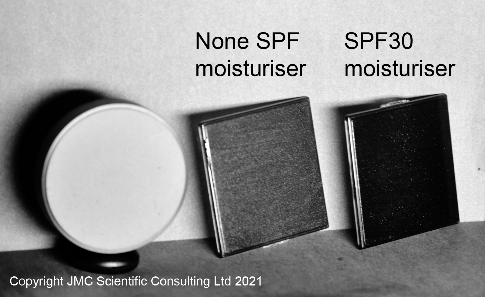
Once applied, I then photographed the plates under 254nm light, to see how they compared and got the following.
None SPF and SPF30 moisturiser under 254nm light
What is the image above telling us? This a 254nm (UVC) reflected light photo, so the brighter areas are reflecting more 254nm light, and the darker areas are reflecting less. The plate with the moisturiser without SPF, in the middle of the image, looks ‘medium grey’ indicating some absorption of the UVC. The test plate itself absorbs some of the 254nm light, however the none SPF moisturiser is absorbing some of light as well – this not surprising as UVC is absorbed by organic material, and the moisturiser is an oil in water emulsion. The SPF30 moisturiser is much darker than the none SPF moisturiser though. This indicates that the SPF30 moisturiser is absorbing much more of the UVC radiation than the SPF free version. Although designed to protect the skin against UVA and UVB, the SPF30 test product is also absorbing UVC.
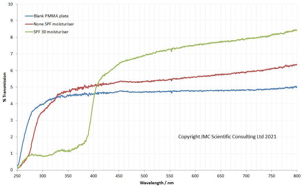
While I had the PMMA plates with the moisturisers on them, I thought I would run the transmission spectra through them on my Ocean Optics FX spectrometer, just to see what they looked like. First set of scans is between 250nm and 800nm.
Transmission of the PMMA plates between 250nm and 800nm
So what is going on with these transmission spectra? The blank PMMA plate has a fairly flat transmission spectrum between about 300nm and 800nm. Below 300nm though, transmission drops rapidly and by 250nm it is almost opaque. It should be noted that the surface of the PMMA plates are rough, which is why the max transmission isn’t very high. Actually when the moisturisers are put onto a plate, max transmission in the visible part of the spectrum becomes higher than the blank plate. This is because the moisturiser smooths the surface that the light comes into contact with, and thereby reduces the scattering, and increasing the amount of light that can pass through the plate.
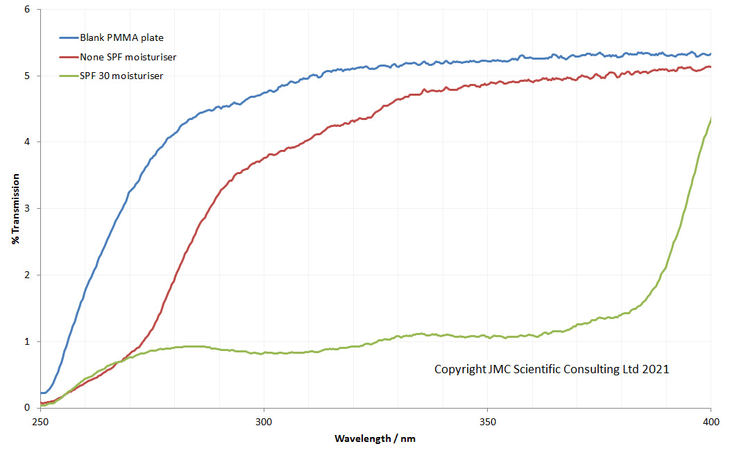
Below 400nm, the moisturisers behave differently, and this can be seen more easily if I just plot the 250nm to 400nm region.
Transmission of the PMMA plates between 250nm and 400nm
Below 400nm, we can see how the SPF product absorbs much more UV between about 275nm and 400nm when applied to the PMMA plate. Both products absorb some of the light at 250nm, although as can be seen the PMMA plate itself is also absorbing most of the UVC that far down. The transmission spectra shown here don’t fully explain the photograph of the moisturiser coated plates, in which the SPF product looked darker than the none SPF one at 254nm. The photos are looking at reflection of light from the subject, while the transmission spectra are just that – transmission – and this may be accounting for the difference between what the photo and spectra are saying. What’s even more obvious is that the PMMA plate is not really suited for transmission measurements when you get down to 250nm. This it not a huge surprise as it was not designed for that. It does mean though that these are not ideal for use as a transparent substrate at 254nm, but I have some ideas about what to use down there.
The last 12 months have seen rapid changes to our lives, some of which brings additional risks which we need to think about. The availability of UVC lights to the wider population has exploded, and along with that there comes to risk of skin damage from exposure. UVC photography enables this invisible light to be imaged and also to visualise how it interacts with surfaces, and as can be seen here whether topical skin care products can be used to absorb it.
Thanks for reading, and if you’d like to know more about this and any other aspect of my work, you can reach me here.
With some experiments, the end result is fairly easy to predict. Others, not a chance. With this piece of work I had no real idea what to expect, or even whether I’d be able to see anything at all. Essentially, it was this – can I image at 254nm using the equipment that I already have?
To start with some background. I have an interest in UV photography because of my work on sunscreens, and as part of my research in the area, I’m always looking to push the limits of what can be photographed with the kit that I have. My monochrome converted Nikon d850 camera has a really nice sensor for UV, visible and IR imaging, and I was able to measure the spectral response of it down to 280nm which is the limit of my measurement capability. At 280nm there was still a little bit of sensitivity there, but it had dropped to almost nothing and I’d assumed (always dangerous) that below 280nm it would be essentially zero. When it comes to UV imaging, very often specific wavelengths are discussed, as they correspond to lines in the mercury emission spectrum. 365nm and 313nm are quite strong emission lines, and they lay within the UVA and UVB regions respectively. However drop below 280nm and you get in to the murky world of UVC. While there is UVC in light coming from the Sun, it does not reach ground level as the atmosphere blocks it. However there are artificial sources of UVC. Welders are often exposed to it due to ionisation of the air and metal, where it can result in bad burns to skin and damage to the eyes, and in our new Covid related world UVC sterilisation of surfaces is becoming more and more widespread. This got me wondering whether I could break through into the UVC region and capture photos at 254nm which is another one of the strong mercury emission lines.
This would be no simple task. Even if the camera was sensitive enough to capture an image there, the sensitivity it has would be extremely low, meaning that the presence of any other wavelengths would completely swamp the signal from 254nm. Therefore really good filtration would be needed. For the filter I used a 254nm bandpass filter I got from a Sirchie forensics camera a while back. While it has relatively low transmission at 254nm, it has good out of band blocking, and it meant I didn’t need to spend a fortune on a new filter. Any glass in the lens would absorb the UVC, so I chose the 105mm Rayfact UV lens for this experiment – it has quartz and calcium fluoride lens elements instead of glass and is good for using down to around 220nm. Camera was my monochrome converted Nikon d850 from MaxMax. When I had this made I requested a fused silica sensor window, in case I ever wanted to go below 280nm. Light source was an interesting one. In the end I got a pair of 8W 254nm UVC fluorescent tubes from ‘a well known internet auction site’. These are normally used for sterilisation of water, but they fit my UVP UV lamp so I thought I’d try them out. Subject wise, a small vase with a couple of feathers and a Spectralon 20% diffuse reflectance standard was chosen.
For imaging, everything was done in a dark room, and the subjects were placed in a box painted with Semple Black 3.0 paint which has low reflectance and low fluorescence, to cut down on stray light. I wore UV protective glasses (in fact that point deserves capitals – I WORE UV PROTECTIVE GLASSES – please do not play around with UVC lights without wearing these). In addition to imaging the subject using the 254nm filter, I also took another image with a Schott WG305 long pass filter in front of the 254nm filter, to check for stray light getting through.
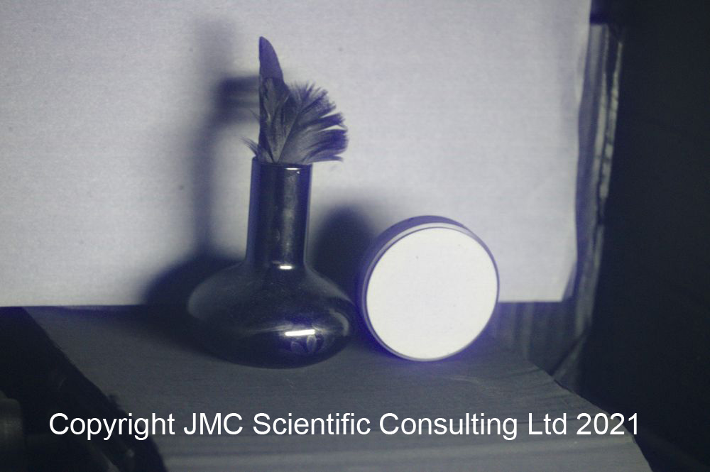
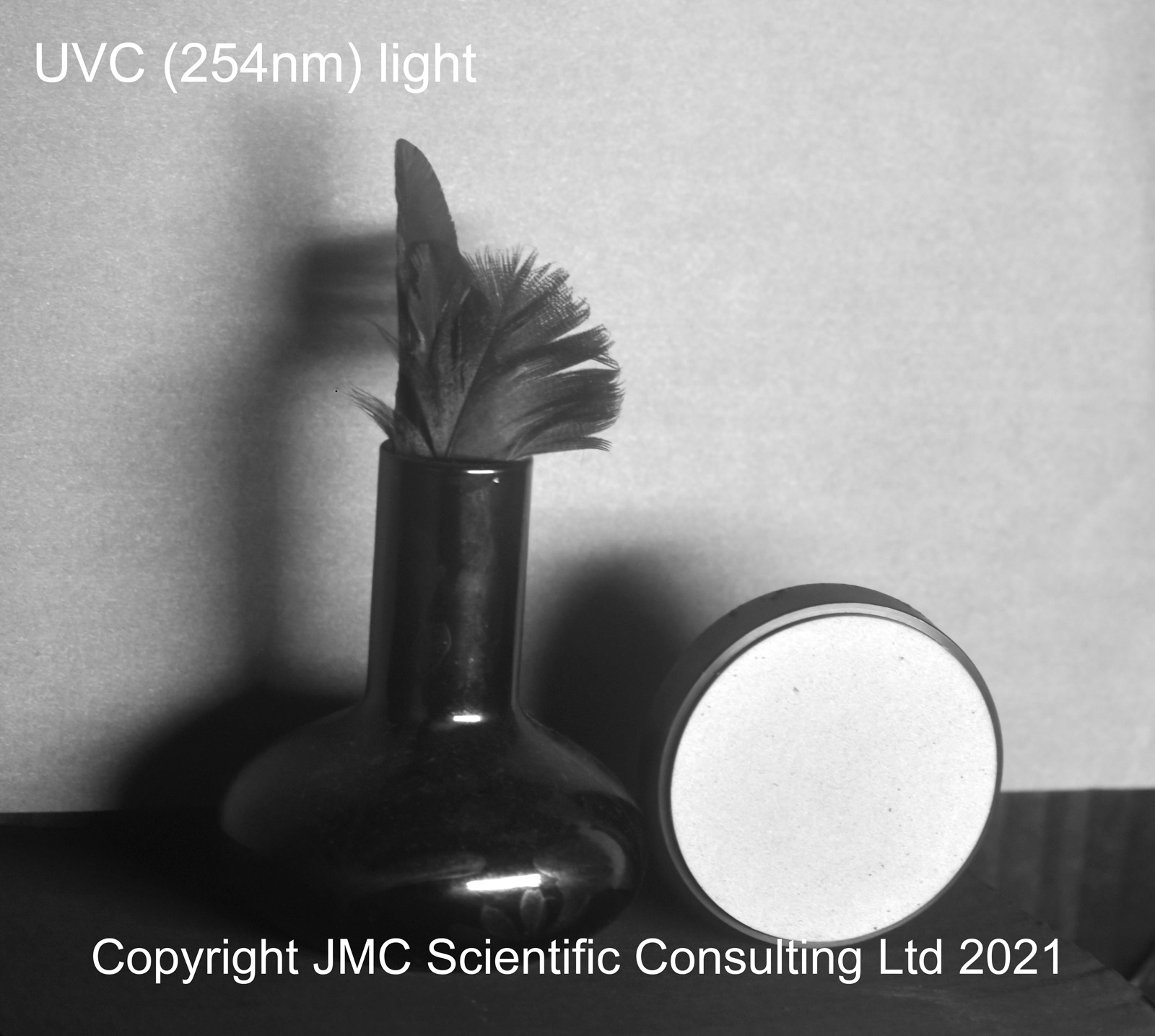
Right, that is far too much waffle. Was it possible to capture a UVC image with this setup? Well, yes it was, and this is what it looks like.
UVC image captured with the monochrome Nikon d850
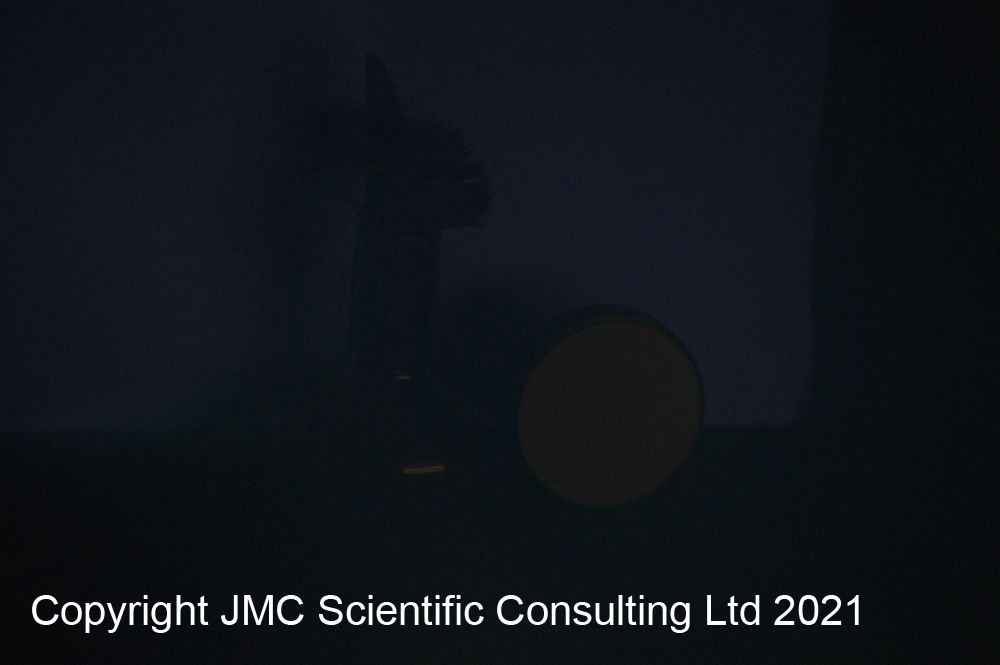
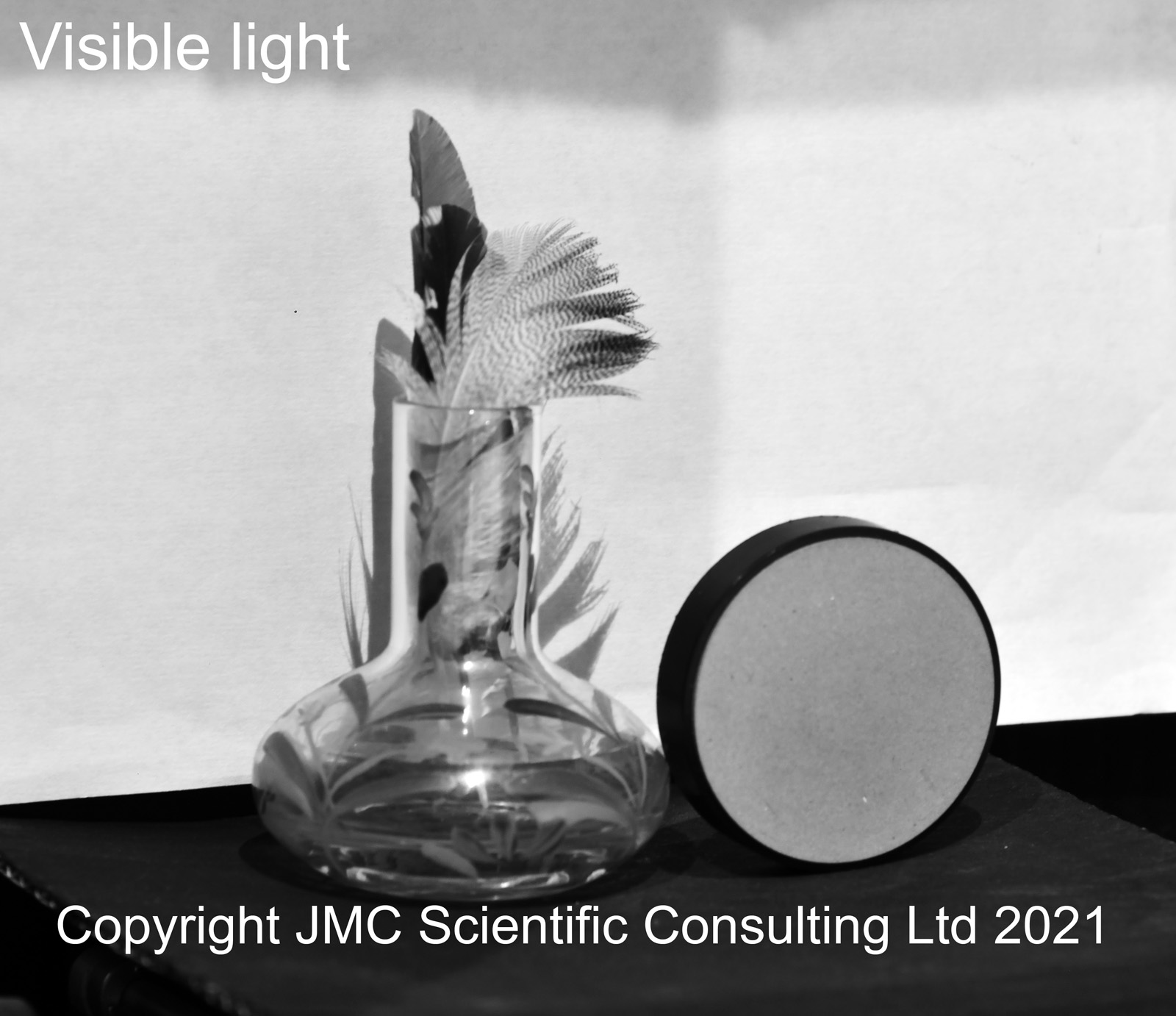
Just for comparison, here it is when imaged in visible light.
Visible image captured with the monochrome Nikon d850
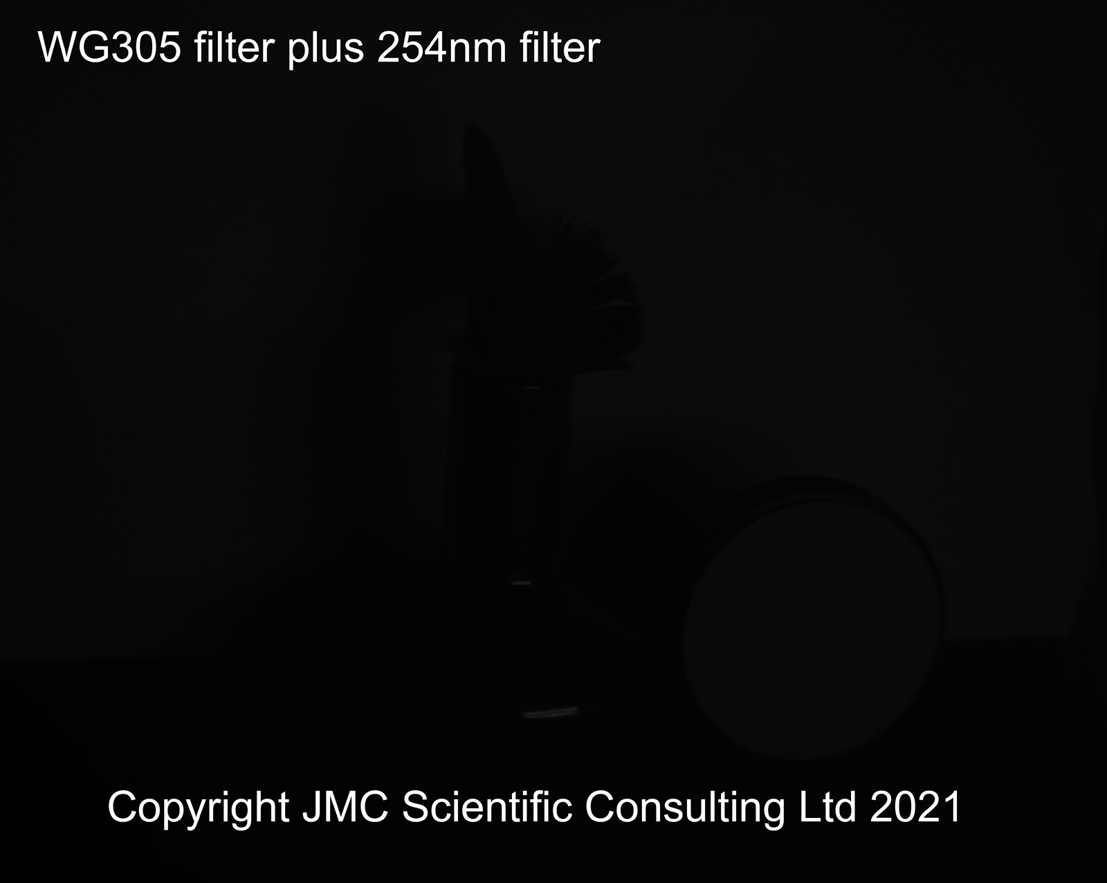
The first thing to note was the vase – the glass looks black in UVC. This is because the glass strongly absorbs the UVC. How did I know this was a UVC image? It’s very easy to fall into the trap of assuming that this is a UVC image, but by using a Schott WG305 long pass filter as well I could block the UVC while letting longer wavelengths through, and this is what I got with that.
WG305 filter image
While it is hard to see online, there is a really faint image here with the Schott WG305 filter in place, so it is fair to say that my 254nm image, while predominantly UVC is not all UVC and there is a tiny amount of contamination of the image by longer wavelengths. However it is fair to say that the image with the 254nm filter alone is mainly a UVC image.
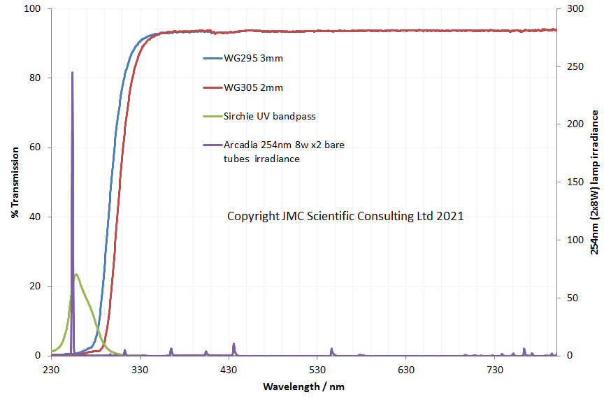
At this point it is worthwhile looking at the properties of the filters and the light source to help explain what is going on. Here they are between 230nm and 800nm.
Filter and light properties between 230nm and 800nm
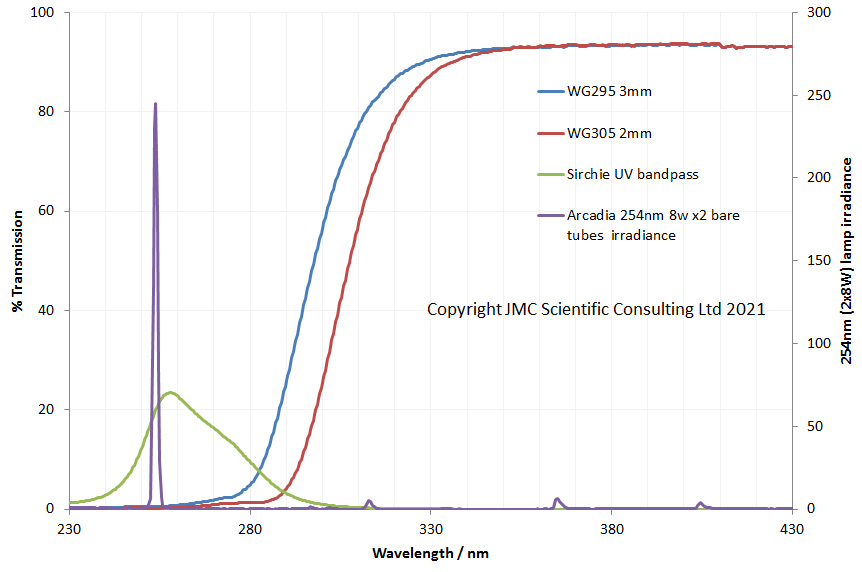
And now between 230nm and 430nm.
Filter and light properties between 230nm and 430nm
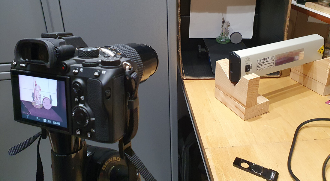
What are these graphs telling us? The light source (the purple line) has a strong emission at 254nm, with a few very small peaks at longer wavelengths. There may well be more lines 800nm but I cannot see up there. The peak transmission of the 254nm band pass filter (the green line) coincides with the 254nm lamp which is good. The red line (WG305 filter) is the filter I used to check for leaks and as you can see there is a little bit of an overlap with the tail of 254nm filter at around 300nm, and this could be source of the faint image in the WG305 photo above. I may try a slightly longer wavelength long pass filter to check that. The blue line is a ‘red herring’, as I haven’t included images with that filter here, but it is another long pass filter and was part of my other tests on the setup. Here’s a snap of the setup I used to capture the images.
The observant amongst you will notice that the camera in the image above is not a Nikon d850. It is actually my Sony A7III which has been converted to multispectral imaging. This camera, unlike the d850, still has it’s Bayer filter though, so can capture colour UV images. More to come on that, as I’ve been able to get colour images down in the UVC region with it…..
When this experiment started, I honestly did not know what to expect. I’d assumed that the camera wouldn’t be sensitive enough to see anything this far down, but I was wrong and the camera is indeed sensitive enough to see 254nm light. Always nice to be surprised and this opens up its possible uses to new areas such as coronal imaging. Filtering will need some more work, as it’d be good to get a more narrow band pass 254nm filter, but for now this one will do the job.
If you’ve made it this far, well done and thanks for reading. If you’d like to know more about this or other aspects of my work, you can reach me here.
When looking out for interesting imaging equipment, I normally have a bit of an idea what I’m after – usually my focus is on UV imaging, and that then has a bearing on the types of things that I am looking for. Since getting into microscopy though my horizons have been broadened as there is some really quirky and interesting stuff out there. This leads me to today post – the Leitz Ks series microscope objectives. These were part of a set of lenses that Leitz produced for a very specific job – looking at the grain in photographic emulsions. Having spent a fair bit of time inhaling fumes in a dark room when I was younger, I thought this was a cool idea and set about trying to find some of these objectives….
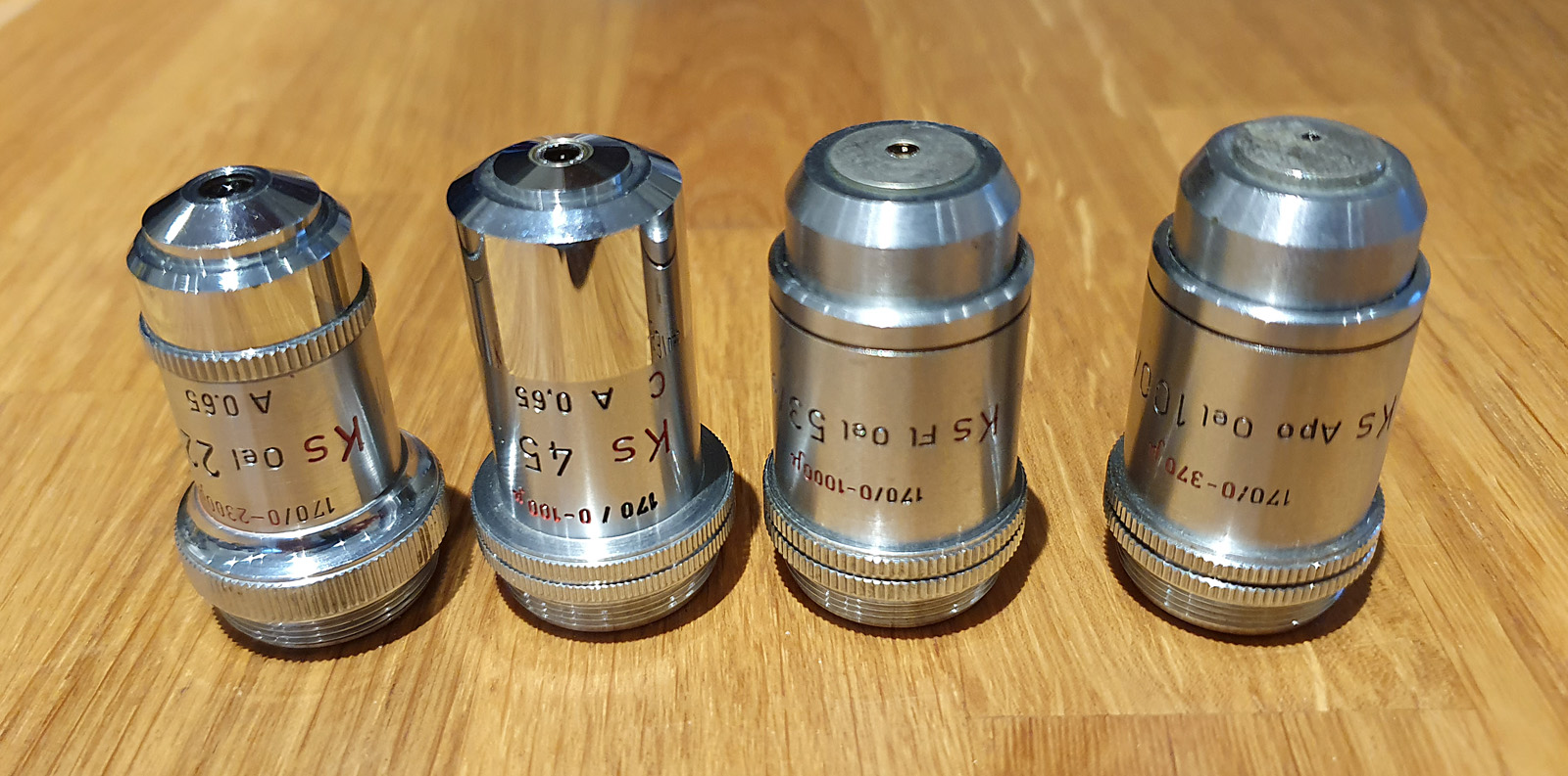
Finding these was not too hard, but finding them for a reasonable price was a bit more difficult. In the end, one came from Germany, one from a dealer in Sweden, and two from a lab equipment reclamation company here in the UK. Here they are.
The 4 Leitz Ks objectives
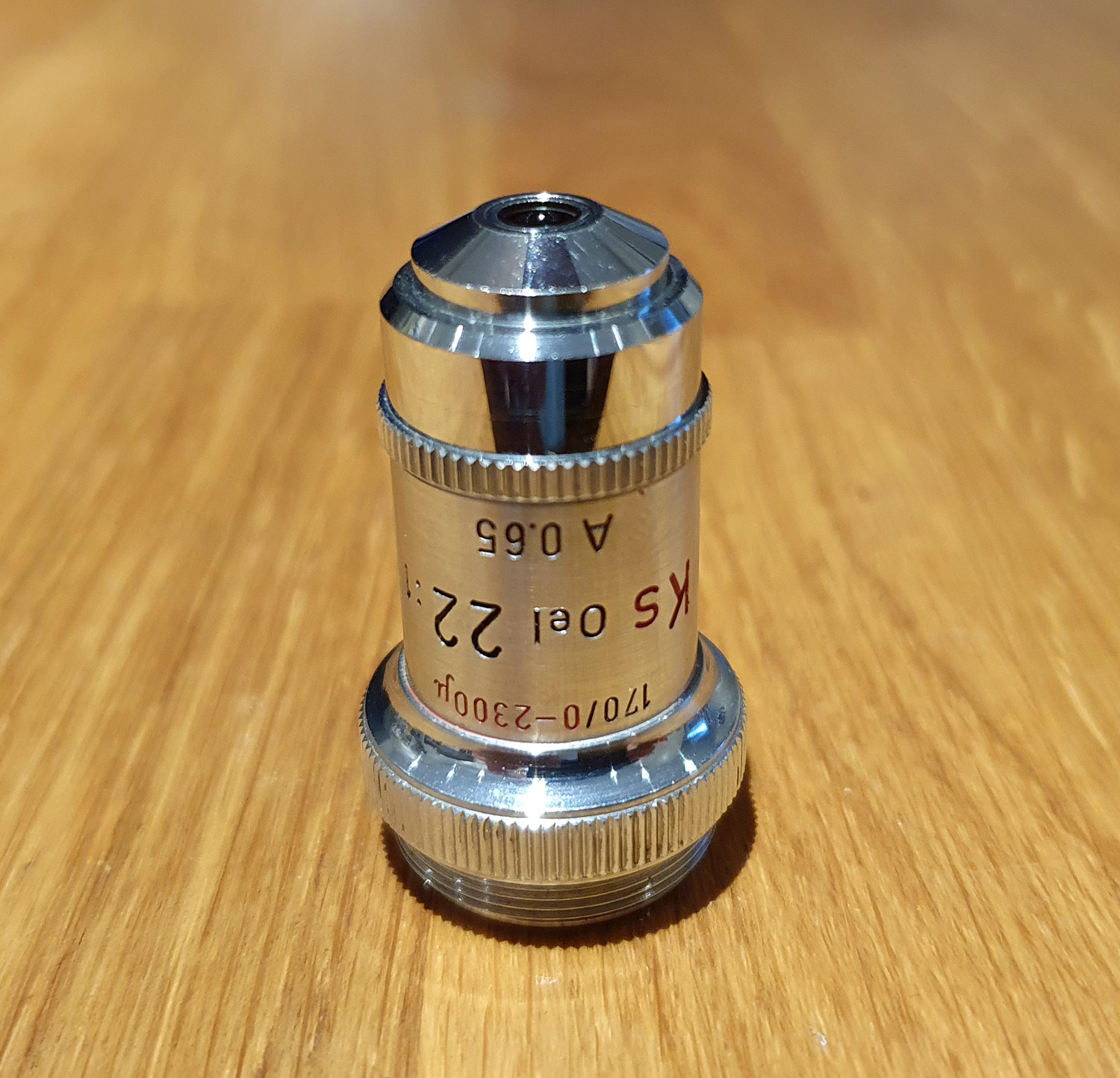
In the range there were 4 objectives. From smallest magnification to largest, there was the 22x Oel (oil immersion) A 0.65.
Leitz Ks 22x objective
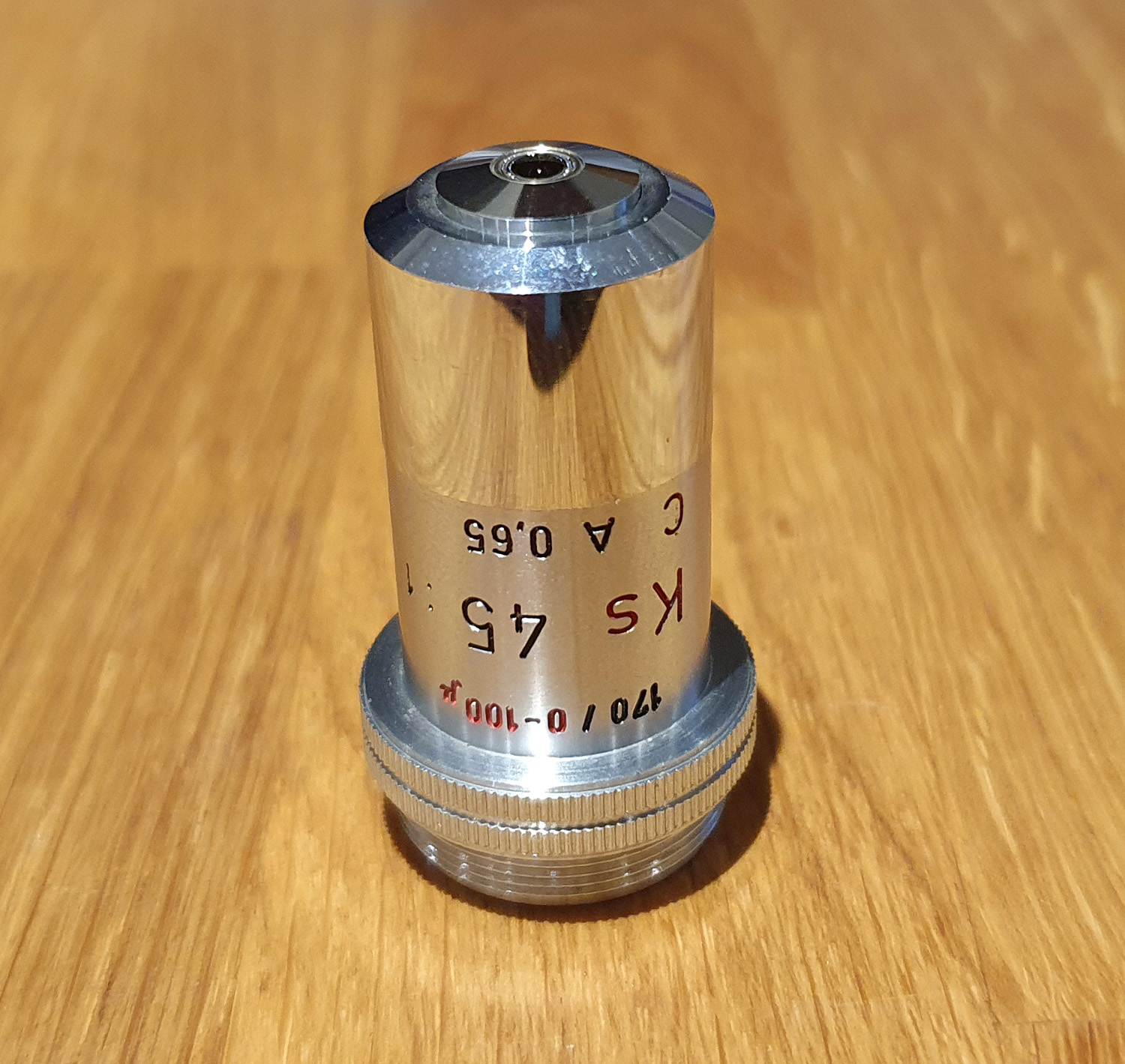
Then we have the Ks 45x A 0.65 dry objective.
Leitz Ks 45x objective
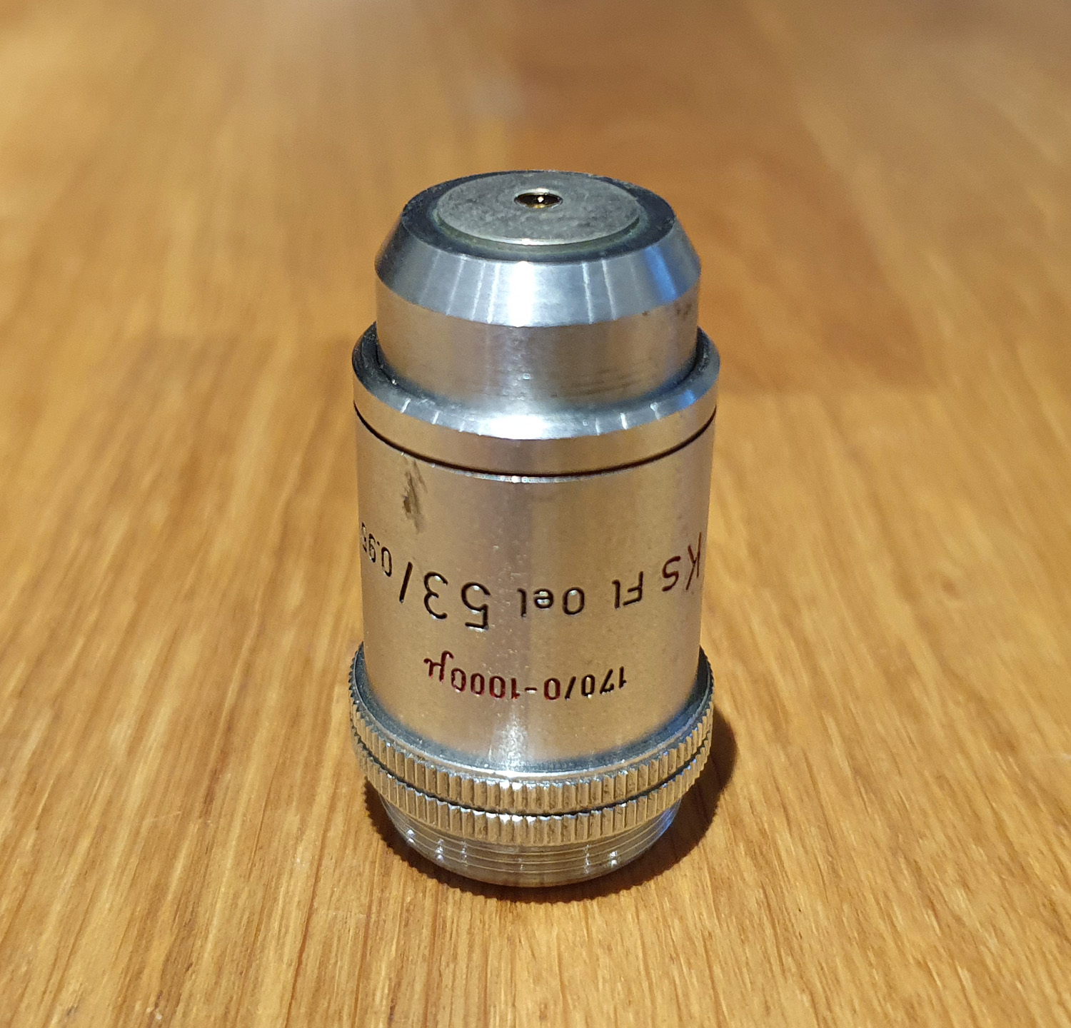
Next is the Ks 53x A 0.95 fluorite oil immersion objective.
Leitz Ks 53x objective
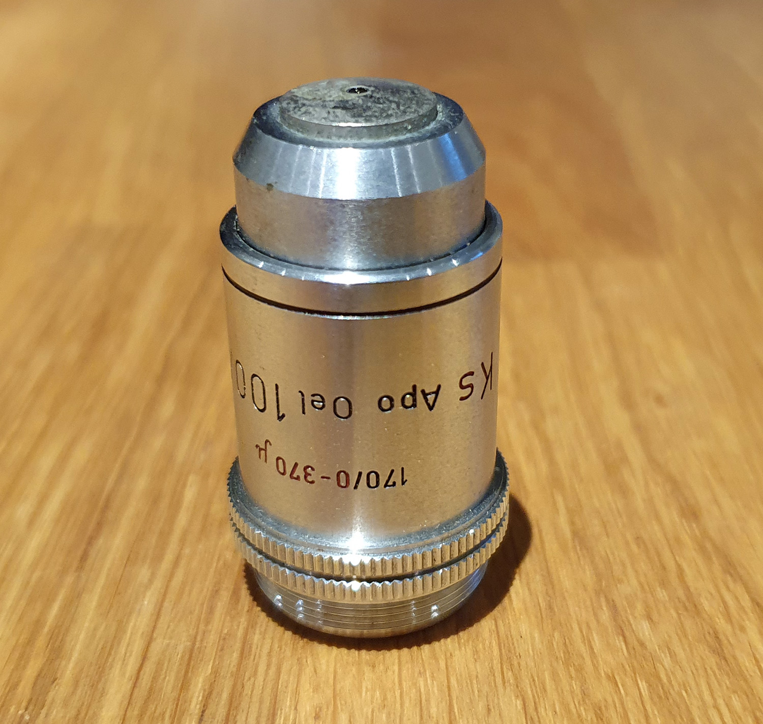
And finally the Ks 100x A 1.32 apochromatic oil immersion objective.
Leitz Ks 100x objective
All of these objectives were designed for Leitz 170mm finite tube length microscopes. Normally, on an objective after the tube length is the thickness of the coverslip that they are designed for, however these are different. With these there are different numbers and then a ‘mu’ symbol.
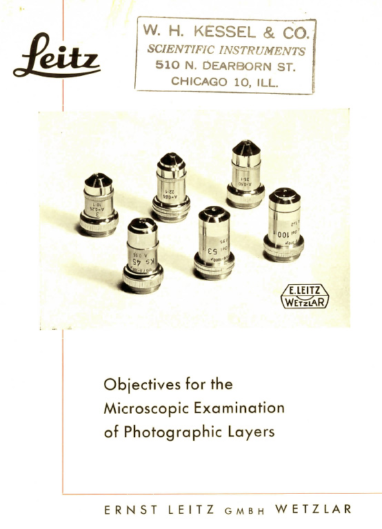
So what’s going on with these objectives? At this point it is a good point to dig back through the archives for some information. There was a Leitz brochure produced for these objectives, and I downloaded a copy from online. Here’s the front page.
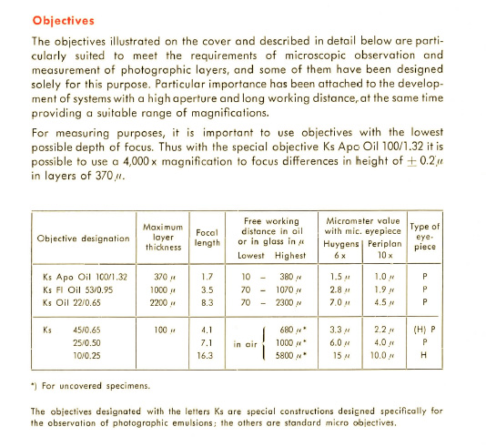
The first page of the brochure give a bit more of a background to the objectives in the range.
As can be seen, the full range had 4 different Ks objectives, and two others. The numbers after the tube length, refer to the maximum layer thickness of the photographic film that they were designed for. Oddly on the 22x objective it says 0-2300, instead of the 2200 it has in the table above, while on the other objectives, the numbers correspond to the ‘max layer thickness’ in the table.
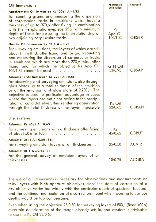
The next page in the brochure gives more details on the objectives.
After getting these I thought I’d see what type of images I could get from them, so dug out an old slide and the immersion oil (for the 3 objectives that needed it). My Olympus microscope has a 160mm tube length (as opposed to the 170mm tube length that these were designed for), but I have used other 170mm tube length objectives with success so thought it was still worth a try. At this point I should be sharing some lovely images showing the grain structure in the slide, however I have nothing for you, sorry. The images were actually not that good, from any of them, and I got sharper ones with my normal objectives. Not sure why this is the case to be honest. I struggle to believe that they are all damaged. Online, I was only able to find one thread talking about using them, and they were struggling too, so perhaps there is something odd about their design which makes setting them up and using them difficult. So for now they remain an interesting piece of history.
Thanks for reading, and if you’d like to know anything about this or other aspects of my work, you can reach me here.