
A couple of weeks ago I posted my first microscope image captured at 254nm using my UV modified Olympus BHB microscope (see here). While it showed the potential of the technique, it highlighted a number of issues which still needed addressing – especially the lighting (making it stronger and more collimated) and the filtration of the light to remove unwanted wavelengths. This is a bit of an update on progress since then, mainly with regards to the lighting, but also a mention of a slight change to filtration of the light which is imaged.
The main issue with the lighting was that it is a light bulb, emitting light in all directions. This is very wasteful and I need a focused, collimated light source, wasting as little as possible. In the original lamp housing there was a glass condenser lens which could be moved in an out to provide some focusing. Glass is fine for visible light, and even maybe for 365nm depending on thickness and coatings, but is no good at all for 254nm as it would just absorb everythin. This means needing to use lenses made from UV fused silica, quartz or materials such as calcium fluoride. As you can imagine the availability of lenses in these materials is much more restrictive (and the cost much higher) when compared with glass. As a result I tend to have to choose off the shelf components, which are ‘close’ to the parameters of the original pieces, rather than ones which are exactly the same. The original glass condenser lens was about 42mm diameter, while off the shelf components were available in 25mm or 50mm diameter. I went with a 25mm UV fused silica aspheric condenser lens with a 20mm focal length from Thorlabs (see here). This was mounted in one of their SM1 tubes, which in turn was screwed in to an SM1 to M42 adapter. The M42 adapter was just the right diameter to fit into the lamp housing where the original lens did, and be held in with the original retaining clip. Bonus. This is where I give a ‘shout out’ to Thorlabs. As I’ve mentioned before, they are great to deal with and have an amazing range of optical equipment. Plus they send out Labsnacks with their orders….. This is how it looked once put together (you can see the lens in the middle of the adapter).
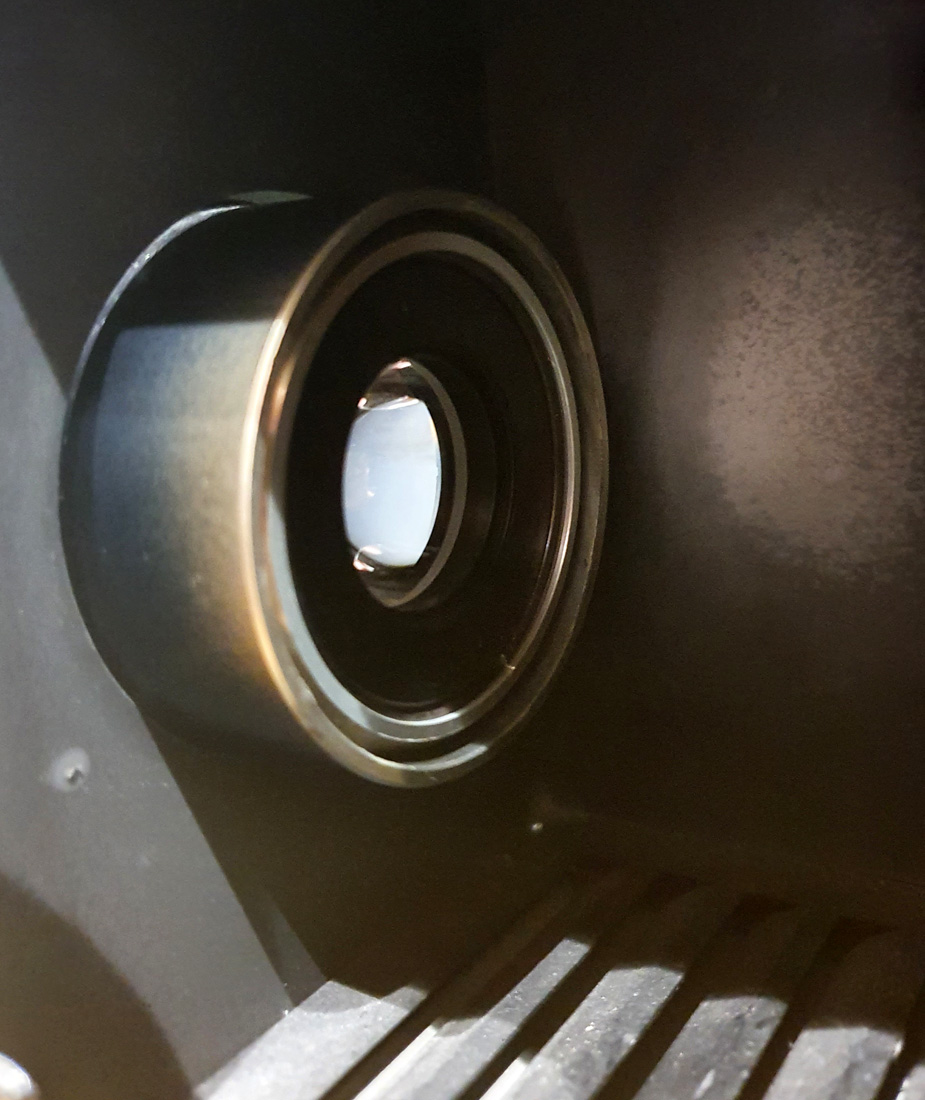
When I measured the intensity of the light at 10cm from the bulb with the lens in place I got about 6x more light than without the lens, which is a great improvement and will help with the imaging.
What do the images look like now? In a moment I’ll some examples from the fused silica/quartz diatom test slide, taken using a 10x Zeiss Ultrafluar NA 0.2 objective lens. The full sized images have been reduced is resolution for sharing here.
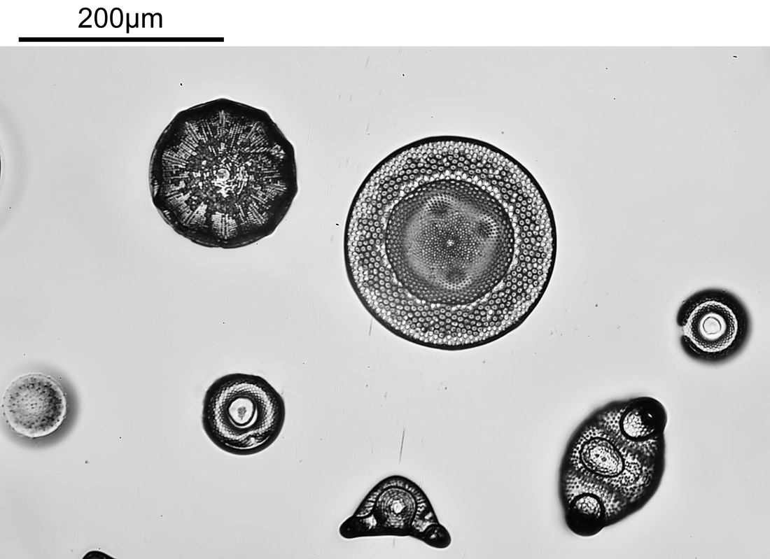
First though, a visible light (white LED) image of part of the slide with the same objective.
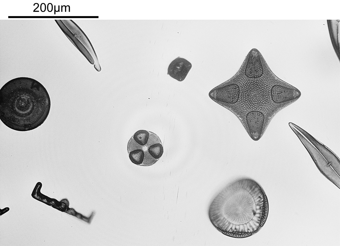
The same region of the slide now imaged at 254nm.

The modified lighting has helped a lot with getting an even light distribution across the image. It’s interesting that some of the diatoms seem to be absorbing quite a lot of light at 254nm while others do not (this is in keeping with some of the literature I’ve read on the subject). I am getting some rings in the lighting, which I think is down to the very reflective surface of the filters. I need to do a bit more work and see if that can be rectified.
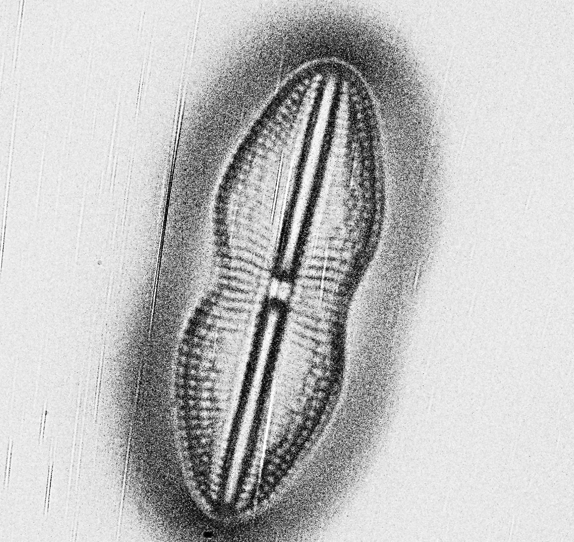
A couple of other images of the slide at 254nm.

Finally, some crops from the image above, shown at the original pixel resolution.
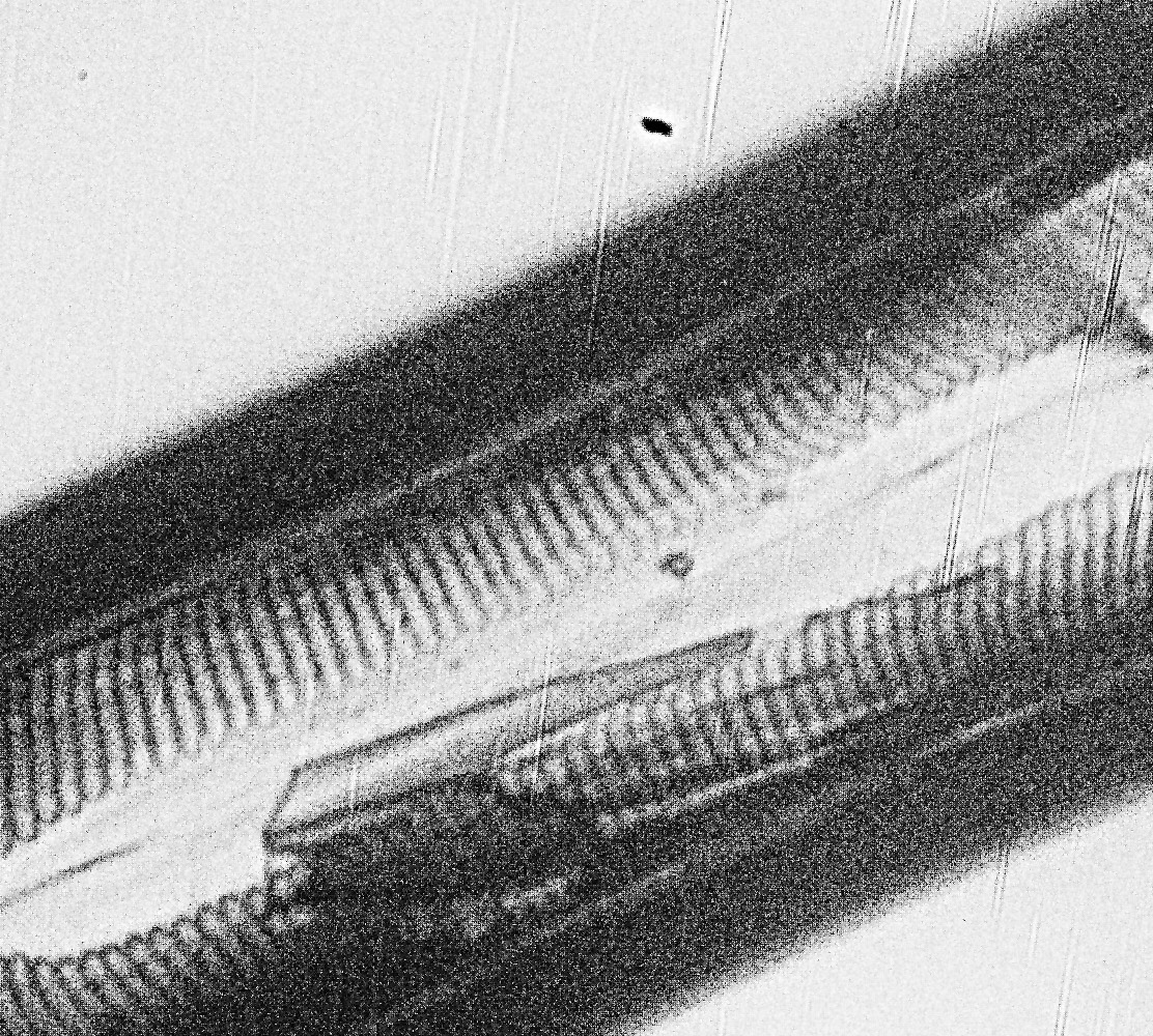
Doing some math on the images, in the original un-cropped images, there were 11 pixels per micron. If you look at basic Abbe resolution calculation for this objective (λ / 2xNA) you’d get a theoretical resolution of 635nm for this objective at 254nm. Some of the features in the cropped images above are of the order of 7 or 8 pixels across or about 750nm, so similar to the theoretical resolution limit predicted by Abbe. Now this is a bit of a simplification, as I really should take into account the NA of the condenser underneath the stage (which would push the theoretical resolution to smaller features) and the MTF function of the camera and lens (which would push it back towards bigger features), but I’ve not had enough coffee for that yet.
The images above are a bit noisy. I had to use 30s exposure at ISO1000 as the camera sensitivity this far into the UV is low. I am hoping longer exposures at lower ISO will help with that in future, or perhaps I’ll try stacking multiple exposures if I figure out how to do that.
Before I wrap up this post, I want to briefly mention filtration of the light before it reaches the camera. In my original post I was using a UVC bandpass filter which came from a forensics camera I bought a few years back. While this had good blocking of longer wavelengths, it had relatively low UVC transmission (about 20%). I decided to get another UVC bandpass filter and stack the two together, the aim being to improve blocking of unwanted wavelengths. The new filter is a Semrock 260/16 Brightline one which I bought from Laser2000 here in the UK (another company I’ve had good experience with in the past). This isolates the 250-270nm region very well, and blocks the rest of the UV and visible light. However it does not block the IR. So far, the initial tests with the two stacked together look good, and I’ll talk more about this filter in a future post as the whole area of filtering light for imaging at 254nm warrants a bit more of a discussion than there is time to do here.
As always, thanks for reading, and if you’d like to know more about this or any other aspect of my work, you can reach me here.
I’ll leave you with my standard warning for anyone considering working with UVC – don’t do it unless you know what you are doing and are using the right safety gear and clothing. UVC can be extremely damaging to eyes and skin, and it isn’t worth taking the risk unless you have the correct safety procedures in place.