
Happy New Year everyone. 2021 brings promise of a new start and I hope to bring you plenty of cool science over the next 12 months. I have some pretty special lenses and microscope kit to review, so watch this space. Today though, we start with an update on the UV microscope build. This has been a project I’ve been working on for about the last 6 months, and has required some major modification of my Olympus BHB to make happen (see here for the previous summary of the work to date). Today an update on the modification of the binocular/trinocular head, and the results of some major mechanical surgery.
When I took the Olympus head (I’ll just refer to it as a ‘head’ from now on, rather than repeating myself every time) apart, I realised that the construction was going to be quite difficult to adapt for UV. There was a lot of thick glass in there, along with a prism which acted as beam splitter – see here for the initial assessment. Instead of trying to replicate the prism exactly, I made the executive decision to cut the prism in half, and replace half of it with a simple block of UV fused silica. This would mean that when the prism was in the position for taking a photo, the light would go straight through to the camera, rather than being split between the camera and the eyepieces. This would result in more light for the camera (a good thing for UV imaging), and with most cameras having some form of live view, I don’t need to look down the eyepiece for the final focus. The window in the bottom part of the head also needed replacing, but this would just need a simple disk of UV fused silica. However both parts needed to be custom made and the prism would need cutting in half to make this all work. To supply the fused silica components and cut the prism down, I went to a company I’ve worked with quite a bit over the last year – UQG Optics – who were able to supply the parts I needed and do the work on the prism. When anything needs to be custom made the costs go up dramatically, and given the tolerances involved were tight, it was a case of ‘measure many times’ before the dimensions went to UQG for cutting.
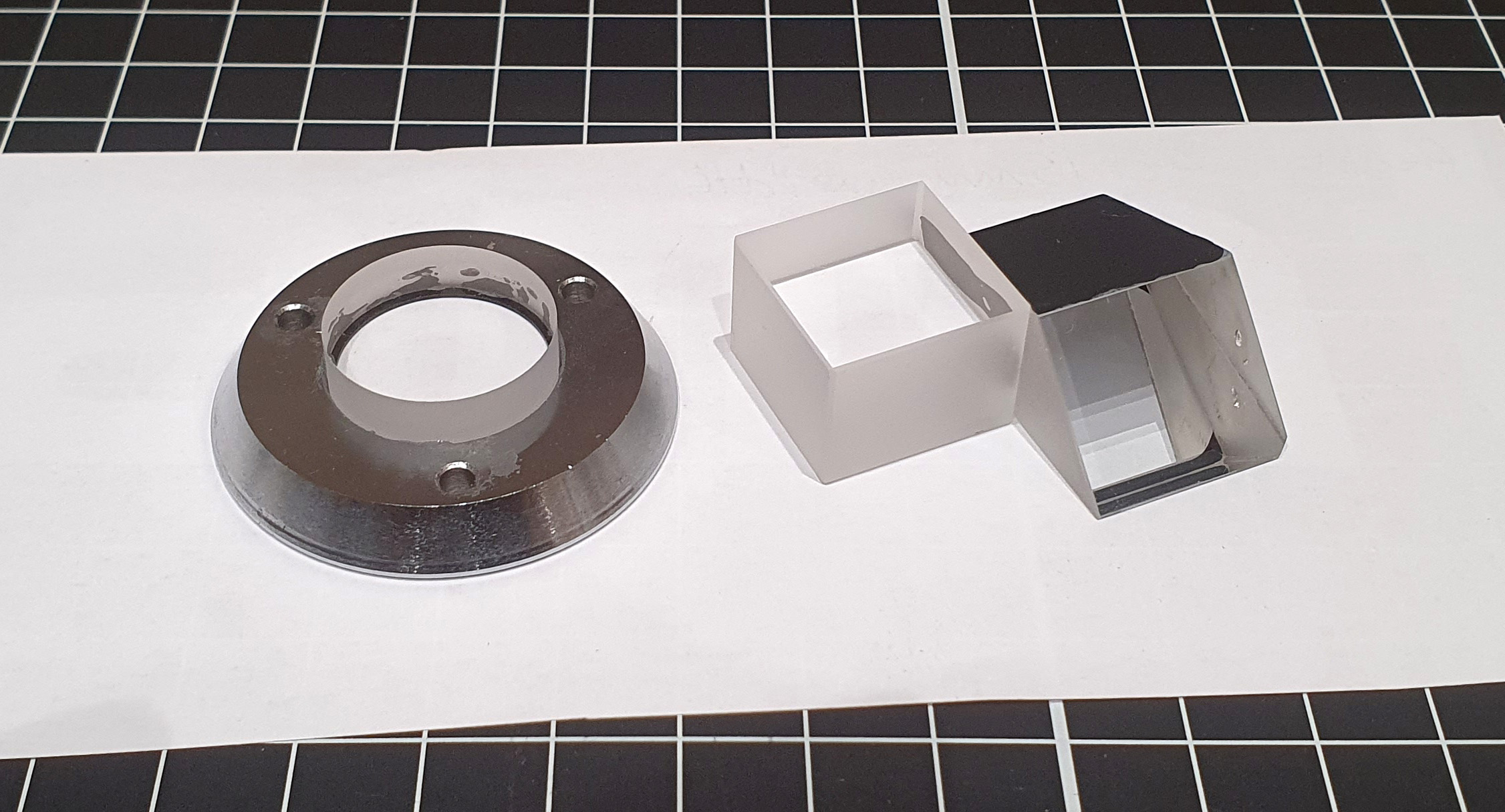
When the two UV fused silica parts arrived, along with the cut down prism beam splitter, I assembled everything and glued the circular window into its metal housing, as you can see below.
Transmission of the new parts, compared with the old ones is given below.

Note the absolute transmission here is probably slightly higher than in real life (by a couple of percentage points). Even after collimation of the light beam for the transmission test, it will still be slightly divergent. Including such thick pieces of glass / fused silica in the path of the beam means that some more light will reach the spectrometer detector than would happen without the glass / fused silica in place. I have tried to minimise this with the setup of the device, but can’t guarantee that it has corrected it fully. The important thing to note is that the new fused silica components have a flat transmission curve as a function of wavelength, unlike the original glass ones, which block varying parts of the UV. The new UV fused silica parts will allow UVB (and even UVC) imaging down to and below 280nm.
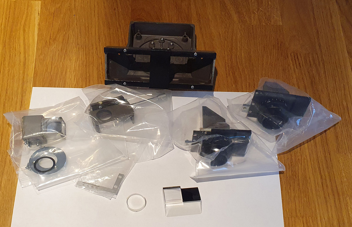
Once the glue had set on these, the head needed re-assembling. Not a simple task, and akin to putting a quart into a pint pot. The picture below give you and idea of the parts that needed to go back into it.
Once back together (after a lot of loosening and tightening screws to get everything aligned, and cleaning of any glass after putting fingerprints on it) it looked like this.
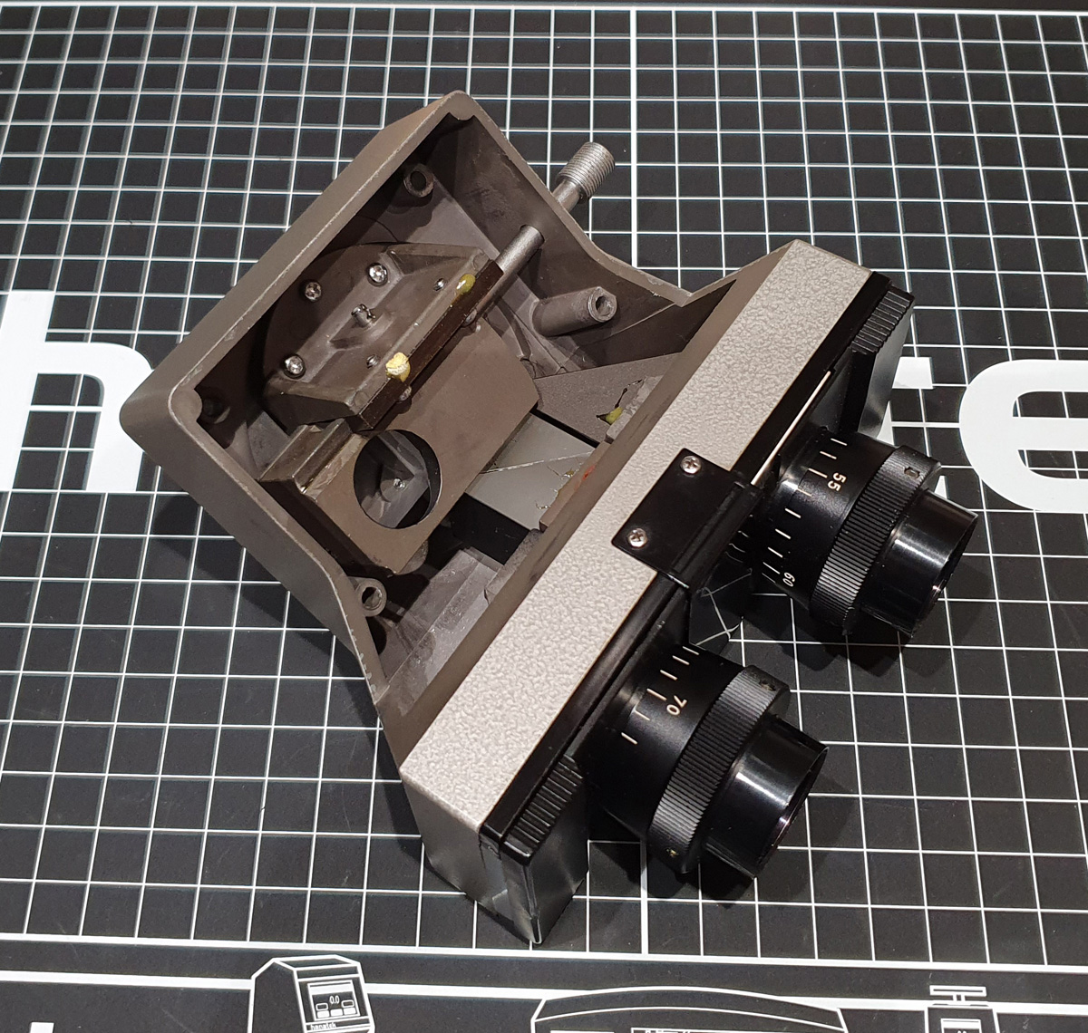
The next step was to put the yellow filters in the base of the tubes for the eyepieces – the idea here being to eliminate any UV that could otherwise reach the eyes. This is part of my ‘belt and braces’ approach to safety when using this device. Not only would any UV have to pass through the glass part of the beam splitter, and the glass eyepieces, but now has to go through yellow filters which have a transmission of <0.01% of anything below 400nm. As mentioned before, I’d still use UV protective glasses when using this, the yellow filters just another layer of protection. Once it is up and running, I’ll be measuring the spectral throughput to the eyepieces to see how low it is. If in any doubt, I’ll just use live view on the camera for all the focusing work. Here’s a view down the tube of one of the eyepieces to the yellow filter.

One thing I haven’t got right was the diameter of the filter needed. The eyepiece tubes are 23.2mm, and I assumed 23mm filters would be fine. However at the bottom of the tube the diameter opens up and the filters rattle around a bit unless the eyepiece tubes are screwed all the way down. This can be rectified by using larger diameter filters, or by gluing the ones I have in place, and I’ll see if I can get access to where I need to to be able to do this. For now the tubes will be screwed fully down, locking the filters in place.
There was a lot of glass in the head, all aligned very precisely, and I had real concerns that this would simply not work well enough, leaving me with a very big bill for a new paperweight. Once assembled, for a quick test I did a visible light image of one of the Diatom Lab strewn diatom slides using an Olympus 20x SPLan objective, and the normal tungsten light source on the microscope. Stacked in Zerene Stacker, here is how it looks (I used a Schott S-8612 filter as this was taken with my multispectral camera and I wanted to remove IR from the image).
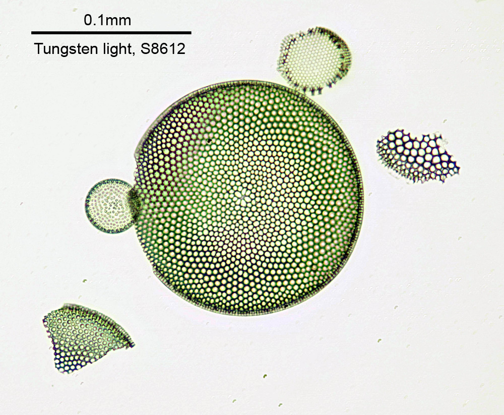
The image above has been reduced in resolution for sharing on the web, and is a crop from the full area imaged, but demonstrates that this modified head can at least give a usable image in visible light. Note, the fuzzy areas in the largest diatom are more down to my stacking technique than anything else.
In theory this is the final part of the UV microscope build – all the glass parts have now been converted to fused silica, and the next stage is to try imaging in the UV. To start with I’ll use 365nm as this is simpler and safer, and I have a couple of light sources (LED and mercury xenon lamp) to try out. I also have a Diatom 2.0 test slide on order from Diatom Lab, so I can look to see how the resolution of the imaging changes when I go from visible to UV. See, I told you 2021 would be exciting.
The original plan was to use this for sunscreen formulation imaging – to be able to image UVA and UVB absorbing components separately to see where they are in the formula – and I’ll certainly be using it for that first. After that we shall see, as there are plenty of other applications for UV imaging, in biology, forensics and other fields.
Thanks for reading, and if you’d like to know more about this or any other aspect of my work, I can be reached here.