UV photography presents some unique challenges above and beyond normal visible light imaging. Not only are cameras not that sensitive, but how good good are the lenses at transmitting the light. Needing to understand this resulted in one of those seemingly simple questions – how do I measure the transmission of camera lenses in the UV? Surely this is a simple enough one to crack. I mean, how hard can it be? As with many of these simple questions, getting the answer isn’t always straight forward. But in the end a solution did come, and I designed and built my own system for measuring lens transmission, vitally important for understanding what you cameras are actually seeing during UV photography. Example transmission plots for some of my dedicated UV lenses are given below.
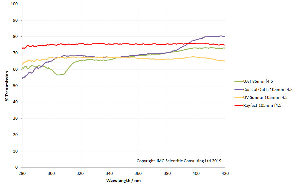
What are we looking at here? These are plots of the amount of transmission between 280nm and 420nm through 4 different lenses designed for UV imaging. This is absolute transmission, and not dependent on the internal aperture of the lens. In essence, how good is a given lens is at transmitting light of specific wavelengths. Why do you need to know this? Well, if you design an imaging system for use in the UV, and the camera is sensitive down to 300nm, if the lens doesn’t transmit down there, then you are never going to be able to image down there. The lenses above aren’t an issue for that, as they still have good transmission at 300nm, however these are dedicated UV lenses. What about more normal camera lenses, how do they behave? Below are the transmission plots from a selection of new and old camera lenses and an enlarger lens.
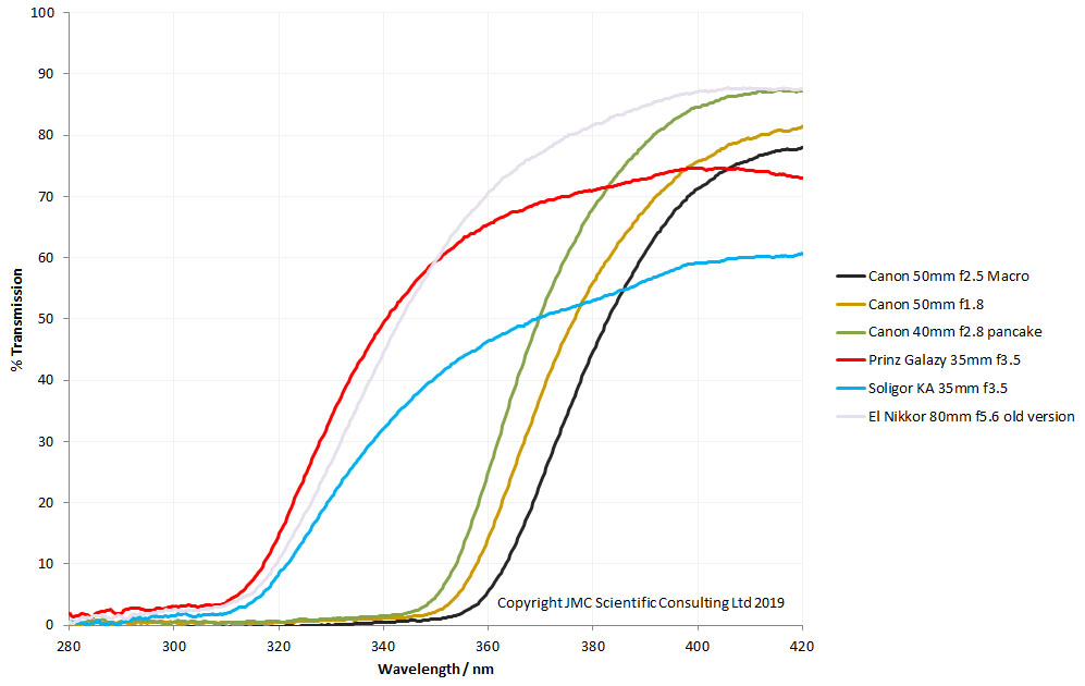
These lenses behave very differently to the UV lenses above. As the wavelength drops, their transmission reaches a certain point and then drops quickly. Why is this? The UV lenses in the first graph are made of some very special materials – silica and calcium fluoride – rather than glass and plastic. Silica and calcium fluoride do not block the UV like glass and plastic lens elements. Also, the UV lenses tend not to have glued lens elements, as the glues can also absorb lots of UV. As a final advantage the UV lenses tend not to have anti-reflective coatings, or if they do they are optimised for UV.
Older camera lenses such as the Prinz Galaxy 35mm and Soligor 35mm ones above can be good options for UV imaging. Although the absolute amount of light they transmit is typically lower than more modern lenses, they tend to let shorter wavelength light through. However they are not all the same. Very often lens retailers bought lenses from different manufacturers, and put their own brand on them before selling them. So for instance, not all Prinz Galaxy 35mm lenses behave like this one. You still need to check you lens before knowing how it will behave.
The EOS Canon lenses tested – the 40mm f2.8 pancake, 50mm f1.8 and 50mm f2.5 macro – were all different. The 50mm f2.5 macro was the worst lens tested here, and is one of the worst prime lenses I have tested for UV transmission. It is best avoided for UV imaging if you want to get the best images. The 40mm f2.8 pancake lens is the best Canon EOS lens here in terms of transmitting UV, and is not a bad lens for UV photography, especially as it retains autofocus.
The El-Nikkor 80mm f5.6 enlarger lens is very good for UV – good transmission to short wavelength. This does however need a helicoid to allow focusing on a camera, as being an enlarger lens they didn’t come with one originally. This was the old chrome ring version of the lens, the newer all plastic version doesn’t transmit as well in the UV.
How did I produce these curves? I originally tried a very simple approach – light source, fiber, collimating lens to produce a parallel beam of light. Shine that into the front of the test lens. At the rear of the test lens, have another collimator, then a fiber, then the spectrometer. Surely that will be fine. Unfortunately not. The issue being that collimating lenses are not perfect and the lens being tested further focuses the light into the collection fiber. The result being that you can get % transmission values above 100% which is obviously wrong. From my research, the way round this is to use an integrating sphere to collect all the light from the rear of the lens before it is analysed. The problem with this though, is that you need a lot of incoming light, to get round the losses within the integrating sphere. My little fiber optic light source wasn’t up to the job. So I used a second hand 200W Hamamatsu LC8 source with a Xenon lamp normally used in the electronics industry. The light from this was focused using a Bausch and Lomb UV capable condensor lens into a light proof box. A movable baffle with adjustable iris allows me to control the diameter of the beam of light that goes through the test lens. Light then goes through the test lens into an integrating sphere (bought second hand from eBay) where it is collected by an Ocean Optics FX spectrometer. As with most of my home built projects, the whole thing was assembled using things I had in the workshop, painted black on the inside, and it looks like this.
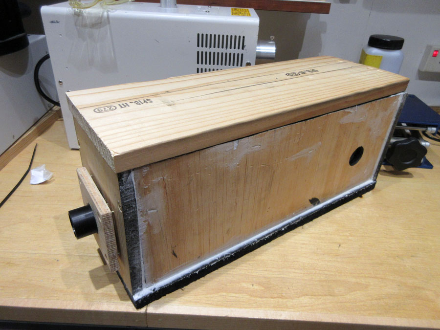
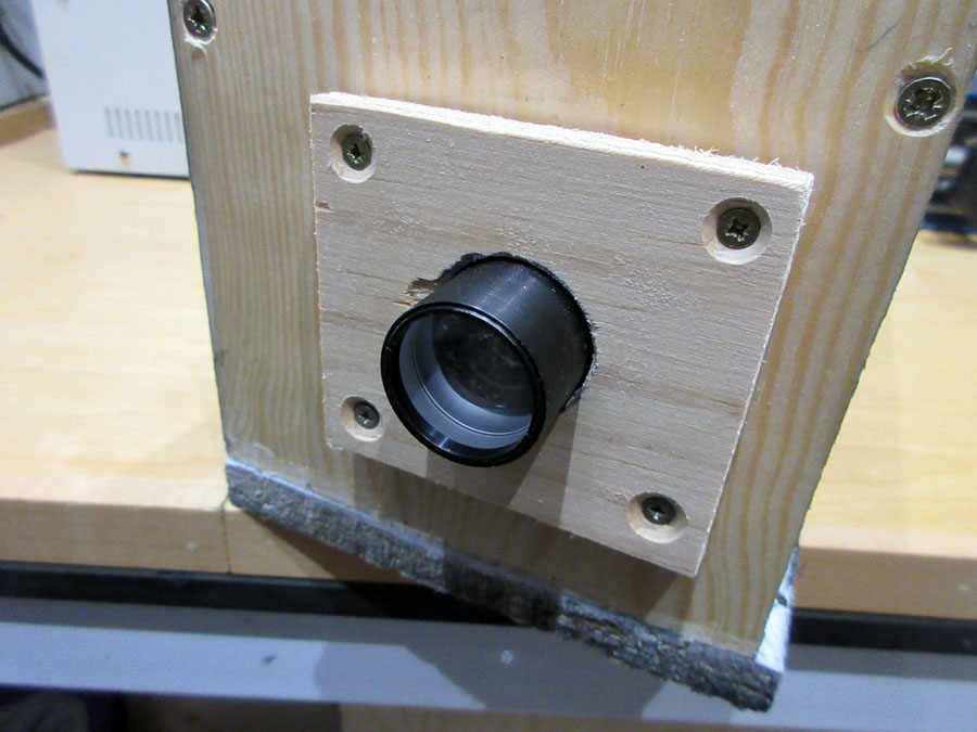
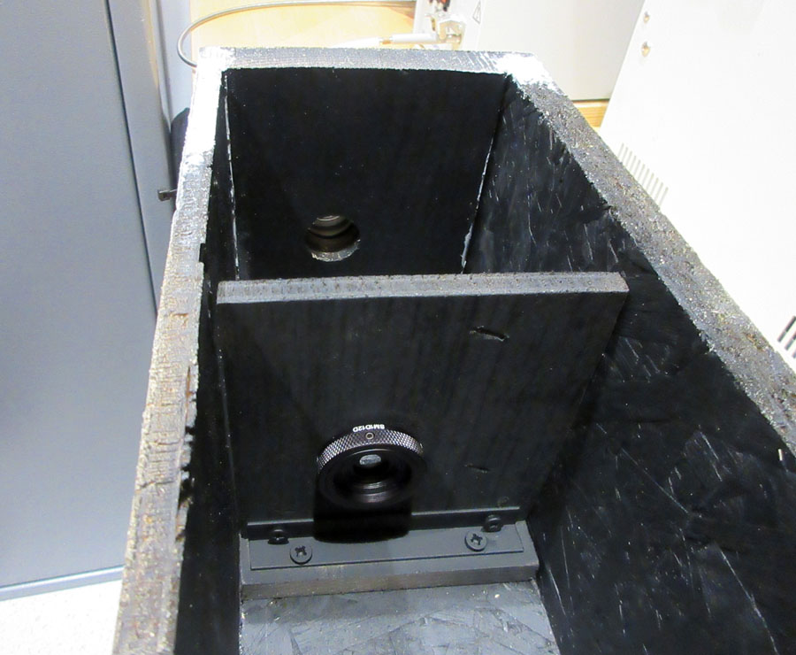
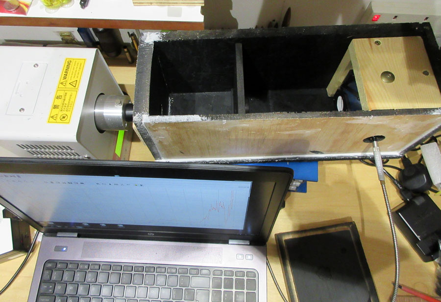
During measurement the lid is placed on the box and this excludes any external light. After that its a simple transmission measurement. Calibrate for dark, and for 0% and 100% transmission, place the test lens in and take the measurement. Given the nature of the light source and spectrometer I have, I can do measurements between 280nm and 420nm with this lamp. Outside of this it gets a bit noisy. This isn’t a huge problem, in the visible region there are a few people that can do lens transmission measurements, and below 280nm most cameras aren’t sensitive anyway.
I can now offer lens transmission measurements in this 280nm to 420nm region. If you think this would be useful for your research, please contact me for details, here.
